1
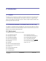
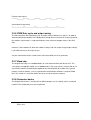
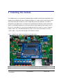
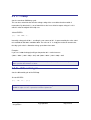
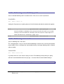
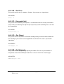
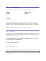
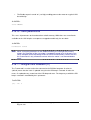
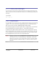
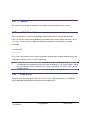
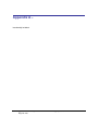
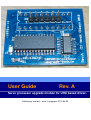
User Guide
Rev. A
Servo processor upgrade module for UHU based drives.
Preliminary manual – work in progress 2010-06-06
Table of Contents
1
2
3
ABOUT THIS GUIDE .................................................................................................................4
1.1
WHO SHOULD USE IT ............................................................................................................4
1.2
TYPOGRAPHICAL CONVENTIONS .............................................................................................4
INTRODUCTION .......................................................................................................................5
2.1
PURPOSE .............................................................................................................................5
2.2
DIFFERENCES BETWEEN THE MODULE AND THE UHU CHIP ........................................................5
INSTALLING THE MODULE ......................................................................................................9
3.1
4
SETTING UP THE TERMINAL SOFTWARE ..................................................................................10
COMMAND REFERENCE .......................................................................................................12
4.1
A – ACCELERATION FEED FORWARD......................................................................................12
4.2
C – CLAMP .........................................................................................................................13
4.3
D – DIFFERENTIAL GAIN .......................................................................................................13
4.4
E – FOLLOWING ERROR LIMIT TRIP POINT ...............................................................................14
4.5
F – FOLLOWING ERROR SCALE .............................................................................................14
4.6
G – GET PARAMETER ..........................................................................................................15
4.7
I – INTEGRAL GAIN ...............................................................................................................19
4.8
J – ANTIDITHER REGION .......................................................................................................19
4.9
K – ANTIDITHER SCALE ........................................................................................................19
4.10
L – SERVO LOOP RATE ........................................................................................................20
4.11
O – OFFSET .......................................................................................................................20
4.12
P – PROPORTIONAL GAIN .....................................................................................................21
4.13
Q – QUIT SERVO .................................................................................................................21
4.14
R – RESET / RESTART .........................................................................................................21
4.15
S – SAVE PARAMETERS .......................................................................................................22
4.16
T – INTEGRAL TIME CONSTANT (TI)........................................................................................22
4.17
V – VELOCITY FEED FORWARD GAIN ......................................................................................23
4.18
X – STEP MULTIPLIER ..........................................................................................................23
4.19
Y – ENCODER FILTER ..........................................................................................................24
4.20
Z – DATA RECORDER MODE .................................................................................................25
4.21
? – MENU...........................................................................................................................27
4.22
+/- - RELATIVE MOVE ...........................................................................................................27
Servo upgrade module - userguide.doc
Page 2 of 30
Copyright 2010
4.23
- PEAK ERROR ....................................................................................................................27
APPENDIX A –................................................................................................................................28
APPENDIX B – FOLLOWING ERROR SCALE ................................................................................29
DOCUMENT REVISION HISTORY. ................................................................................................30
Servo upgrade module userguide.doc
Copyright 2010
Page 3 of 30
1 About this guide
This document is divided into the following chapters:
•
Chapter 1, About this document
•
Chapter 2, Introduction.
•
Chapter 3, Installing the module and verify that it is working.
•
Chapter 4, “Command reference”, describes the modules commands.
•
Appendix A
•
Appendix B, The following error scale feature explained.
•
Appendix C
1.1 Who Should Use It
This guide is intended for users of the servo module. The user is expected to have a general
understanding of how a closed loop servo system operates as well as general electronics and
PC knowlege.
1.2 Typographical Conventions
This document uses the following typographical conventions:
•
Angle brackets are used to illustrate a button press such as <ENTER>
•
Commands, as entered by the user, appears in italic, like: D1234<ENTER>
•
Response from the module, as shown in the terminal software window appears in
monospace font, like: (D) – Kd: 1234
Servo upgrade module - userguide.doc
Page 4 of 30
Copyright 2010
2 Introduction
2.1 Purpose
The purpose of the servo processor module is to be drop in replacement for the popular UHU
servo controller chip. Simply replacing the UHU chip with servo processor upgrade module
allows current hardware to attain higher step-rates and/or use higher encoder resolutions than
previously possible with the UHU chip.
2.2 Differences between the module and the UHU chip
The module was designed to be pin-compatible with v3.0 of the UHU chip. With that said there
are differences between the two and the following section of this document will try to cover the
differences that need to be known before hand.
2.2.1 Module pinout
The following shows the actual pinout of the module:
Pin 1: Reset/MCLR (active low)
Pin 14: Fault input (active low)
Pin 2: RXD (data to module)
Pin 15: PWM output (locked antiphase)
Pin 3: TXD (data from module)
Pin 16: Enable output (active high)
Pin 4: Not used, not connected
Pin 17: Fault output (active low)
Pin 5: Not used, not connected
Pin 18: Firmware status LED (see 2.2.1)
Pin 6: Step input
Pin 19: Not used, not connected
Pin 7: Dir input
Pin 20: +5V / Vcc
Pin 8: Not used, connected to high Z pin.
Pin 9: Not used, connected to high Z pin.
Pin 10: GND / Vss
Pin 11: Not used, not connected
Pin 12: Encoder input A
Pin 13: Encoder input B
Servo upgrade module userguide.doc
Copyright 2010
Page 5 of 30
2.2.2 Pins 4 & 5
On the UHU chip pins 4 and 5 are used for the crystal oscillator. The module features its own on
board oscillator so these pins are not used nor connected to anything on the module. You can
safely leave the 24MHz crystal for the UHU chip on the servo drive PCB.
2.2.3 Pins 8 & 9
On the module pins 8 and 9 are connected to pins on the modules CPU which, as of this writing,
are not being used and are set to high impedance mode (inputs). In future firmware versions
these pins may be used for other function which would then require rework of the servo drive
PCB.
Several incarnations of the UHU based drives have pin 8 and pin 9 in parallell with pins 12 and
13 of the chip (the encoder inputs). This seems to come from earlier versions of the original chip
while the documentation for v3.0 states that the encoder inputs are on pin 12 and 13 which is
where they are on the module.
As long as your PCB is layed out to have the encoder signals on, at least, pins 12 and 13 it is OK
to leave everything as it is. If the encoder signals are available on pins 8 and 9 as well that won’t
be a problem with this version of the module.
2.2.4 Pins 11 & 18
These pins are not used nor connected to anything on the module.
2.2.5 Firmware status LED
The operation of the firmware status output differs from that on the original UHU chip. On the
original UHU chip this output was simply held at a constant low level (LED ON) when the chip
was operating correctly. On the module it blinks in certain patterns corresponding to the current
state of the module. Following error and external fault are two states that can easily be
recognised by simply looking at the firmware status LED.
Normal state:
rHhhhhhhhhhhhhhhhhhhhhhhflllllllllllllllllllllllrhhhhhhhhhh
Following error:
rhHfllrhhfllrhhfllrhhfllrhhfllrhhfllrhhfllrhhfllrhhfllrhhfll
Servo upgrade module userguide.doc
Copyright 2010
Page 7 of 30
External fault request:
Hhhhhhflllllrhhhhhflllllrhhhhhflllllrhhhhhflllllrhhhhhfll
Servo abort (Q-command)
hfllllllllllrhflllllllllrhflllllllllrhflllllllllrhfllllll
2.2.6 PWM Duty cycle and output swing
The UHU chip limits the output duty cycle, or output swing, to between 13 and 87% in order to
allow the bootstrap capacitors in the bridge drive enough time to refresh their charge. By default
the modules C-parameter is setup to provide the same amount of outpput swing as the UHUchip.
However, if the hardware on which the module is being used can accept a larger output swing it
is possible to increase the it up to 8-92%.
See the command reference section of this manual for details on the C-parameter.
2.2.7 Baud rate
The original UHU chip uses 34800baud 8N1 for serial communication with the host PC. The
servo processor upgrade module uses 57600baud 8N1. This means that it’s not possible to use
any terminal software specifically developed for the UHU chip with this module. Any “general
purpose” terminal software, such as Hyperterminal and Realterm will work if setup for 57600
8N1. See section 3.1 for further details on how to set up the terminal software.
2.2.8 Parameter banks
The original UHU features several banks to which complete sets of settings can be saved and
recalled. This module only have one single bank.
.
Servo upgrade module - userguide.doc
Page 8 of 30
Copyright 2010
3 Installing the module
The module consists of a printed circuit board with pin-headers matching the 20-pin dual-in-line
footprint of the original UHU chip. Installing the module is a simple matter of removing the UHU
chip and mounting the module in its place. Depending on how your particular servo drive is
designed it is possible that the servo processor module doesn’t fit directly in place of the UHU
chip as surrounding components may interfere with the larger footprint of the module. If this is
the case it’s advisable to use one or more 20-pin dual-in-line IC sockets as ‘raisers’ to get the
module “above” the surrounding components. Make sure to secure the module in case the
‘stack’ is high – using some hot melt glue, RTV silicone or similar.
Here’s a photo of the module mounted on the HP-UHU drive:
Note: It’s highly recommended to use high quality IC sockets with machined pins.
Servo upgrade module userguide.doc
Copyright 2010
Page 9 of 30
3.1 Setting up the terminal software
Here we will go thru how to set up Hyperterminal which comes with most versions of Windows to
communicate with the module. However, any terminal emulating software capable of talking to a
serial port should work.
To set up Hyperterminal, start a new connection, give it a name and click OK. Select the
appropriate COM port to which you connect your drive and click OK.
Servo upgrade module - userguide.doc
Page 10 of 30
Copyright 2010
Select 57600 baud, 8 databits, 1 stopbit and no flow control. Finally go to File menu and select
Properties, click the ASCII Setup button and tick the checkbox for echoing typed characters
locally.
Power up the drive and you should see a message on screen, now type ?<ENTER> and the
module should respond with the setup menu:
(Actual content of menu may differ)
Servo upgrade module userguide.doc
Copyright 2010
Page 11 of 30
4 Command reference
This section explains the various settings and commands that are available. To change a setting
simply type the letter corresponding to the setting you want to change followed by the value to
which you want to change it and press <ENTER>. The module will then respond with a
confirmation. For example, to set the proportional gain you enter P1234<ENTER> and the
module responds with: (P) – Kp: 1234
When all settings are to your liking the ‘S’ command is used to save them to the on board
EEPROM memory. Simply send S<ENTER> and the module will respond with Parameters
saved to EEPROM
All settings accepts integer values only, some uses signed numbers, ie. they can be set to
negative values by preceeding them with a “-“. It is described in this manual when and where
negative values are applicable.
No floating or fixed point numerical values are allowed (simply – no decimal points).
4.1 A – Acceleration feed forward
Sets the acceleration feed forward gain.
The acceleration feed forward works like the derivative term of the PID filter but instead of
working with the difference of the error between PID updates the acceleration feed forward
works on the difference of the commanded velocity (ie. the acceleration) giving the output some
extra “push” when accelerating and some extra “pull” when deccelerating.
A100<ENTER>
(A) – A.ff: 100
Servo upgrade module - userguide.doc
Page 12 of 30
Copyright 2010
4.2 C – Clamp
Sets the maximum PWM duty cycle.
This can be used to limit the effective voltage swing of the servo drive that the module is
mounted to. By default this is set to 760 which results in an effective output swing of 13-87%
which is what the original UHU chip uses.
C500<ENTER>
(C) – Max PWM: 500
Internally a dutycycle of 50% - resulting in a net current of 0A - is represented by the value 1024.
0% would be 0 and 100% would be 2048. The value of ‘C’ is simply the maximum amount that
the duty cycle value is allowed to swing, up or down from 1024.
Example:
If you set C=400 the dutycyle will get clamped to 30.5 - 69.5% because
(100% / 2048 * (1024 - 400) = 30.5) and (100% / 2048 * (1024 + 400) = 69.5
The maximum output swing of the module is 8-92% (C=860). Setting ‘C’ to a value higher than
860 is possible but will have no effect.
4.3 D – Differential gain
Sets the differential gain of the PID-loop.
D1100<ENTER>
(D) – Kd: 1100 (900)
The value shown within paranthesis is the gain that will be applied when the error is within the
antidither region. See the J-parameter and the K-parameter.
Servo upgrade module userguide.doc
Copyright 2010
Page 13 of 30
4.4 E – Following error limit trip point
Sets the allowed following error in encoder counts. Please also see the F-parameter.
E75<ENTER>
(E) – Error limit: 75
Setting the E-parameter to anything above 32767 will effectively disable the trip limit all together.
Warning:
Setting the E-parameter to very large values, or disabling it completely, can result in the
internal calculations overflowing causing unexpected results like motor reversal and/or
runaway etc. Be careful with this. Generally a value of E equal to a couple degrees of
motor shaft movement is considered a “proper” value.
4.5 F – Following error scale
Sets the following error scale value.
This setting provides a way to scale the allowed following in relative to the currently commanded
motor velocity. That is, the higher the commanded velocity is the larger following error is allowed
without faulting.
F256<ENTER>
(F) – Error scale: 256
If you don’t want to use this feature simply set it to 0. The following error trip limit you specify
with the E command will then be what you get – no matter what the commanded velocity is.
For more details about this setting please see Apendix B.
Servo upgrade module - userguide.doc
Page 14 of 30
Copyright 2010
4.6 G – Get parameter
The G command is used in conjunction with a second letter to get various internal, non
changeable parameters and variables that can be useful during set-up and tuning:
4.6.1 GV – Get Velocity
This gets the current motor velocity in encoder counts per servo loop cycle. It’s presented as a
signed value.
GV<ENTER>
Velocity: -63
4.6.2 GP – Get Position
This gets the current motor position. Currently it’s being presented as two 16bit numbers
corresponding to the the high and low word of the internal 32bit position register.
GP<ENTER>
Pos: 3, 46259
In the above example the actual motor position is 3*65536 + 46259 = 242867 encoder counts.
The 32bit position register is signed 2’s compliment meaning that if the most significant bit is set
the number is negative.
4.6.3 GT – Get Target (setpoint)
This gets the current target position or setpoint.
GT<ENTER>
Setpoint: 3, 46259
As with the GP-command the setpoint is preseneted as two 16-bit numbers representing the
high and low word of the internal 32bit setpoint register.
Servo upgrade module userguide.doc
Copyright 2010
Page 15 of 30
4.6.4 GE – Get Error
This gets the current error (ie. Setpoint – Position). It’s presented as a signed value.
GE<ENTER>
Error: -8
4.6.5 GF – Get scaled limit
This gets the actual following error trip limit as calculated based on the currently commanded
motor velocity, the following error trip limit (the E-parameter) and the following error scale value
(the F-parameter).
GF<ENTER>
Scaled limit: 36
4.6.6 GO – Get Output
This gets the current output from the PID filter including velocity and acceleration feedforward
but excluding any offset that has been applied with O-command. The value is presented in
signed form.
GO<ENTER>
PID Output: 12
4.6.7 GD – Get Dutycycle
This gets the current dutycycle being output by the module. The value is presented like it is
being written to the internal PWM generator where a value of 1024 means 50% dutycyle.
GD<ENTER>
PWM Dutycyle: 1214
Servo upgrade module - userguide.doc
Page 16 of 30
Copyright 2010
4.6.8 GS – Get Status
This gets the current status of the module. It’s presented as a 16bit binary number with the most
significant bit to the left and the least significant bit to the right.
Bit 0: Fault.
Bit 8: Data recorder trigged
Bit 1: Following error.
Bit 9:
Bit 2: External fault
Bit 10: PWM Output saturated.
Bit 3:
Bit 11: Commanded motor direction
Bit 4:
Bit 12:
Bit 5:
Bit 13:
Bit 6:
Bit 14: UART Receive error
Bit 7: Data recorder mode
Bit 15: UART Transmit error
GS<ENTER>
Status: 0000010000000101
The following describes each bit briefly:
Bit 0: Fault.
This bit will be set whenever the operation of the servo loop is inhibited – ie. power to the motor
is turned off by making the Enable output low.
Bit 1: Following error
This bit will be set when a following error larger than the E-parameter + any applied scaling (the
F-paramater) stops the servo-loop.
Bit 2: External fault.
This bit will be set when an external fault issued thru the external fault input has stopped the
operation of the servo-loop.
Bit 7: Data recorder mode.
This bit will be set when the module is in data-redcord mode.
Servo upgrade module userguide.doc
Copyright 2010
Page 17 of 30
Bit 8: Data recorder trigged.
This bit will be set when the module is in data-record mode and in process of recording data to
the internal buffer.
Bit 10: PWM Output saturated.
This bit will be set if the output, at one point or another since power-up or reset, has been
saturated. When this happens it means that the servo-loop no longer have the motor “under
control”. It (the servo-loop) would like to apply more power in order to reduce the error but it
simply can’t because the duty cycle already is at its max which means that error is likely to grow
bigger instead of smaller.
Bit 11: Commanded motor direction.
This bit will be set when the commanded motor direction is in the “negative” direction. It is being
used internally for the data recorder mode.
Bit 14: UART Receive error
This bit will be set if the internal hardware UART has detected an error when receiving data on
the serial line, like buffer overruns etc. This SHOULD never happen.
Bit 15: UART Transmit error
This bit will be set if the internal hardware UART has detected an error when transmitting data
on the serial line, this could happen if the firmware in the module tried to send data when the
UART is already in process of sending. This SHOULD never happen
Servo upgrade module - userguide.doc
Page 18 of 30
Copyright 2010
4.7 I – Integral gain
Sets the integral gain of PID filter.
I105<ENTER>
(I)– Ki: 105 (75)
The value shown within paranthesis is the gain that will be applied when the error is within the
antidither region. See the J-parameter and the K-parameter.
Note: See the T-parameter as well.
4.8 J – Antidither region
Sets the range, or region, which within the antidither function is active.
The antidither function works by scaling the P, I and D gains by an adjustable factor (see the Kparameter) when the error is within +/- what the J-parameter is set to. For example, if the Jparameter is set to 2 the antidither function will be active when the error is within +/-2 counts.
See the K-parameter regarding what to do if you don’t want to use the antidither function.
4.9 K – Antidither scale
Sets the scale factor, or gain, for the antidither function.
When the error is within the range specified by the J-parameter the normal P, I and D gains will
get scaled by the value of the K-parameter. This parameter is represented in 1/256 units
meaning that if K=128 the three PID gains will be reduced to 50% (128/256=0.5) when the error
is within the antidither region set by the J-parameter. With K set to 192 the gains will be reduced
to 75% and so on. (192/256 = 0.75). It’s perfectly valid to set a value higher than 256 in which
case the gains will get scaled UP when the error is within the antidither region if the user sees
any application for that.
Setting the K-parameter to 256, resulting in a gain of 1, will efecitvely disable the antidither
feature in case it’s not needed or desiried.
Servo upgrade module userguide.doc
Copyright 2010
Page 19 of 30
4.10 L – Servo loop rate
Sets the frequency at which the PID-loop is ran. There are 10 settings ranging from 0 to 9:
0: 2800Hz
5: 1650Hz
1: 2450Hz
6: 1500Hz (Default)
2: 2200Hz
7: 1400Hz
3: 1950Hz
8: 1300Hz
4: 1800Hz
9: 1220Hz
L7<ENTER>
(L) – Loop: 7
What the L parameter actually does is setting a ratio between the PWM frequency and the
execution of the the servo-loop. The dividing ration is whatever L is set to plus 7. The PWM
frequency is 19.5kHz so with L set to 3 the resulting servo loop rate is 19500 / (7+3) = 1950Hz.
Setting L to any value above 9 will result in a servo-loop rate of 1220Hz.
4.11 O – Offset
This sets the amount of offset applied to the output. Normally the internal dutycyle value is 1024,
representing 50%, when no torque is required from the motor. The O-parameter offsets this up
or down by the amount entered.
It can be used to compensate for directional unbalance when driving hanging loads like the Zaxis on a typical three axis VMC or knee-mill.
The value is entered in signed form, ie:
O-25<ENTER>
(O) – Output Offset: -25
Warning:
Values above 32767 are treated as negative values (two’s compliment). This means that
accidently entering very large values can have undesireable effects.
Servo upgrade module - userguide.doc
Page 20 of 30
Copyright 2010
4.12 P – Proportional gain
Sets the proportional gain of the PID filter.
P1250<ENTER>
(P) – Kp: 1250 (1000)
The value shown within paranthesis is the gain that will be applied when the error is within the
antidither region. See the J-parameter and the K-parameter.
4.13 Q – Quit servo
This stops the internal execution of the servo-loop, sets the PWM duty cycle to 50% + Offset and
pulls the Enable output low effectively disabling the drive signals to the bridge drive circuitry on
typical UHU based designs. (Removes power from the motor and freewheels it).
Q<ENTER>
Servo is OFF
Use the R-command to re-activate the module.
Even though the execution of the servo loop is suspended and the enable signal removed from
the bridge drive circuitry the encoder is still being read and the position register updated.
4.14 R – Reset / Restart
This performs a soft reset of the module and restart of the servo loop. Use this command to
recover from a fault or to re-enable the drive after it has been disabled with the Q-command.
When the R-command is executed the following happens internally:
•
All internal error flags in the status register are cleared.
•
The PWM output saturated flag in the status register is cleared.
•
The detected peak error value is reset.
•
The setpoint register is loaded with the current motor position (ie. the current motor
position becomes the new setpoint and therefor the current error becoms 0)
•
The Fault output is returned to its normal state (high)
Servo upgrade module userguide.doc
Copyright 2010
Page 21 of 30
•
The Enable output is turned ‘on’ (set high) enabling power to the motor on a typical UHU
based design.
R<ENTER>
Servo RESET!
4.15 S – Save parameters
This saves all parameters to the on board non volatile memory. While there are several banks
available on the UHU chip the servo processor upgrade module only has one bank.
S<ENTER>
Parameters saved
Note: While saving the parameters to the onboard memory the interrupt that normally
triggers the execution of the servo-loop is temporarily turned off as it otherwise can
cause coruption of the data being written to the EEPROM memory. Because of this
the S-command is only allowed to execute when the motor is not commanded to
move.
4.16 T – Integral time constant (Ti)
The T-command is used to set the time constant for the PID-filter integrator. A value of 1
(default) means that the I-term is updated every time the PID-loop is executed. A value of 2
means it’s updated every second run of the PID-loop and so on. The frequency at which the PID
loop is exectued is controlled by the L-parameter.
T3<ENTER>
(T) – Ti: 3
Servo upgrade module - userguide.doc
Page 22 of 30
Copyright 2010
4.17 V – Velocity feed forward gain
The V-command sets the gain for the velocity feed forward. The velocity feed forward works by
adding a scaled value of the commanded motor velocity to the final PWM output, providing some
extra “push”.
V750<ENTER>
(V) – V.ff: 750
4.18 X – Step multiplier
The step multiplier can be used to “gear up” the speed based on the frequency of the incomming
step-pulses. This can be useful when the step-generating source has a limited top frequency
while, at the same time, the motor is equipped with high resolution encoder.
For each incoming step pulse the internal setpoint register, or target position, is incremented (or
decremented depending on the direction signal) by 1 + Step multiplier setting counts.
The benefit of using a high resolution encoder even with a “slow” step signal source is that the
higher resolution provides more “information” per shaft revolution for the PID-loop to “work with”.
A very small displacement will get noticed and corrected while, with a lower resolution encoder
that same displacement may not result in even a single encoder count.
Warning:
Although it is possible to set the step multiplier to any integer value it’s recommended to
keep it below 10. In all cases should Step frequency * Stepmultiplier / 1220 be below
2500. You must also make sure that resulting encoder frequency is kept below 2.5Mhz
or the value to which the encoder filter setting is set – which ever is lowest. (See the Yparameter).
Servo upgrade module userguide.doc
Copyright 2010
Page 23 of 30
4.19 Y – Encoder filter
Sets the internal divider ratio for the encoder filter.
The modules microcontroler have a digital filter incorporated on the encoder input signals which
can be setup to provide different amount of filtering. There are 7 different settings available:
Y0: 2.5Mhz (default)
Y1: 1.25Mhz
Y2: 625kHz
Y3: 156kHz
Y4: 78kHz
Y5: 39kHz
Y6: 19.5kHz
Entering a value higher than 6 will result in the filter getting set to 19.5kHz.
If your motor is rated 3500rpm and has a 2000counts/rev encoder (500 lines) the resulting
encoder count frequency will be 3500 * 2000 / 60 = 117kHz. If filtering is needed, set the Yparameter to the nearest higher value which, in this case, would be 3 (156kHz).
On a properly designed system there should be no need for any filtering. If you don’t experience
any problems that you think is due to noise on the encoder signals you can safely leave the Yparameter at 0 (default).
Differential signals over twisted pair cables with line drivers and receivers at their respective ends
are recommended, especially when using any combination of high resolution, high speed and long
cables.
Servo upgrade module - userguide.doc
Page 24 of 30
Copyright 2010
4.20 Z – Data recorder mode
The Z-command is used to enter & setup as well as to exit or abort the data recorder mode of
the module. To activate the data recorder mode send Z followed by a numerical value that is
built up of the following three parts: The sample rate, the “trigger source” ie. when to start
recording and the source or “data” to be recorded.
Sample rate
1:1
1:2
1:4
1:8
1:16
1:32
1:64
1:128
-
Trig source
Vel cmd > 0
Dir change (cmd)
N/U
No Trig *
-
Data source
Following error
Motor velocity
Velocity cmd
PID Output
PWM Output
Scaled limit
N/U
N/U
Value
0
1
2
3
4
5
6
7
0
8
16
24
0
32
64
96
128
160
192
224
Sample rate is simply how often you want the module to record. Maximum sample rate is
whatever the servo loop frequency is set to (see the L-parameter). If the L-parameter is set to 4
for a servo loop frequency of 1800Hz, selection the 1:16 sample rate will sample at
1800/16=112.5Hz. The data buffer is 127 entries “deep” so sampling at 112Hz means
~1.1seconds will fit in the buffer.
Servo upgrade module userguide.doc
Copyright 2010
Page 25 of 30
Choose one item in each column and add the values for each of them together.
Example: To sample the PWM output at an rate of 1:32 starting on the next servo loop send
Z157<ENTER> (38Hz = 5, No Trig = 24, PWM Output = 128, 5+24+128=157)
Once the trig condition is met the module will start to record the value you’ve selected into the
buffer. Once the buffer is full (128 entries) the recording will automatically stop and the data will
get sent to the host. You can then copy-paste them into EXCEL etc.
To abort the data record mode simply send Z<ENTER>
The data recorder mode can be used to analyze the step response of the motor and evaluate
different tuning settings. Activate the data recorder mode with the trig source set to 0 and use
the + or – commands to issue ‘instant’ relative moves. Here’s an example EXCEL plot of three
such a moves with different PID parameters:
Note: If an error occurs while the data recorder is active the recording will be inhibited
(because the internal servo loop is not running). If the module is issued a soft reset
(the R-command) the recording will continue and the data will be sent once the
buffer is full. If you want to abort the recording simply send Z<ENTER> before you
issue the soft reset.
Servo upgrade module - userguide.doc
Page 26 of 30
Copyright 2010
4.21 ? – Menu
This prints the menu with all showing all changeable settings and their current values.
4.22 +/- - Relative move
Enter +100 to make a move corresponding to 100 encoder counts in the positive direction.
Enter -75 to make a move corresponding to 75 encoder counts in the negative direction. This is
an “instant” or “step” move, no trajectory planning (acceleration / deceleration) are being
performed.
+125<ENTER>
Move +125
The + and – commands can be useful in conjunction with the data recorder mode to anaylze the
step response of the system, see the Z-command.
Note: If the commanded move is larger than the currently set following error trip limit (the
E-parameter) the module will enter fault state immediately. The step-multiplier setting
has no effect on moves issued with the + and – commands, all moves are in “direct”
encoder counts.
4.23 - Peak Error
The peak error shown on the last line in the menu is not a settig or parameter. It’s simply the
largest following error detected since power-on or module reset.
Servo upgrade module userguide.doc
Copyright 2010
Page 27 of 30
Appendix A –
Intentionally left blank.
Servo upgrade module - userguide.doc
Page 28 of 30
Copyright 2010
Appendix B – Following error scale
The following error scale setting allows the following error trip limit to be scaled proportionaly to
the commanded motor velocity.
Each servo update cycle the commanded velocity is calculated in encoder counts. This value is
then multiplied by the following error scale value (the F-parameter) and divided by 256. Finally it
is added to the value of the E-parameter and compared to the current difference between target
position and actual motor position (ie. the following error).
Let’s say your motors rated velocity is 2500rpm and that you have a 4000 counts/revolution
(1000 lines or cycles) encoder mounted to it. Assuming the L-parameter being set for 1220Hz
servo rate this means that at 2500rpm you’ll get 2500 * 4000 / 60 / 1220 = 137 counts per servo
update at full speed.
At stand still you want to have a trip limit of 10 counts (0.9°) so you set the E-parameter to 10.
But at full speed you may want to allow up to 50 counts (4.5°) following error before faulting.
Calculating the value of the F-parameter in this case is simply a matter of taking (50 - 10) / 137 *
256 = 75
How does it work?
At motor velocity = 0 the trip limit is 10, at motor velocity 137 the trip limit is 10+(137*75/256)=50
counts.
At 1250rpm (50%) the velocity in encoder counts/second is 68 so the trip limit becomes
10+(68*75/256)=29 or “half way” between 10 and 50.
If you set the F-parameter to 0 the value of the E-parameter is your following error trip limit at all
motor velocities – no scaling will be applied.
Servo upgrade module userguide.doc
Copyright 2010
Page 29 of 30
Document revision history.
2010-06-06. First release of manual.
Servo upgrade module - userguide.doc
Page 30 of 30
Copyright 2010