1
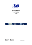
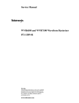
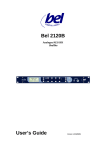
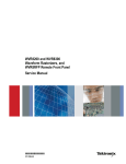
BM A2-E8SHD+ 8 Channel Digital Audio Monitor User’s Guide Version 1.0 09/05/2008 BEL DIGITAL AUDIO BM A2-E8SHD BEL (Digital Audio) Ltd. has made every effort to ensure the accuracy of information contained within this document which is nevertheless supplied for information purposes only and does not constitute any form of warranty or guarantee. All trademarks acknowledged. The information in this document is subject to change without notice. Bel Digital Audio Ltd. Unit 3 Horwood Court Bletchley Milton Keynes Bucks MK11RD Tel: 01908-641063 Email: [email protected] Web: www.beldigital.com 2006 BEL (Digital Audio) Ltd BEL DIGITAL AUDIO BM A2-E8SHD Contents INTRODUCTION Main features Typical LCD displays Bargraph scales OPERATION SELECTING SOURCES AES input mode SDI input mode Dolby mode USING THE PROGRAM SWITCH DIRECTING SOURCES TO SPEAKERS REAR PANEL AUDIO OUTPUTS USING THE LCD PHASE DISPLAY METADATA DISPLAY INSTALLATION CONNECTOR I/O RS232 Dolby interface connector pinout Analogue audio outputs CONFIGURATION Adjusting audio monitor output level Adjusting bargraph break-points and ballistics Inserting bargraph graticules 1 2 3 3 4 4 4 4 5 5 6 7 8 9 10 10 10 11 11 13 13 16 QUESTIONS AND ANSWERS 18 APPENDIX A 19 SPECIFICATION 21 2006 BEL (Digital Audio) Ltd BEL DIGITAL AUDIO BM A2-E8SHD Introduction Introduction The BM A2-E8SHD+ is a 2U high quality eight-channel audio monitor with an integral Dolby® decoder. The unit accepts audio from either one of two AES inputs or one of two SDI inputs and produces four pairs of AES and analogue outputs. The SDI inputs automatically detect SD or HD video and demultiplex 8 audio channels. Two active loop through outputs are available for the SDI inputs. Stick-on scale graticules, which may be applied to the spaces between the front-panel bargraphs, are supplied with the machine. The LCD display shows the status of the selected audio or Dolby program and can also be used to display phase information. The BEL Digital BM A2-E8SHD+ The headphone output is taken before the limiters and mutes the speakers when used. A soft mute is applied to the audio when any select switches are used to reduce glitches. 2006 BEL (Digital Audio) Ltd 1 Version 1.0 BEL DIGITAL AUDIO BM A2-E8SHD Introduction Eight high-resolution tri colour bar graphs are provided with user selectable ballistics and colour break points. Up to eight de-embedded or Dolby E decoded audio inputs can be selected individually or mixed and directed to each speaker. Bargraph meters are arranged in two groups of four, the left hand group handles inputs 1 to 4 and the right hand group handles inputs 5 to 8. Each bargraph group can be configured for different meter types and scales and have different colours for level transition points. The Dolby decoder decodes Dolby D or Dolby E from the AES inputs or from any group of the SDI embedded audio. Dolby E is implemented using two operational modes; ‘Independent’ where all eight channels are available and Dolby Mix-Down or ‘Program’ mode where a selected mix of channels is available according to the encoding used. An example would be 5.1 +1 +1, where three ‘programs’ are available; the 5.1 mix down and the two additional programs, +1 and +1. In Independent mode an 8 x 2 matrix allows any of the Dolby E decoded channels to be fed to either or both of the left or right analogue audio output channels. This special mix-down facility allows a stereo version of a complete Dolby E encoded signal to be heard for all programs. This is particularly helpful with Dolby E encoded signals where up to 8 audio signals of a surround sound + source can be heard using individual audio elements or a complete aural impression by summing some or all of the channels. The eight audio channels selected are also output at the rear of the unit as four pairs of AES signals on BNC connectors and four pairs of differential analogue signals. The analogue outputs can be at a fixed level or slaved to the front panel volume control. Main features • Balanced (XLR) and unbalanced (BNC) digital audio (AES) inputs • Two auto-sensing SD/HD inputs with loop through • Dolby® D or Dolby® E decoder • Dolby mix-down program select switch • Custom channel mix-downs for de-embedded multiple audio and Dolby E independent mode • Two groups of four tri-colour bargraphs with different meter types/ballistics, colour transition points, peak-hold and brightness settings for each group • Analogue line output and 8 selected audio outputs • Six different meter types: AES/EBU, Nordic, DIN, VU, Extended VU and BBC • LCD status/phase display • Headphone connector with speaker mute • RS232 port for Dolby decoder remote control 2006 BEL (Digital Audio) Ltd 2 Version 1.0 BEL DIGITAL AUDIO BM A2-E8SHD Introduction Typical LCD displays Dolby® status The LCD display will show general status information related to the currently selected input such as the source selected and line standard. If a Dolby input is selected and the Dolby decoder is enabled, further Dolby information will be shown as illustrated above. Phase display The bar graph shows the phase relationship of two selected inputs. See the Operation chapter for more information. Bargraph scales The following meter types may be selected using internal switches. Scale type Range Attack Fallback AES/EBU: 60dB (0 to -60dB) 1ms 1.5Sec per 20dB decay DIN PPM: 55dB (+5 to -50dB) 10mSec 1.5Sec per 20dB decay VU: 23dB (+3 to -20dB) 300mSec 300mSec VU EXT: 80dB (+20 to -60dB) 300mSec 300mSec BBC PPM: +12 to-12dB - mark 7 to 1 10mSec 2.85Sec - mark 7 to 1 NORDIC: 54dB (+12 to -42dB) 5mSec 1.7Sec per 20dB decay BM A2-E8SHD+ meter types Note: Refer to the Installation chapter for bargraph settings and graticule/scale fitting instructions. 2006 BEL (Digital Audio) Ltd 3 Version 1.0 BEL DIGITAL AUDIO BM A2-E8SHD Operation Operation The BM A2-E8SHD+ front panel Selecting sources The input source select switch determines which source (AES1, AES2, SDI 1 or SDI 2) is available to the Dolby decoder, speaker selectors and bargraphs. Repeatedly press the source select button until the required LED is illuminated. Two source settings are retained over power down, one for Dolby mode and one for direct mode. Source LEDs are lit red until a valid source is connected when the corresponding LED will turn green. AES input mode In the AES input mode the mix buttons are inoperative and the left speaker is selected as left input and right speaker the right input. The input level is shown on the left two bargraphs. Note: AES inputs can be at 48kHz or 44.1kHz sampling rate. SDI input mode The unit automatically detects SD or HD video and shows the video mode on the LCD (525,625,720 or 1080). Two groups will be demuxed to give 8 audio signals. The groups are selected using the A and B group select switches. Note: The LCD display will indicate if a Dolby signal is present, but the signal will not be decoded unless Dolby mode is active. 2006 BEL (Digital Audio) Ltd 4 Version 1.0 BEL DIGITAL AUDIO BM A2-E8SHD Operation The left 4 bar graphs show the audio in the group selected by the A group switch. The right 4 bar graphs show the audio in the group selected by the B group switch. Dolby mode To enable the Dolby decoder, press the Dolby button until the Dolby light is illuminated. The unit will decode Dolby D and Dolby E from the AES inputs or embedded audio carried in an SD or HD SDI signal. Dolby E encoding allows several separate ‘programs’ or groups of audio to be carried in the same data stream. The program switch is provided to allow the individual programs to be selected and their channels directed to bargraphs. See the section entitled, Using the program switch for more information about the Dolby E monitoring features available. Decoding AES inputs Rotate the Dolby program mix switch to the independent position. The unit will automatically detect and decode the Dolby signals and show up to 8 audio signals on the bargraphs. The type of Dolby encoding will be shown on the display. Decoding SDI inputs Dolby E or Dolby D embedded in a pair of audio signals in an SDI stream can be decoded and up to eight audio signals can be shown on the bargraphs. The type of Dolby encoding will be shown on the display. Select the channel pair carrying the Dolby encoded signal using the Dolby group select rotary switch. So for example if the Dolby signal was encoded in the second pair of audio signals in group 1 this corresponds to channels 3/4 and is selected by rotating the Dolby group select switch to position 2. Using the program switch Dolby E encoding allows several separate ‘programs’ or groups of audio to be carried in the same data stream. The program switch allows individual mix-downs and channels within a Dolby E program to be monitored. Available mix downs are selected with the Program Switch as shown in the switch position table in Appendix A. The selected signal is sent to the left and right speakers and the first two bargraphs (left most looking at the front of the unit). The following example may help to explain the facilities provided. Consider the situation where a studio wants to convey a surround sound music signal together with two technical 2006 BEL (Digital Audio) Ltd 5 Version 1.0 BEL DIGITAL AUDIO BM A2-E8SHD Operation commentaries for transmitter operators. For the surround sound a 5.1 configuration might be ideal since it has 5 audio channels and one LF effects channel as shown in Appendix A. However, the two independent engineering feeds (two different languages and not for transmission) can be encoded into two unused channels to give a configuration of 5.1+1+1. The Dolby mix-down The operator at the transmitter might want to listen to the music but not necessarily in full surround sound. Fortunately, the Dolby decoder has an auxiliary output which carries a mixdown. This is a stereo signal that contains a mixture of, in this case, all 6 music signals with any phasing or special effect applied. The Dolby decoder ‘knows’ that the audio is encoded as 5.1+1+1. In order to listen to the engineering feeds it must be possible to direct the decoder to select the 5.1, +1 or +1 signals and output the appropriate mix-down to the auxiliary output. The three separately encoded audio ‘programs’ can se selected using the Program Switch. Clearly the mix-down of the +1 signals will be a simple mono signal. When the BM A2-E8SHD+ is in any of the P1 to P8 Program Select modes (or Dolby DownMix modes), the stereo audio available on the auxiliary output is sent to the left and right speakers and to bar graphs 1&2. Refer to appendix A for a list of the available Dolby programs and channels for specific Dolby E Program Sequences. Note: The speaker select/mix facility is defeated in Program Select or Dolby Down-Mix modes. Independent mode All of the Dolby E audio signals can be decoded and made available on their own (not mixed) by setting the Program Switch to the Independent position. In the 5.1 +1 +1 example music might be presented on bar graphs 1 to 6 and the two engineering feeds on bars 7 and 8. It is then easy to select which of these to listen to by pressing the button under the appropriate bar graph. A mix down of some or all of the channels can be obtained by selecting several audio signals to be sent to each speaker. Note: Independent mix-down does not apply all of the phasing effects of the Dolby mix-down modes. Directing sources to speakers Where more than two audio signals are present (i.e. Dolby E independent mode or deembedded mode), it may be useful to direct and combine sources to selected speakers. To develop a mix-down of chosen sources for left or right speakers proceed as follows: • Left channel mix: press the left speaker select button, LS, until the LED above the button shows red. Then press the button under the bar graph corresponding to the input audio signal required. The buttons toggle and if more than one button is 2006 BEL (Digital Audio) Ltd 6 Version 1.0 BEL DIGITAL AUDIO BM A2-E8SHD Operation pressed the audio signals will be summed. The left speaker audio output level is automatically adjusted to compensate for the mixing process. The selected audio is indicated by the LED above the corresponding bar graph turning red. • Right channel mix: press the right speaker select button, RS, until the LED above the button shows green. Then press the button under the bar graph corresponding to the input audio signal required. The buttons toggle and if more than one button is pressed the audio signals will be summed. The right speaker audio output level is automatically adjusted to compensate for the mixing process. The selected audio is indicated by the LED above the corresponding bar graph turning green. • If an input is directed to both left and right speakers the indicating LED is illuminated in amber. Note that the setting of the mix buttons is retained over power down. There are two sets of memories one for the Dolby mode and one for the independent mode. The appropriate set is automatically selected depending on the current mode. (Changed using the Dolby button) Rear panel audio outputs The BM A2-E8SHD+ provides digital and analogue audio outputs on the rear panel. Eight differential analogue on a 25 way ‘D’ type connector and four pairs of AES3 on BNC connectors are available. The audio carried on these is derived from the currently selected eight audio sources. In effect these audio outputs are a copy of the signals shown on the unit’s bar graphs. They can thus be a copy of the AES inputs, the two currently demuxed SDI groups or the eight decoded Dolby signals. The level of the analogue outputs is adjustable in one of two ways as dictated by link LK5 on the PCB. In the position shown in the picture the analogue output level can be set using the control RV1 on the PCB this is factory set to be 0dB for an analogue bar graph level of 0dB. With the link in the other position the level of the analogue outputs will follow the setting of the main volume control. It is possible to mute the output from the unit’s speakers by removing all the mix button selections. 2006 BEL (Digital Audio) Ltd 7 Version 1.0 BEL DIGITAL AUDIO BM A2-E8SHD Operation Using the LCD phase display To enter the phase display mode ensure both LS and RS LED are extinguished. Then press and hold the button under the input signal required to be the phase reference. Press and hold the input button to be the variable phase input. The display will show the phase of the selected signals. Phase display The bar graph on the lower half of the display shows the phase shift between two selected inputs. It works best for none periodic signals such as music or noise. If the phase calculation detects a complete phase inversion the word inv is shown. Release the buttons to return the display to the normal screen. 2006 BEL (Digital Audio) Ltd 8 Version 1.0 BEL DIGITAL AUDIO BM A2-E8SHD Operation MetaData Display The BM A2-E8SHD+ is capable of displaying comprehensive Dolby E and D metadata information. It is recommended that this section be read in conjunction with the Dolby Metadata guide issue 3. To enter the metadata display mode use the following sequence: 1. Ensure that a valid Dolby encoded source is connected, selected and decoding correctly. 2. For Dolby E metadata select the program number required using the front panel rotary switch prior to entering the metadata display mode. The unit will default to program 1 if the independent position is active. 3. Press and hold the Dolby button for more than two seconds. The BM A2-E8SHD+ will then enter the Dolby decode mode and will briefly show “metadata display” on the LCD. The display will index to the next available metadata each time the Dolby button is pressed. To exit the metadata display mode press any other button. There are three routes through the metadata display depending on the source format 1. PCM. The display will show PCM and the exit on the next button press. 2. Dolby D. The display will show the Dolby Digital metadata. 3. Dolby E. The display will show the metadata for the currently selected program. If parts of the metadata are not available a warning is shown and the missing metadata will not be displayed. (e.g. Audio production information not present, mix level and room type not shown). Typical Metadata display Note. The Dolby decoder card (CAT552) currently used in the BM A2-E8SHD+ does not carry all metadata. As these become available software upgrades will be announced. 2006 BEL (Digital Audio) Ltd 9 Version 1.0 BEL DIGITAL AUDIO BM A2-E8SHD Installation Installation The BM A2-E8SHD+ is designed to be installed in 19 inch bays on an equipment tray. Ventilation is by natural convection. Connector I/O The balanced AES digital audio input uses a balanced XLR connector and the unbalanced AES digital audio (SPDIF compatible) I/O uses BNC connectors. SDI use BNC connectors and the analogue monitor line outputs use balanced XLRs. The analogue outputs are provided on a 25 way ‘D’ connector. An RS232 connector is provided for remote programming of the Dolby decoder. The BM A2-E8SHD+ rear view RS232 Dolby interface connector pinout Connector type: 9 way D female Speed: 9600 bps Format: 8 bit, no parity, 2 stop bits Pin 1 Description Not connected 2 Rx (from host) 3 Tx (to host) 4 Not connected 5 GND 6 Not connected 7 Not connected 8 Not connected 9 Not connected Note: A standard modem lead can be used to interface to a PC. 2006 BEL (Digital Audio) Ltd 10 Version 1.0 BEL DIGITAL AUDIO BM A2-E8SHD Installation Analogue audio outputs Pin 1 Description Aout 1+ 2 Aout 1- 3 GND 4 Aout 2+ 5 Aout 2- 6 GND 7 Aout 3+ 8 Aout 3- 9 GND 10 Aout 4+ 11 Aout 4- 12 GND 13 GND 14 GND 15 Aout 5+ 16 Aout 5- 17 GND 18 Aout 6+ 19 Aout 6- 20 GND 21 Aout 7+ 22 Aout 7- 23 GND 24 Aout 8+ 25 Aout 8- Configuration Bargraph meters are supplied in two groups of four to monitor inputs 1 to 4 and inputs 5 to 8. These two groups of bargraphs may be configured independently to support different meter ballistics and scales, peak hold decay and different transition points between coloured areas. Different scales are supported with a range of stick on scale graticules and meter type settings are made inside the unit using DIL switches. 2006 BEL (Digital Audio) Ltd 11 Version 1.0 BEL DIGITAL AUDIO BM A2-E8SHD Installation Access to BM A2-E8SHD+ internal adjustments is obtained with the top removed. Note: 8 channel output interface omitted for clarity. Warning: Configuration instructions are for trained personnel. To avoid dangerous electric shock, do not remove any covers or carry out adjustments unless qualified to do so. BM A2-E8SHD+ internal adjustments The following adjustments may be made: • • • • • Warning: Analogue line output – SW1/potentiometers main board Bargraph settings – SW1/SW2 and SW4/3 on bargraph module Auto-sum LK6 Line Out Left, LK9 Line Out Right LCD contrast –potentiometer below bargraph module on main board LK1 and LK2 (under bargraph module) enable SDI loop out when jumper link is placed across pins. Improperly terminated or unterminated inputs or outputs will reduce usable cable length. Do not enable loop through unless terminations are in place. 2006 BEL (Digital Audio) Ltd 12 Version 1.0 BEL DIGITAL AUDIO BM A2-E8SHD Installation Adjusting audio monitor output level In the following tables, ON is obtained with a switch lever in the DOWN position. The adjustments are located on the main board under the output sub-board. Analogue monitor output adjustments – 0dB setting shown SW3 Note: 1 Monitor Output Left Setting when ON 0 dB (0 on analogue scale = 0dBu on output) 2 Left 4 dB (0 on analogue scale = +4dBu on output) 3 Left 8 dB(0 on analogue scale = +8dBu on output) 4 Left Variable – adjacent pot* 0 to +12 dB 5 Right 0 dB (0 on analogue scale = 0dBu on output) 6 Right 4 dB (0 on analogue scale = +4dBu on output) 7 Right 8 dB(0 on analogue scale = +8dBu on output) 8 Right Variable – adjacent pot* 0 to +12 dB It is intended that only one switch lever is set to ON for each monitor output. The ON position is obtained with a switch lever in the direction of the arrow (downward in the above drawing). Clockwise rotation increases gain. Adjusting bargraph break-points and ballistics 2006 BEL (Digital Audio) Ltd 13 Version 1.0 BEL DIGITAL AUDIO BM A2-E8SHD Installation The switch adjustments for each group of four bargraphs are as follows: • • Channels 1 to 4: use DIL switches SW1/1 to 8 and SW2/1 to 8 Channels 5 to 8: use DIL switches SW4/1 to 8 and SW3/1 to 8 BM A2-E8SHD+ bargraph adjustments AES to analogue adjust 3-18dBFS = 0 on analogue scale -20dBFS = 0 on analogue scale SW 1(4)/8 ON OFF The –18dB and –20dB settings define the relationship between AES input level and the 0 mark on an analogue scale. This allows analogue scales to be used with digital signals. Note: When digital inputs are used with an analogue scale line outputs are less than shown on the meters since digital to analogue converters clip at +15 dB. The effective loss is -3dB when the 18 dB position is selected and -5dB when the 20 dB position is selected. Peak hold decay None (Off) 3 seconds 7 seconds Indefinite Scale type AES DIN VU BBC Extended VU NORDIC No scale No scale Note: SW1(4)/7 OFF OFF ON ON SW1(4)/5 OFF OFF OFF OFF ON ON ON ON SW1(4)/6 OFF ON OFF ON SW1(4)/4 OFF OFF ON ON OFF OFF ON ON SW1(4)/3 OFF ON OFF ON OFF ON OFF ON The ON position is obtained with a switch lever DOWN in the drawing. Each bargraph has 53 tri-colour segments. The top and bottom segments are reserved leaving 51. Up to 31 of the remaining top most segments may be coloured red. Up to 31 of segments from the end of the red zone downward may be coloured amber. The remaining segments (if any) are always green. 2006 BEL (Digital Audio) Ltd 14 Version 1.0 BEL DIGITAL AUDIO BM A2-E8SHD Installation Red zone Choosing how many segments are coloured red from the top of the bargraph sets the ‘red zone’. Select from none to 31 using SW1(4)/2, SW1(4)/1, SW2(3)/8, SW2(3)/7 and SW2(3)/6 as follows: Segment from bargraph top None 1 2 3 4 5 6 7 8 9 10 11 12 13 14 15 16 17 18 19 20 21 22 23 24 25 26 27 28 29 30 31 Note: SW1(4)/2 OFF OFF OFF OFF OFF OFF OFF OFF OFF OFF OFF OFF OFF OFF OFF OFF ON ON ON ON ON ON ON ON ON ON ON ON ON ON ON ON SW1(4)/1 OFF OFF OFF OFF OFF OFF OFF OFF ON ON ON ON ON ON ON ON OFF OFF OFF OFF OFF OFF OFF OFF ON ON ON ON ON ON ON ON SW2(3)/8 OFF OFF OFF OFF ON ON ON ON OFF OFF OFF OFF ON ON ON ON OFF OFF OFF OFF ON ON ON ON OFF OFF OFF OFF ON ON ON ON SW2(3)/7 OFF OFF ON ON OFF OFF ON ON OFF OFF ON ON OFF OFF ON ON OFF OFF ON ON OFF OFF ON ON OFF OFF ON ON OFF OFF ON ON SW2(3)/6 OFF ON OFF ON OFF ON OFF ON OFF ON OFF ON OFF ON OFF ON OFF ON OFF ON OFF ON OFF ON OFF ON OFF ON OFF ON OFF ON It is not possible to set 31 red and 31 amber segments, since there are only 51 segments for level display purposes. Amber zone Choosing how many segments are coloured amber from the end of ‘red zone’ sets the ‘amber zone’. Select from none to 31 using SW2(3)/5, SW2(3)/4, SW2(3)/3, SW2(3)/2 and SW2(3)/1 as follows: 2006 BEL (Digital Audio) Ltd 15 Version 1.0 BEL DIGITAL AUDIO Segment from last RED ZONE None 1 2 3 4 5 6 7 8 9 10 11 12 13 14 15 16 17 18 19 20 21 22 23 24 25 26 27 28 29 30 31 BM A2-E8SHD SW2(3)/5 OFF OFF OFF OFF OFF OFF OFF OFF OFF OFF OFF OFF OFF OFF OFF OFF ON ON ON ON ON ON ON ON ON ON ON ON ON ON ON ON SW2(3)/4 OFF OFF OFF OFF OFF OFF OFF OFF ON ON ON ON ON ON ON ON OFF OFF OFF OFF OFF OFF OFF OFF ON ON ON ON ON ON ON ON Installation SW2(3)/3 OFF OFF OFF OFF ON ON ON ON OFF OFF OFF OFF ON ON ON ON OFF OFF OFF OFF ON ON ON ON OFF OFF OFF OFF ON ON ON ON SW2(3)/2 OFF OFF ON ON OFF OFF ON ON OFF OFF ON ON OFF OFF ON ON OFF OFF ON ON OFF OFF ON ON OFF OFF ON ON OFF OFF ON ON SW2(3)/1 OFF ON OFF ON OFF ON OFF ON OFF ON OFF ON OFF ON OFF ON OFF ON OFF ON OFF ON OFF ON OFF ON OFF ON OFF ON OFF ON Inserting bargraph graticules The following bargraph scale graticules are supplied with each unit: 2006 BEL (Digital Audio) Ltd 16 Version 1.0 BEL DIGITAL AUDIO BM A2-E8SHD Installation BM A2-E8SHD+ scale graticules To apply a graticule proceed as follows: • • • peel back the protective backing from the chosen graticule apply the graticule to the space between a pair of bargraphs repeat the process for the other bargraph graticule position • • ensure that the bargraph setting matches the graticule adjust the colour transitions and peak hold decay as desired 2006 BEL (Digital Audio) Ltd 17 Version 1.0 BEL DIGITAL AUDIO BM A2-E8SHD Questions and answers Questions and answers The unit seems dead, what can I do? Check the power cabling and the integral fuse in the IEC mains socket at the rear of the unit. Check that the power switch at the rear is in the on position. Try using a different known power source. Try switching the unit off at the rear for a few seconds and then restore power. For some bargraph displays, ballistics or colour transition points are wrong, what can I do? Check that the appropriate meter type and colour transition points have been selected with the DIL switches inside the unit. Check that the chosen ballistics setting and bargraph scale graticules match. Why do one or more input source LEDs remain red? For all inputs check that a valid input is present at the rear of the unit. For SD/HD inputs check that high quality cable is used and that 75Ω terminations are in place if loop through outputs are enabled. LK1 or LK2 (under bargraph module) enabled loop through when placed across pins; in this position the loop through output must be properly terminated. For AES inputs check that the input sample rate is 48.kHz. Why don’t the mix-assign buttons work in any Dolby E program mode? When the Program Switch is in positions P1 to P8 the Dolby decoder is responsible for producing the required mix-downs in a Dolby E Program Sequence. The individual channels that go to make the sequence components are not available and the mix-assign and speaker buttons are disabled. What exactly does the Program Switch do? The Program Switch works when the Dolby decoder is active and receiving a Dolby E bistream. It allows a particular component in a Dolby E bitstream to be selected and sent as a stereo signal to the unit’s speakers the left-most two bargraphs. What do the mix assign and left right speaker buttons do? These buttons are enabled whenever more than two audio signals are available in Dolby E independent mode and de-embedded mode. The buttons underneath the bargraphs work with the left/right speaker buttons to control an 8x2 mixer. This allows up to eight audio channels to be assigned to the left or right audio output channels and so allow custom mix-downs. It does not affect signals sent to the bargraphs. What is the RS232 port for? This is provided in accordance with Dolby licence requirements to allow Dolby decoder firmware to be updated. 2006 BEL (Digital Audio) Ltd 18 Version 1.0 BEL DIGITAL AUDIO BM A2-E8SHD Appendix A Appendix A The following table shows all the possible Dolby E Program Configurations or Dolby Digital Coding modes supported by the unit and what each of the eight channels carries. Main Output Channel Assignment Dolby modes Ch1 Ch2 Ch3 Ch4 Ch5 Ch6 Ch7 Ch8 5.1+2 1L 1R 1C 1LFE 1Ls 1Rs 2L 2R 5.1+1+1 1L 1R 1C 1LFE 1Ls 1Rs 2C 3C 4+4 1L 1R 1C 1S 2C 2S 2L 2R 4+2+2 1L 1R 1C 1S 3L 3R 2L 2R 4+2+1+1 1L 1R 1C 1S 3C 4C 2L 2R 4+1+1+1+1 1L 1R 1C 1S 4C 5C 2C 3C 2+2+2+2 1L 1R 3L 3R 4L 4R 2L 2R 2+2+2+1+1 1L 1R 3L 3R 4C 5C 2L 2R 2+2+1+1+1+1 1L 1R 3C 4C 5C 6C 2L 2R 2+1+1+1+1+1+1 1L 1R 4C 5C 6C 7C 2C 3C 1+1+1+1+1+1+1+1 1C 2C 3C 4C 5C 6C 7C 8C 5.1 1L 1R 1C 1LFE 1Ls 1Rs None None 4+2 1L 1R 1C 1S None None 2L 2R 4+1+1 1L 1R 1C 1S None None 2C 3C 2+2+2 1L 1R 3L 3R None None 2L 2R 2+2+1+1 1L 1R 3C 4C None None 2L 2R 2+1+1+1+1 1L 1R 4C 5C None None 2C 3C 1+1+1+1+1+1 1C 2C 3C 4C 5C 6C None None 4 1L 1R 1C 1S None None None None 2+2 1L 1R None None None None 2L 2R 2+1+1 1L 1R None None None None 2C 3C 1+1+1+1 1C 2C 3C 4C None None None None 3/2L 1L 1R 1C 1LFE 1Ls 1Rs None None 3/2 1L 1R 1C None 1Ls 1Rs None None 2/2L 1L 1R None 1LFE 1Ls 1Rs None None 2/2 1L 1R None None 1Ls 1Rs None None 3/1L 1L 1R 1C 1LFE 1S None None None 3/1 1L 1R 1C None 1S None None None 2/1L 1L 1R None 1LFE 1S None None None 2/1 1L 1R None None 1S None None None 3/OL 1L 1R 1C 1LFE None None None None 3/0 1L 1R 1C None None None None None 2/0 1L 1R None None None None None None 1/0 None None 1C None None None None None 1+1 1C 2C None None None None None None PCM 1L 1R None None None None None None 2006 BEL (Digital Audio) Ltd 19 Version 1.0 BEL DIGITAL AUDIO BM A2-E8SHD Appendix A The following table shows all the possible Dolby E Program Sequences and relates them to the number of available channels and programs. The mix down within a sequence can be selected with the Program Switch in the positions shown. The selected mix down is sent to the left and right speakers and the first two bargraphs (left most looking at the front of the unit). Chs Pgms 5.1+2 8 2 P1: 5.1, P2:+2 5.1+1+1 8 3 P1: 5.1, P2:+1, P3:+1 4+4 8 2 P1: 4, P2:+4 4+2+2 8 3 P1: 4, P2:+2, P3:+2 4+2+1+1 8 4 P1: 4, P2:+2, P3:+1, P4+1 4+1+1+1+1 8 5 P1: 4, P2:+1, P3:+1, P4+1, P5+1 2+2+2+2 8 4 P1:2, P2:+2, P3:+2, P4:+2, 2+2+2+1+1 8 5 P1:2, P2:+2, P3:+2, P4:+1, P5:+1 2+2+1+1+1+1 8 6 P1:2, P2:+2, P3:+1, P4:+1, P5:+1, P6:+1 2+1+1+1+1+1+1 8 7 P1:2, P2:+1, P3:+1, P4:+1, P5:+1, P6:+1, P7:+1 1+1+1+1+1+1+1+1 8 8 P1:1, P2:+1, P3:+1, P4:+1, P5:+1, P6:+1, P7:+1, P8:+1 5.1 8 1 P1: 5.1 4+2 6 2 P1: 4, P2:+2 4+1+1 6 3 P1: 4, P2:+1, P3:+1 2+2+2 6 3 P1: 2, P2:+2, P3:+2 2+2+1+1 6 4 P1: 2, P2:+2, P3:+1, P4:+1 2+1+1+1+1 6 5 P1: 2, P2:+1, P3:+1, P4:+1, P5:+1 1+1+1+1+1+1 6 6 P1: 1, P2:+1, P3:+1, P4:+1, P5:+1, P6:+1 4 4 1 P1:4 2+2 4 2 P1:2, P2:+2, 2+1+1 4 3 P1: 2, P2:+1, P3:+1 1+1+1+1 4 4 P1:1, P2:+1, P3:+1, P4:+1 Dolby mode Note: Program Switch The Program Switch selects sequence elements in the order they appear in the Dolby E bit stream. For example for 5.1+1+1, P1 selects 5.1, P2 selects the first +1 additional channel and P3 selects the final +1 additional channel. 2006 BEL (Digital Audio) Ltd 20 Version 1.0 BEL DIGITAL AUDIO BM A2-E8SHD Specification Specification Audio inputs Digital AES Sample rate 1 x 110Ω differential (XLR connector) and 1 x 75Ω (BNC connector) 48.kHz. Video Input 2 x SD/HD SMPTE 259M, 296M, 274M, 292M Meters Bar Graphs 53 element tricolour with adjustable colour break points Analogue monitor outputs Max output level +15dB Noise +THD -98dB Frequency response All analogue outputs 20 Hz to 20kHz ±1dB Selected Analogue outputs 8 differential on 25 way ‘D’ type connector Noise+thd -108dB w.r.t clipping Output level At max volume setting +10dB At 0.5 volume setting –2dB AES outputs 4 pairs unbalanced on BNC connectors Main drive amp Noise +THD -80dB w.r.t. maximum output Speaker driver units Peak acoustic level (@2ft) Shielding 100dB SPL Magnetic Scales and Ballistics 2006 BEL (Digital Audio) Ltd 21 Version 1.0 BEL DIGITAL AUDIO BM A2-E8SHD NORDIC: Specification Overall dynamic range: 54dB (+12 to -42dB) Attack time: 5mSec Fallback: 1.7Sec per 20dB decay DIN PPM: Overall dynamic range: 55dB (+5 to -50dB) Attack time: 10mSec Fallback: 1.5Sec per 20dB decay BBC PPM: Overall dynamic range: (+12 to-12dB from mark 7 to mark 1) Attack time: 10mSec Fallback: 2.85Sec (from mark 7 to mark 1) VU: Overall dynamic range: 23dB (+3 to -20dB) Attack time: 300mSec Fallback: 300mSec VU EXT: Overall dynamic range: 80dB (+20 to -60dB) Attack time: 300mSec Fallback: 300mSec AES/EBU: Overall dynamic range: 60dB (0 to -60dB) Attack time: 1mSec Fallback: 1.5Sec per 20dB decay Housing 19” Rack Mount: 2U high. Outline Dimensions: 483mm(W) x 256mm(D) x 89mm(H) Outline Dimensions: 19inch(W) x 10inch(D) x 3.5inch(H) Power 90 - 264 VAC 50/60Hz Autoselect, Fuse 4A HAC Environmental Temperature 0°C to 30°C Humidity 70% max (non-condens ing) Weight 6kg (14lbs) Computer interface 9 pin RS-232 female PC-AT serial interface for Dolby card 2006 BEL (Digital Audio) Ltd 22 Version 1.0