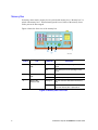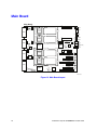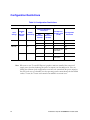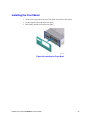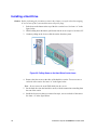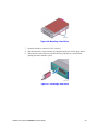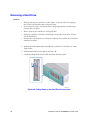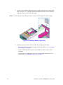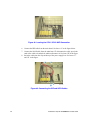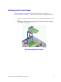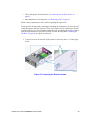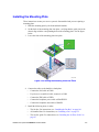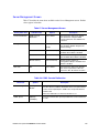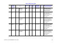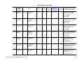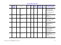
1
Intel® Server System
SR9000MK4U Product Guide
Intel Order Number D71314-003
Disclaimer
Information in this document is provided in connection with Intel® products. No license, express or implied, by
estoppel or otherwise, to any intellectual property rights is granted by this document. Except as provided in Intel's
Terms and Conditions of Sale for such products, Intel assumes no liability whatsoever, and Intel disclaims any
express or implied warranty, relating to sale and/or use of Intel products including liability or warranties relating to
fitness for a particular purpose, merchantability, or infringement of any patent, copyright or other intellectual property
right. Intel products are not designed, intended or authorized for use in any medical, life saving, or life sustaining
applications or for any other application in which the failure of the Intel product could create a situation where
personal injury or death may occur. Intel may make changes to specifications and product descriptions at any time,
without notice.
Intel server boards contain a number of high-density VLSI and power delivery components that need adequate
airflow for cooling. Intel's own chassis are designed and tested to meet the intended thermal requirements of these
components when the fully integrated system is used together. It is the responsibility of the system integrator that
chooses not to use Intel developed server building blocks to consult vendor datasheets and operating parameters to
determine the amount of airflow required for their specific application and environmental conditions. Intel Corporation
can not be held responsible if components fail or the server board does not operate correctly when used outside any
of their published operating or non-operating limits.
Intel, Intel Pentium, and Intel Xeon are trademarks or registered trademarks of Intel Corporation or its subsidiaries in
the United States and other countries.
* Other names and brands may be claimed as the property of others.
Copyright © 2006, Intel Corporation. All Rights Reserved
ii
Intel® Server System SR9000MK4U Product Guide
Safety Information
Important Safety Instructions
Read all caution and safety statements in this document before performing any of the
instructions. See also Intel Server Boards and Server Chassis Safety Information on the
Intel® Server Deployment Toolkit 2.0 CD and/or at http://support.intel.com/support/
motherboards/server/sb/cs-010770.htm.
Wichtige Sicherheitshinweise
Lesen Sie zunächst sämtliche Warnund Sicherheitshinweise in diesem Dokument, bevor
Sie eine der Anweisungen ausführen. Beachten Sie hierzu auch die Sicherheitshinweise zu
Intel-Serverplatinen und Servergehäusen auf der Intel® Server Deployment Toolkit 2.0 CD
oder unter http://support.intel.com/support/motherboards/server/sb/cs-010770.htm.
Consignes de sécurité
Lisez attention toutes les consignes de sécurité et les mises en garde indiquées dans ce
document avant de suivre toute instruction. Consultez Intel Server Boards and Server
Chassis Safety Information sur le Intel® Server Deployment Toolkit 2.0 CD ou bien
rendez-vous sur le site http://support.intel.com/support/motherboards/server/sb/cs010770.htm.
Instrucciones de seguridad importantes
Lea todas las declaraciones de seguridad y precaución de este documento antes de realizar
cualquiera de las instrucciones. Vea Intel Server Boards and Server Chassis Safety
Information en el Intel® Server Deployment Toolkit 2.0 CD y/o en http://
support.intel.com/support/motherboards/server/sb/cs-010770.htm.
iii
重要安全指导
Warnings
Heed safety instructions: Before working with your server product, whether you are
using this guide or any other resource as a reference, pay close attention to the safety
instructions. You must adhere to the assembly instructions in this guide to ensure and
maintain compliance with existing product certifications and approvals. Use only the
described, regulated components specified in this guide. Use of other products /
components will void the UL listing and other regulatory approvals of the product and
will most likely result in noncompliance with product regulations in the region(s) in which
the product is sold.
System power on/off: The power button DOES NOT turn off the system AC power. To
remove power from system, you must unplug the AC power cord from the wall outlet.
Make sure the AC power cord is unplugged before you open the chassis, add, or remove
any components.
Hazardous conditions, devices and cables: Hazardous electrical conditions may be
present on power, telephone, and communication cables. Turn off the server and
disconnect the power cord, telecommunications systems, networks, and modems attached
to the server before opening it. Otherwise, personal injury or equipment damage can
result.
Electrostatic discharge (ESD) and ESD protection: ESD can damage disk drives,
boards, and other parts. We recommend that you perform all procedures in this chapter
only at an ESD workstation. If one is not available, provide some ESD protection by
wearing an antistatic wrist strap attached to chassis ground any unpainted metal surface on
your server when handling parts.
ESD and handling boards: Always handle boards carefully. They can be extremely
sensitive to ESD. Hold boards only by their edges. After removing a board from its
protective wrapper or from the server, place the board component side up on a grounded,
static free surface. Use a conductive foam pad if available but not the board wrapper. Do
not slide board over any surface.
iv
Intel® Server System SR9000MK4U Product Guide
Installing or removing jumpers: A jumper is a small plastic encased conductor that slips
over two jumper pins. Some jumpers have a small tab on top that you can grip with your
fingertips or with a pair of fine needle nosed pliers. If your jumpers do not have such a tab,
take care when using needle nosed pliers to remove or install a jumper; grip the narrow
sides of the jumper with the pliers, never the wide sides. Gripping the wide sides can
damage the contacts inside the jumper, causing intermittent problems with the function
controlled by that jumper. Take care to grip with, but not squeeze, the pliers or other tool
you use to remove a jumper, or you may bend or break the pins on the board.
Intel® Server System SR9000MK4U Product Guide
v
vi
Intel® Server System SR9000MK4U Product Guide
Preface
About this Manual
Thank you for purchasing and using Intel® server products.
This manual is written for system technicians who are responsible for troubleshooting,
upgrading, and managing the Intel® Server System SR9000MK4U. This document
provides an overview of the features of the server system utilities, and instructions on how
to install, setup, and manage the system. For the latest version of this manual, see http://
support.intel.com/support/motherboards/server/SR9000MK4U/.
Manual Organization
Chapter 1 provides a brief overview of the chassis features for the Server System
SR9000MK4U.
Chapter 2 provides an overview of the features of the boards used in the Server System
SR9000MK4U.
In this chapter, you will find a list of the server board features, photos of the product, and
product diagrams to help you identify components and their locations.
Chapter 3 provides instructions for adding and replacing components. Use this chapter for
step-by-step instructions and diagrams for installing or replacing components such as the
hard drives, memory, processor, fans, boards and other components.
Chapter 4 tells you how to install the system into a rack environment.
Chapter 5 provides instructions on using the utilities that are shipped with the board or
that may be required to update the system. This includes how to navigate through the
BIOS Setup screens, and how to clear the CMOS.
Chapter 6 provides troubleshooting information. In this chapter, you will find suggestions
and steps to follow for performing troubleshooting activities to identify the source of a
problem.
Appendices provide tables of POST codes, SEL codes, safety information, safety start-up
warnings, and how to get help.
vii
Product Accessories
You may need or want to purchase one or more of the following accessory items for your
server:
Processor, memory DIMMs, hard drive, USB floppy drive, CD-ROM or DVD-ROM
drive, RAID controller, operating system.
For information about which accessories, memory, processors, and third-party hardware
have been tested and can be used with your board, and for ordering information for Intel
products, see http://support.intel.com/support/motherboards/server/SR9000MK4U/
compat.htm.
Additional Information and Software
If you need more information about this product or information about the accessories that
can be used with this server board, use the following resources. These files are available at
http://support.intel.com/support/motherboards/server/SR9000MK4U/
Unless otherwise indicated in the table below, once on this Web page, type the document
or software name in the search field at the left side of the screen and select the option to
search “This Product.”
Table 1. Additional Information and Software
For this information or
software
viii
Use this Document or Software
For in-depth technical
information about this
product, including BIOS
settings and chipset
information
Intel® Server System SR9000MK4U Technical Product
Specification
If you just received this
product and need to
install it
Intel® Server System SR9000MK4U Quick Start User's Guide in the
product box
Accessories or other Intel
server products
Spares and Configuration Guide
Hardware (peripheral
boards, adapter cards)
and operating systems
that have been tested with
this product
Tested Hardware Operating Systems List
Processors that have
been tested with this
product
Supported Processors
Intel® Server System SR9000MK4U Product Guide
Table 1. Additional Information and Software
For this information or
software
Use this Document or Software
DIMMs that have been
tested with this product
Tested Memory List
To make sure your system
falls within the allowed
power budget
Power Budget Tool
For software to manage
your Intel® server
TBD
For drivers
Driver (for an extensive list of available drivers)
Operating System Driver (for operating system drivers)
For firmware and BIOS
updates, or for BIOS
recovery
Firmware Updates
For diagnostics test
software
Diagnostics
See also the Intel® Server Deployment Toolkit 2.0 CD that came with your server system.
Intel® Server System SR9000MK4U Product Guide
ix
Powering the System On and Off
Powering On the System Power
1. Connect the power cables to AC input power connectors in the back of the system
and to the outlet. If 100 - 110 VAC is used, both power supplies must be connected.
2. If peripheral devices are attached that need to be turned on first, power on these
peripherals. See your peripheral guides for information.
3. Press the power button on the front panel. The green power LED will light.
4. Watch the fault LED on the front panel for any signs of trouble. See the
troubleshooting information at the end of this manual for help if necessary.
Powering Off the System Power
1. If peripheral devices are attached that need to be turned off first, power off these
peripherals. See your peripheral guides for information.
2. Press the power button on the front panel. The green power LED will turn off.
Note: The system will force a power off if the power button is held down for four or more
seconds. This method should be used only if the system has locked up. If the power is
forced off, wake events, such as Wake-on-LAN, are disabled. The IPMI “Power Off”
command functions the same way as a four-second button press. When the system power is
forced off, either the power button or the IPMI “Power On” command must be used to
power the system back on.
x
Intel® Server System SR9000MK4U Product Guide
Contents
Safety Information ..................................................................................................... iii
Important Safety Instructions ................................................................................................ iii
Wichtige Sicherheitshinweise ............................................................................................... iii
Consignes de sécurité .......................................................................................................... iii
Instrucciones de seguridad importantes ............................................................................... iii
Warnings ............................................................................................................................... iv
Preface ....................................................................................................................... vii
About this Manual ................................................................................................................ vii
Manual Organization ............................................................................................................ vii
Product Accessories ............................................................................................................viii
Additional Information and Software ....................................................................................viii
Powering the System On and Off .......................................................................................... x
Powering On the System Power .................................................................................... x
Powering Off the System Power .................................................................................... x
Chapter 1: Intel® Server System SR9000MK4U Chassis Overview ....................... 1
Chassis Description ............................................................................................................... 2
External Chassis Features ..................................................................................................... 3
Chassis Front ................................................................................................................ 4
Chassis Rear ................................................................................................................. 9
Internal Layout .............................................................................................................11
Internal Chassis Features ....................................................................................................12
Power Supply Subsystem ............................................................................................12
Cooling Subsystem ......................................................................................................14
PCI Card Slot ...............................................................................................................15
Chapter 2: Intel® Server System SR9000MK4U Board Set Overview .................. 17
Main Board ..........................................................................................................................18
Configuration Restrictions ...........................................................................................22
Processor Configurations ............................................................................................23
Memory Box Card ................................................................................................................24
DIMM Configurations ...................................................................................................25
Hard Drive Backplane ..........................................................................................................29
Hard Drive Population .................................................................................................30
Front Panel Board ................................................................................................................30
Chapter 3: Installing and Removing Components ................................................ 33
Tools Needed ......................................................................................................................33
Installing and Removing the Front Bezel .............................................................................34
Removing the Front Bezel ...........................................................................................34
Intel® Server System SR9000MK4U Product Guide
xi
Installing the Front Bezel ............................................................................................. 35
Installing and Removing the Top Cover .............................................................................. 36
Removing the Top Cover ............................................................................................ 36
Installing the Top Cover .............................................................................................. 37
Installing and Removing a Hard Drive ................................................................................. 37
Installing a Hard Drive ................................................................................................. 38
Removing a Hard Drive ............................................................................................... 40
Hot-swapping a Hard Drive ......................................................................................... 42
Installing and Removing a Memory Box .............................................................................. 42
Installing a Memory Box .............................................................................................. 43
Removing a Memory Box ............................................................................................ 45
Hot-swapping a Memory Box ...................................................................................... 46
Installing and Removing DIMMs .......................................................................................... 48
DIMM Installation Guidelines ...................................................................................... 48
Installing DIMMs .......................................................................................................... 49
Removing DIMMs ........................................................................................................ 50
Installing and Removing an Optical Drive ........................................................................... 51
Installing an Optical Drive ........................................................................................... 51
Removing the Optical Drive ........................................................................................ 53
Installing and Removing a Fan ............................................................................................ 55
Installing a Fan ............................................................................................................ 55
Removing a Fan .......................................................................................................... 57
Hot-swapping a Fan .................................................................................................... 58
Installing and Removing a PCI Card ................................................................................... 59
Installing a PCI Card ................................................................................................... 59
Removing a PCI Card ................................................................................................. 63
Hot-Plugging a PCI Card ............................................................................................. 67
Installing and Removing a Power Supply ............................................................................ 68
Installing a Power Supply ............................................................................................ 68
Removing a Power Supply .......................................................................................... 70
Hot-swapping a Power Supply .................................................................................... 73
Installing and Removing the Front Control Panel and Optical Drive Assembly ................... 74
Removing the Front Control Panel and Optical Drive Assembly ................................. 74
Installing the Front Control Panel and Optical Drive Assembly ................................... 75
Installing and Removing the Power Supply Box .................................................................. 76
Removing the Power Supply Box ................................................................................ 76
Installing the Power Supply Box .................................................................................. 80
Installing and Removing the Power Supply Support ........................................................... 83
Removing the Power Supply Support ......................................................................... 83
Installing the Power Supply Support ........................................................................... 85
Installing and Removing the Hard Drive Backplane Cover ................................................. 87
Removing the Hard Drive Backplane Cover ............................................................... 87
Installing the Hard Drive Backplane Cover ................................................................. 88
Installing and Removing the KVM Card .............................................................................. 89
xii
Intel® Server System SR9000MK4U Product Guide
Removing the KVM Card .............................................................................................89
Installing the KVM Card ...............................................................................................90
Installing and Removing the PCI Card Divider ....................................................................91
Removing the PCI Card Divider ..................................................................................91
Installing the PCI Card Divider ....................................................................................93
Installing and Removing the Air Flow Guide ........................................................................95
Removing the Air Flow Guide ......................................................................................95
Installing the Air Flow Guide ........................................................................................97
Installing and Removing the Fan Box ..................................................................................98
Removing the Fan Box ................................................................................................98
Installing the Fan Box ................................................................................................101
Installing and Removing the Hard Drive Backplane ..........................................................103
Removing the Hard Drive Backplane ........................................................................103
Installing the Hard Drive Backplane ..........................................................................107
Installing and Removing a Processor ................................................................................110
Removing a Processor ..............................................................................................111
Installing the Processor .............................................................................................113
Disassembling a Processor Assembly ...............................................................................122
Installing and Removing the Mounting Plate .....................................................................125
Removing the Mounting Plate ...................................................................................125
Installing the Mounting Plate .....................................................................................127
Installing and Removing Chassis Handles ........................................................................129
Installing Chassis Handles ........................................................................................129
Removing Chassis Handles ......................................................................................129
Chapter 4: Configuration Software and Utilities .................................................. 131
The Extensible Firmware Interface (EFI) Boot Manager ...................................................131
The Extensible Firmware Interface (EFI) Shell ..................................................................134
LSI* SAS Utility ..................................................................................................................137
Formatting a Hard Drive ............................................................................................137
Clearing the CMOS ............................................................................................................140
Upgrading the Firmware ....................................................................................................140
How to Use FWUPDATE ...........................................................................................142
Execution Screen ......................................................................................................144
Using System Setup ..........................................................................................................145
Starting Setup ............................................................................................................145
Recording Your Setup Settings .................................................................................145
Navigating Setup Utility Screens ...............................................................................146
Primary Screens ........................................................................................................146
Configuring Serial-Over LAN .............................................................................................150
Chapter 5: Troubleshooting .................................................................................. 153
Initial Troubleshooting Steps .............................................................................................153
Collecting System State Information ..................................................................................156
How to Read the POST Codes ..................................................................................159
Intel® Server System SR9000MK4U Product Guide
xiii
How to Use Selview to Read the System Event Log ................................................ 160
How to Collect System and Error Logs ..................................................................... 160
Taking Corrective Action ................................................................................................... 162
Appendix A: Console Setup ...................................................................................163
On-board VGA ................................................................................................................... 163
Serial Console ................................................................................................................... 165
Appendix B: Cabling ...............................................................................................167
Working with Ribbon Cables ............................................................................................. 167
Cable Connections ............................................................................................................ 168
Appendix C: POST Codes ......................................................................................171
Appendix D: Installation/Assembly Safety Instructions .....................................265
English ............................................................................................................................... 265
Deutsch ............................................................................................................................. 267
Français ............................................................................................................................. 269
Español ............................................................................................................................. 271
Italiano ............................................................................................................................... 273
Appendix E: Safety Information ............................................................................277
Warning Labels ................................................................................................................. 277
English ............................................................................................................................... 279
Server Safety Information ......................................................................................... 279
Safety Warnings and Cautions .................................................................................. 280
Intended Application Uses ........................................................................................ 280
Site Selection ............................................................................................................ 281
Equipment Handling Practices .................................................................................. 281
Power and Electrical Warnings ................................................................................. 282
System Access Warnings ......................................................................................... 283
Rack Mount Warnings ............................................................................................... 284
Electrostatic Discharge (ESD) ................................................................................... 284
Other Hazards ........................................................................................................... 284
Sicherheitshinweise für den Server ........................................................................... 286
Sicherheitshinweise und Vorsichtsmaßnahmen ....................................................... 286
Zielbenutzer der Anwendung .................................................................................... 287
Standortauswahl ....................................................................................................... 287
Handhabung von Geräten ......................................................................................... 288
Warnungen zu Netzspannung und Elektrizität .......................................................... 288
Warnhinweise für den Systemzugang ....................................................................... 289
Warnhinweise für Racks ........................................................................................... 290
Elektrostatische Entladungen (ESD) ......................................................................... 290
Andere Gefahren ....................................................................................................... 291
Français ............................................................................................................................. 292
Consignes de sécurité sur le serveur ........................................................................ 292
xiv
Intel® Server System SR9000MK4U Product Guide
Sécurité: avertissements et mises en garde ..............................................................292
Domaines d’utilisation prévus ....................................................................................293
Sélection d’un emplacement .....................................................................................293
Pratiques de manipulation de l’équipement ...............................................................293
Alimentation et avertissements en matière d’électricité .............................................294
Avertissements sur l’accès au système .....................................................................295
Avertissements sur le montage en rack ....................................................................296
Décharges électrostatiques (ESD) ............................................................................296
Autres risques ............................................................................................................296
Información de seguridad del servidor ......................................................................298
Advertencias y precauciones sobre seguridad ..........................................................298
Aplicaciones y usos previstos ....................................................................................299
Selección de la ubicación ..........................................................................................299
Manipulación del equipo ............................................................................................299
Advertencias de alimentación y eléctricas .................................................................300
Advertencias el acceso al sistema ............................................................................301
Advertencias sobre el montaje en bastidor ...............................................................302
Descarga electrostática (ESD) ..................................................................................302
Appendix F: Getting Help ...................................................................................... 309
World Wide Web ................................................................................................................309
Telephone ..........................................................................................................................309
Appendix G: Regulatory and Compliance Information ....................................... 313
Product Regulatory Compliance ........................................................................................313
Product Safety Compliance .......................................................................................313
Product EMC Compliance - Class A Compliance ......................................................314
Certifications / Registrations / Declarations ...............................................................314
Electromagnetic Compatibility Notices ..............................................................................315
FCC Verification Statement (USA) ............................................................................315
Industry Canada (ICES-003) .....................................................................................316
Europe (CE Declaration of Conformity) .....................................................................316
VCCI (Japan) .............................................................................................................316
BSMI (Taiwan) ...........................................................................................................317
RRL (Korea) ..............................................................................................................317
CNCA (CCC China) ...................................................................................................317
Regulated Specified Components .....................................................................................318
Restriction of Hazardous Substances (RoHS) Compliance ...............................................319
End of Life / Product Recycling ..........................................................................................319
Intel® Server System SR9000MK4U Product Guide
xv
xvi
Intel® Server System SR9000MK4U Product Guide
List of Figures
Figure 1. Intel® Server System SR9000MK4U Three Dimensional View.................................. 1
Figure 2. Chassis Front View .................................................................................................... 4
Figure 3. Front Panel Controls and Indicators........................................................................... 5
Figure 4. Optical Drive Bracket with Drive Installed .................................................................. 6
Figure 5. Hard Drive Carrier ...................................................................................................... 6
Figure 6. Memory Box Front View............................................................................................. 8
Figure 7. Chassis Rear View..................................................................................................... 9
Figure 8. Open System, Top View .......................................................................................... 11
Figure 9. Power Supply Indicators .......................................................................................... 13
Figure 10. Cooling Fan Indicator ............................................................................................. 14
Figure 11. PCI Card Slot Indicator .......................................................................................... 15
Figure 12. Block Diagram........................................................................................................ 17
Figure 13. Main Board Layout ................................................................................................. 18
Figure 14. Processor Locations............................................................................................... 23
Figure 15. Memory Box Card Layout ...................................................................................... 24
Figure 16. DIMM Locations (Top View of Memory Box).......................................................... 25
Figure 17. Memory Upgrade Path ........................................................................................... 28
Figure 18. Hard Drive Backplane Top View ............................................................................ 29
Figure 19. Hard Drive Backplane Bottom View ....................................................................... 29
Figure 20. Front Panel Board Layout ...................................................................................... 30
Figure 21. Removing the Front Bezel...................................................................................... 34
Figure 22. Installing the Front Bezel........................................................................................ 35
Figure 23. Removing the Top Cover ....................................................................................... 36
Figure 24. Installing the Top Cover ......................................................................................... 37
Figure 25. Pulling Down on the Hard Drive Carrier Lever ....................................................... 38
Figure 26. Mounting a Hard Drive ........................................................................................... 39
Figure 27. Installing a Hard Drive............................................................................................ 39
Figure 28. Pulling Down on the Hard Drive Carrier Lever ....................................................... 40
Figure 29. Unmounting a Hard Drive....................................................................................... 41
Figure 30. Hard Drive LED Indicators ..................................................................................... 42
Figure 31. Removing the Memory Box Filler Panel................................................................. 43
Figure 32. Installing the Memory Box...................................................................................... 44
Figure 33. Memory Box Installed and Locked into Place ........................................................ 44
Figure 34. Removing the Memory Box.................................................................................... 45
Figure 35. Memory Box Front View......................................................................................... 46
Figure 36. Four-DIMM Installation Pattern .............................................................................. 48
Figure 37. Eight-DIMM Installation Pattern ............................................................................. 48
Figure 38. Locating the Optical Drive Installation Position ...................................................... 51
Figure 39. Removing the Optical Drive Filler Panel ................................................................ 51
Figure 40. Attaching the Optical Drive to the Bracket ............................................................. 52
Figure 41. Installing of Optical Drive ....................................................................................... 52
Figure 42. Locating the Optical Drive Installation Position ...................................................... 53
Intel® Server System SR9000MK4U Product Guide
xvii
Figure 43. Removing Optical Drive from Server .....................................................................
Figure 44. Removing the Optical Drive from the Bracket........................................................
Figure 45. Locating the Fans ..................................................................................................
Figure 46. Installing a Fan ......................................................................................................
Figure 47. Locating the Fans ..................................................................................................
Figure 48. Removing a Fan ....................................................................................................
Figure 49. Fan Fault LED........................................................................................................
Figure 50. Opening the PCI Caution Plate..............................................................................
Figure 51. Unlocking a PCI Card Lock....................................................................................
Figure 52. Removing a PCI Slot Cover...................................................................................
Figure 53. PCI Tail Lock .........................................................................................................
Figure 54. Installing a PCI Card..............................................................................................
Figure 55. Locking a PCI Card into Place...............................................................................
Figure 56. Closing the PCI Caution Plate ...............................................................................
Figure 57. Opening a PCI Caution Plate.................................................................................
Figure 58. Unlocking a PCI Card Lock....................................................................................
Figure 59. Releasing the PCI Card from the Tail Lock ...........................................................
Figure 60. Installing a PCI Slot Cover.....................................................................................
Figure 61. Locking a PCI Card or Slot Cover into Place.........................................................
Figure 62. Closing the PCI Caution Plate ...............................................................................
Figure 63. Locating the Lens Switch and PCI Card LED ........................................................
Figure 64. Removing a Power Supply Filler............................................................................
Figure 65. Installing a Power Supply ......................................................................................
Figure 66. Locking the Power Supply into Place ....................................................................
Figure 67. Opening the Power Supply Levers ........................................................................
Figure 68. Removing the Power Supply .................................................................................
Figure 69. Installing a Power Supply Filler..............................................................................
Figure 70. Power Supply LED Indicators ................................................................................
Figure 71. Removing the Front Control Panel and Optical Drive Assembly ...........................
Figure 72. Installing the Front Control Panel and Optical Drive Assembly .............................
Figure 73. Locating the CPU1 / CPU2 MVR Connection........................................................
Figure 74. Disconnecting the IDE and SATA Cables..............................................................
Figure 75. Loosening the Exterior Captive Screws.................................................................
Figure 76. Loosening the Interior Captive Screws ..................................................................
Figure 77. Lifting the Power Supply Box from System............................................................
Figure 78. Inserting the Rear of Power Supply Box................................................................
Figure 79. Setting the Front of the Power Supply Box into Place ...........................................
Figure 80. Tightening the Internal Power Supply Box Screws................................................
Figure 81. Tightening the External Power Supply Box Screws...............................................
Figure 82. Locating the CPU1 / CPU2 MVR Connection........................................................
Figure 83. Connecting the IDE and SATA Cables ..................................................................
Figure 84. Loosening the Power Supply Support Captive Screws .........................................
Figure 85. Lifting the Power Supply Support from System .....................................................
Figure 86. Setting the Power Supply Support into Place ........................................................
Figure 87. Tightening the Power Supply Support Screws ......................................................
Figure 88. Removing the Hard Drive Backplane Cover ..........................................................
Figure 89. Installing the Hard Drive Backplane Cover ............................................................
xviii
53
54
55
56
57
57
58
59
60
60
61
61
62
62
63
64
64
65
65
66
67
69
69
70
71
71
72
73
74
75
77
77
78
78
79
80
80
81
81
82
82
84
84
85
86
87
88
Intel® Server System SR9000MK4U Product Guide
Figure 90. Checking the Backplane Cover Latches ................................................................ 89
Figure 91. Locating the KVM Card .......................................................................................... 90
Figure 92. Removing the PCI Card Divider ............................................................................. 92
Figure 93. Installing the PCI Divider........................................................................................ 93
Figure 94. Locating the CPU1 / CPU2 MVR Connection ........................................................ 94
Figure 95. Removing the Air Flow Guide ................................................................................ 96
Figure 96. Installing the Air Flow Guide .................................................................................. 97
Figure 97. Loosening the Exterior Screws .............................................................................. 99
Figure 98. Loosening the Interior Screws.............................................................................. 100
Figure 99. Lifting the Fan Box from the System .................................................................... 100
Figure 100. Installing the Fan Box......................................................................................... 101
Figure 101. Tightening the Internal Fan Box Screws ............................................................ 102
Figure 102. Tighten the External Fan Box Screws................................................................ 102
Figure 103. Removing the Hard Drive Backplane from System............................................ 106
Figure 104. Installing the Hard Drive Backplane ................................................................... 107
Figure 105. Attaching the Hard Drive Backplane to the System ........................................... 108
Figure 106. Processor Assembly Components ..................................................................... 110
Figure 107. Removing the MVR Handles.............................................................................. 112
Figure 108. Loosening the MVR Screws............................................................................... 112
Figure 109. Exposing the Thermal Interface Material ........................................................... 114
Figure 110. Installing the Pin Shroud over the Processor ..................................................... 115
Figure 111. Installing the Spring Clip .................................................................................... 115
Figure 112. Setting the Processor over the Heat Sink .......................................................... 116
Figure 113. Securing the Processor to the Heat Sink ........................................................... 116
Figure 114. Installing the Bolster Plate onto the Processor .................................................. 117
Figure 115. Making Sure the Processor Socket is Unlocked ................................................ 117
Figure 116. Setting the Processor Assembly into Place over the Processor Socket ............ 118
Figure 117. Attaching the Processor and Heat Sink to the Main Board ................................ 118
Figure 118. Removing the Protective Cover from the LGA Terminal .................................... 119
Figure 119. Setting the MVR into Place on the Processor Assembly ................................... 119
Figure 120. Attaching the MVR to the Processor Assembly ................................................. 120
Figure 121. Installing the Handles onto the MVR.................................................................. 120
Figure 122. Installing the LGA Terminal Cover ..................................................................... 122
Figure 123. Loosening the Heat Sink Screws ....................................................................... 122
Figure 124. Removing the Bolster Plate from the Processor ................................................ 123
Figure 125. Removing the Processor from the Heatsink....................................................... 123
Figure 126. Removing the Spring Clip .................................................................................. 124
Figure 127. Removing the Pin Shroud from the Processor................................................... 124
Figure 128. Lifting the Mounting Plate from the System ....................................................... 126
Figure 129. Setting the Mounting Plate into Place ................................................................ 127
Figure 130. Attaching the Chassis Handles .......................................................................... 129
Figure 131. Firmware Update Block Diagram ....................................................................... 141
Figure 132. FWUPDATE File Path Example......................................................................... 142
Figure 133. FWUPDATE Execution Screen.......................................................................... 144
Figure 134. State Transition Diagram ................................................................................... 156
Figure 135. Location of POST Code LED ............................................................................. 159
Figure 136. Connections Near Power Supply Box and PCI Card Divider ............................. 168
Intel® Server System SR9000MK4U Product Guide
xix
Figure 137. SATA Connections on Hard Drive Backplane ...................................................
Figure 138. IDE Connection and Cable Routing...................................................................
Figure 139. MVR Connectors ...............................................................................................
Figure 140. Caution: Memory Box Contains Hot Components .............................................
Figure 141. Caution: Server System is Heavy ......................................................................
Figure 142. Caution: System Contains Areas of High Voltage .............................................
Figure 143. Warning: Voltage on Non Hot-swap Power Supply ...........................................
Figure 144. Warning: Voltage on Hot-swap Power Supply...................................................
xx
168
169
169
277
278
278
279
279
Intel® Server System SR9000MK4U Product Guide
List of Tables
Table 1. Additional Information and Software .........................................................................viii
Table 2. Server Physical Specifications .................................................................................... 1
Table 3. Chassis Feature Summary .......................................................................................... 2
Table 4. SAS Hard Drive LED Details ....................................................................................... 7
Table 5. NIC LEDs ..................................................................................................................10
Table 6. 1390 W Power Supply Configuration ........................................................................12
Table 7. Main Board Components ...........................................................................................19
Table 8. Main Board External I/O Connectors .........................................................................21
Table 9. Main Board Internal I/O Connectors ..........................................................................21
Table 10. Configuration Restrictions .......................................................................................22
Table 11. Supported Processor Configuration ........................................................................23
Table 12. Memory Box Card Components ..............................................................................24
Table 13. Memory Box Card Connectors ................................................................................24
Table 14. Memory Operational Modes ....................................................................................26
Table 15. Hard Drive Backplane Connectors ..........................................................................29
Table 16. Front Panel Board Components ..............................................................................30
Table 17. Front Panel Board Connectors ................................................................................31
Table 18. Loosening the Hard Drive Backplane Screws .......................................................105
Table 19. Boot Maintenance Menu Options ..........................................................................132
Table 20. EFI Shell Commands ............................................................................................135
Table 21. Command Line Description ...................................................................................143
Table 22. Using Setup Screens .............................................................................................146
Table 23. Primary Setup Screens .........................................................................................146
Table 24. Processor Screen ..................................................................................................147
Table 25. Memory Screen .....................................................................................................148
Table 26. Devices Screen .....................................................................................................148
Table 27. Server Management Screen .................................................................................149
Table 28. COM1 Console Redirection ...................................................................................149
Table 29. Troubleshooting Guide ..........................................................................................153
Table 30. POST Codes Generated by the BMC and Logged at the Seven Segment LED ...171
Table 31. POST Codes Generated by SAL and Logged at the Seven Segment LED ..........178
Table 32. BMC Sensor Table ................................................................................................183
Table 33. IPMI SEL ...............................................................................................................239
Intel® Server System SR9000MK4U Product Guide
xxi
xxii
Intel® Server System SR9000MK4U Product Guide
1
Intel® Server System
SR9000MK4U Chassis Overview
The Intel® Server System SR9000MK4U as shown in Figure 1 is a compact, high-density
rack-mount server system with support for up to four Intel® Itanium® 2 processor and
256-GB DDR2 SDRAM memory. The system is based on the Hitachi CF-3e board set and
the Hitachi CF-3e chipset.
The system supports hot-plug PCI-X* and PCI-Express* add-in cards; hot-swap,
redundant power supply modules; hot-swap redundant cooling fans; and hot-swap hard
drives. The system supports symmetric multiprocessing (SMP) and a variety of operating
systems. Table 2 provides an overview of the server system's physical characteristics.
AF001081
Figure 1. Intel® Server System SR9000MK4U Three Dimensional View
Table 2. Server Physical Specifications
Characteristics
Specifications
Height
176 mm (6.9 inches)
Width
441 mm (17.3 inches)
Depth
765 mm (30.1 inches)
Weight
Base: 21 kg (46.3 lbs), Max: 48 kg (105.8 lbs)
Heat Dissipation
1390 W
1
Chassis Description
Features are outlined in Table 3.
Table 3. Chassis Feature Summary
Feature
Server Configuration
Comment
•
•
•
•
•
Expansion and Servicing
•
•
•
•
•
•
•
•
•
•
Management
•
•
•
•
•
Upgrades
•
•
2
Stand-alone system including external I/O PCI slots and
disk expansion as needs grow
Support for Intel® Itanium® 2 processor
Support for 533 MHz Front Side Bus (FSB)
Support for Double Data Rate-2 (DDR-2) 533 Synchronous
Dynamic Random Access Memory (SDRAM)
Support for PCI Express* x4/x8/x16
Up to four Intel® Itanium® 2 processors
Up to 32 DIMM sockets with max 256 GB memory capacity
Two 64-bit PCI-X* slots
Two x8 PCI-Express* slots
Two x16 PCI-Express slots
Up to eight hot-swappable 3.5-inch SAS 3G hard drives
with front/external access
Two hot-swap 1390 W power supplies in a redundant
power cords when using 200-240 VAC configuration with
redundant power cords (one cord per power supply). If 100
- 110 VAC is used, both power supplies must be connected
for the server system to operate, and redundancy is not
available.
Six top access hot-swap system fans in a redundant (5+1)
configuration
Dockable slimline optical drive
Status indicator LEDs
Intelligent Platform Management Interface (IPMI) 2.0
compliant
Remote management across the LAN
Remote diagnostics support across the LAN
Remote KVM across the LAN
Remote optical drive access across the LAN
Field upgradeable to the next generation Intel® Itanium®
processor family
Multi-generational chassis
Intel® Server System SR9000MK4U Product Guide
External Chassis Features
System control buttons and indicators are located in several places on the chassis:
• Chassis front
— Front panel: Front panel switches and LEDs
— Optical drive bay
— Hot-swap hard drive bay: hard drive LEDs
— Memory box: Memory box serviceability LEDs
• Chassis rear
— Power supplies and AC inputs
— PCI slots
— IO ports
— Identification switch
• Chassis top
— Power supply indicators
— Cooling fan
— PCI hot plug
Intel® Server System SR9000MK4U Product Guide
3
Chassis Front
Figure 2 shows the front view of the chassis with the snap-on bezel in place. The bezel
provides access to the optical drive, front panel controls, and the hot-swap hard drives.
The bezel must be removed to access the memory boxes.
C
B
A
D
E
F
G
AF001082
A.
Front Panel, see “Front Panel”
E.
Memory box 1
B.
Optical Drive
F.
Memory box 2
C.
Hard Drives, HDD0 - HDD7 from left to right
G.
Memory box 3
D.
Memory box 0
Figure 2. Chassis Front View
4
Intel® Server System SR9000MK4U Product Guide
Front Panel
The front panel is located below the slimline optical drive on the left-side of the chassis
front. The front panel provides buttons and status indicator LEDs. Figure 3 shows the
control buttons and status indicators on the front panel.
A
C
B
D
E
F
G
H
I
AF001083
A.
USB Port 0, USB 1.1. The port is shut down in
case of an over-current. To recover, power
down server and then power it back on.
F.
B.
USB Port 1, USB 1.1. The port is shut down in
case of an over-current. To recover, power
down server and then power it back on.
G.
Power button and power LED.
Green on: ACPI S0 state.
Green blink: System is powering down.
LED off: ACPI S5 state.
For information about power the system on and off,
see “Powering the System On and Off” on page x.
H.
D.
Reset button: Resets the system.
I.
E.
System diagnostic interrupt (SDINT) button:
Asserts INIT to system.
C.
Identification button and blue ID LED. Button toggles
state of LED between on and off.
– Blue on: Identifies server.
– Blue blink: CMOS being cleared or FWH recovery
in process. For instructions on how to clear the
CMOS, see “Clearing the CMOS” on page 140.
– Off: System not identified, CMOS not being
cleared, FWH recovery not in process.
Power fault LED:
Orange on: Critical, non-recoverable power fault
detected.
– Orange blink: Non-critical power fault detected.
– Off: No power fault detected.
–
–
–
–
Cooling fault LED:
Orange on: Critical non-recoverable cooling fault
detected.
– Orange blink: Non-critical cooling fault detected.
– Off: No cooling fault detected by the BMC.
–
General fault LED:
– Orange on: Critical, non-recoverable fault other
than power or cooling fault detected.
– Orange blink: Non-critical fault other than power or
cooling fault detected.
– Off: No general fault detected.
Figure 3. Front Panel Controls and Indicators
Intel® Server System SR9000MK4U Product Guide
5
Optical Drive Bay
The slim-line optical drive (DVD-ROM / CD-ROM drive) is inserted from the front of the
optical drive bay. The system power must be turned off to remove or install this drive.
AF001084
Figure 4. Optical Drive Bracket with Drive Installed
Note: Intel validates specific DVD-ROM / CD-ROM drives. See the Intel® Server System
SR9000MK4U Tested Hardware and Operating System List” for a list of these drives
available.
Hot-swap Hard Drive Bay
The hot-swap hard drive carrier, shown in Figure 5 is designed to support 15,000-RPM or
slower SAS3G technology hard drives.
AF001085
Figure 5. Hard Drive Carrier
6
Intel® Server System SR9000MK4U Product Guide
The hard drive carriers contain light-pipes that allow dual-color LED indicators to display
through the bezel. The hard drive status is described in Table 4.
Table 4. SAS Hard Drive LED Details
LED Color
Green
State
Description
On
Activity
4 Hz blink
Locate
1 Hz blink
Rebuild
Red
On
Error
Red / Green / Off
Blink
Hard drive insert
Power on reset with or without hard drive
Notes:
• To test the hard drive LEDs, do the following:
—
Install a hard drive.
—
Power on the system.
—
Watch for the LED status to change. The red LED should be on for 0.5 seconds,
then the green turns on and remains on.
• Intel validates specific hard drive types in the Server System SR9000MK4U. See the
Intel® Server System SR9000MK4U Tested Hardware and Operating System List for
a list of the drives supported.
Intel® Server System SR9000MK4U Product Guide
7
Memory Box
In memory mirror mode, memory box 0 is paired with memory box 1. Memory box 2 is
paired with memory box 3. When mirroring mode is used, either of the memory boxes
with a pair can be hot-swapped.
Figure 6 shows the front view of the memory box.
A
Callout
A
B
C
LED
AF001086
LED State
Memory Box Mirror
LED
Memory Box Power
LED
Memory Box
Attention LED
C
B
Description
Green on
The memory box is operating in mirror
mode.
Off
The memory box is not operating in mirror
mode.
Green on
The memory box is powered on.
Off
The memory box is powered off.
Orange on
An error has been detected in the memory
box.
Off
No error has been detected on the memory
box or the memory box is powered off.
Figure 6. Memory Box Front View
8
Intel® Server System SR9000MK4U Product Guide
Chassis Rear
Figure 7 shows the features found on the rear panel.
A
B
D
C
F
E
H
G
I
AF001087
A
AC input power connectors
B
AC input power connectors
C
PCI Slots
All slots support hot-plug PCI add-in cards. From left to right:
–
–
–
–
–
–
D
Dual Gb Ethernet ports
RJ45 connectors. See Table 5 for LED information.
–
–
E
100 Mb Ethernet ports
Four USB ports
GbE1: top
GbE2: bottom
RJ45 connectors. See Table 5 for LED information.
–
–
F
Slot 6: 133 MHz, 64-bit PCI-X*, full length
Slot 5: PCI-Express* x 16, half length
Slot 4: PCI-Express x 8, half length
Slot 3: 133 MHz, 64-bit PCI-X, half length
Slot 2: PCI-Express x 16, half length
Slot 1: PCI-Express x 8, half length
Ether0: left. Management LAN port
Ether1: right. KVM LAN port
4-pin connectors:
–
–
–
–
Top left: RUSB3
Bottom left: RUSB2
Top right: RUSB1
Bottom right: RUSB0
G
Video port
Standard VGA compatible, 15-pin connector
H
Serial port
9-pin RS-232 connector
I
Identification Button
Toggles chassis ID LED on/off.
Figure 7. Chassis Rear View
Intel® Server System SR9000MK4U Product Guide
9
Table 5. NIC LEDs
Item
Gigabit Ether, ports GbE1
and GbE2
LED
ACT/LNK
(right LED)
SPEED
(left LED)
Fast Ether (Management
LAN, KVM LAN), ports
Ether0 and Ether1
ACT/LNK
(right LED)
SPEED
(left LED)
10
Color
State
Description
Green
On
Link
Green
Blink
Active
None
Off
No link
Yellow
On
1000
Green
On
100
None
Off
10
Green
On
Link
Green
Blink
Active
None
Off
No link
Green
On
100
None
Off
10
Intel® Server System SR9000MK4U Product Guide
Internal Layout
The following diagram shows the location of components inside of the server system.
B
C
A
E
D
F
BB
AA
Z
Y
X
W
V
U
G
T
H
R
J
S
I
K
Q
L
AF001089
P
O
N M
A.
System Fan 2
K.
PCI-Express, x16, Slot 5
U.
Memory Box 2
B.
System Fan 0
L.
PCI-X, Slot 6
V.
DIMM Sockets
C.
System Fan 1
M.
Processor 2
W. DIMM Sockets
D.
System Fan 3
N.
Processor 3
X.
Memory Box 1
E.
Processor 0
O.
System Fan 5
Y.
DIMM Sockets
F.
Processor 1
P.
System Fan 4
Z.
DIMM Sockets
G.
PCI-Express, x8, Slot 1
Q.
DIMM Sockets
AA. Memory Box 0
H.
PCI Express, x 16, Slot 2
R.
Memory Box 3
BB. DIMM Sockets
I.
PCI-X, Slot 3
S.
DIMM Sockets
J.
PCI-Express, x8, Slot 4
T.
DIMM Sockets
Figure 8. Open System, Top View
Intel® Server System SR9000MK4U Product Guide
11
Internal Chassis Features
Power Supply Subsystem
The 12 V hot-swap power supply modules are rated at 1390 W over an input range of 200
- 240 VAC, and at 990 W over an input range of 100-127 VAC.
The power supply module has two outputs, that is, +12 V and +5 Vsb. The standby
voltages +5 Vsb is active anytime AC input power is applied to the power supply.
The power supply module is connected to the main board directly and can be used in 1+1
redundant mode.
Note: Two power supplies must be installed and plugged in when a 110 V outlet is used. Hotswapping and redundancy are not available under this condition.
One power supply can be used when it is connected to a 220 VAC outlet. Under this
condition, redundancy is available and a power supply can be hot-swapped if necessary.
Table 6. 1390 W Power Supply Configuration
AC Input
Current
See Note
Redundancy
Hot-swap
Remarks
200-240 V
9.5 A
Supported
Supported
Restriction of loading is
needed. Two power
supplies must be
installed to enable
redundancy and hotswap.
100-127 V
12 A
Not supported
Not supported
Restriction of loading is
needed. Two power
supplies must be
installed top operate the
server system.
Note: This value is applied to one power supply.
12
Intel® Server System SR9000MK4U Product Guide
Each power supply contains three LEDs on the top surface. The LED locations and
descriptions are as follows.
!
A
B
C
AF001090
A
Input Good LED
Indicates input power is good, when this
LED (green) is on.
B
DC Output Good LED
Indicates output power is good, when this
LED (green) is on.
C
Fault LED
Indicates a fault with the power supply.
Figure 9. Power Supply Indicators
Intel® Server System SR9000MK4U Product Guide
13
Cooling Subsystem
The cabinet inlets have hot-swappable, 5+1 redundant fans for cooling.
120x38 fans are used. They provide enough airflow to cool the system components,
processors, memory and chipset, even if one of the six fans fails. Each fan is placed
around the center of the cabinet and memory respectively. hard drive and DVD are cooled
by suction. Components on main board, processor and chipset are cooled by the air flow
through the air duct.
The power supply module has non-redundant fans in it for cooling the power supply.
Caution: The chassis top cover must be installed for proper system cooling. Additionally, cooling
fans must be hot-swapped within two minutes. This time period applies only to the time
that the cooling fan is physically removed, not from the time of failure.
A
AF001091
A
Cooling Fan LED
Indicates fan is working normally when LED (green) is on
Indicates fan has a fault when LED is off.
Figure 10. Cooling Fan Indicator
14
Intel® Server System SR9000MK4U Product Guide
PCI Card Slot
A
B
AF001092
A
Power LED
Indicates PCI slot status is active.
B
Attention LED and lens switch
Indicates error, when this yellow LED is on. The lens
switch is used for hot installs / removals.
Figure 11. PCI Card Slot Indicator
Intel® Server System SR9000MK4U Product Guide
15
16
Intel® Server System SR9000MK4U Product Guide
#3
#2
#1
#0
MC
MC
MC
MC
MC
MC
MC
MC
MC
MC
MC
MC
MC
MC
MC
MC
Main Memory Board x4
VHDM
VHDM
VHDM
VHDM
VHDM
VHDM
VHDM
VHDM
MVR
MVR
MVR
MVR
Intel
Itanium
2
Itanium2
Processor
Intel
Itanium
2
Itanium2
Processor
MVR
MVR
Intel
Itanium2
Itanium
2
Processor
Node
Node
Controller
Controller
MVR
MVR
Intel
Itanium
2
Itanium2
Processor
Node
Node
Controller
Controller
Main Board
Intel
Intel
ESB-2
ESB-2
SIO
SIO
Intel
Intel
6700
6700
PXH
PXH
FPGA
FPGA
Panel
Connector
H8S/
H8S/
2166
2166
1
Slot4
Slot5
Slot6
PCI-X
PCI-X 133MHz
133MHz slot
slot
PCI-X
PCI-X 133MHz
133MHz slot
slot
PCI-e
PCI-e x8
x8 slot
slot
Slot3
PCI-e
PCI-e x16
x16 slot
slot
Slot2
PCI-e
PCI-e x16
x16 slot
slot
3
2
GbE LAN0/1
Slot1
SFF-8484
Connector
40pin IDE
Connector
100MbE
LAN0 port
100MbE
LAN1 port
USB0/1 port
USB2/3 port
VGA port
COM port
PCI-e
PCI-e x8
x8 slot
slot
LSI
LSI Logic
Logic
SAS
SAS
1068
1068
Intel
Intel
82563
82563
Intel
Intel
82551QM
82551QM
KVM
KVM
Slot0
ATI
ATI
ES1000
ES1000
USB4/5 port
HDD#7
HDD#6
HDD#5
HDD#4
HDD#3
HDD#2
HDD#1
HDD#0
DVDROM
Drive
LED&
Switch
Front
Panel
Board
To/From
Add-on
SAS PCI Card
3
2
1
AF001093
SFF-8482
Connector x8
SFF-8484
Connector
SFF-8484
Connector
40pin IDE
Connector
Panel
Connector
HDD
Backplane
2
Intel® Server System
SR9000MK4U Board Set Overview
The board set for the Intel® Server System SR9000MK4U consists of one main board,
four memory box cards (installed in the memory boxes), one hard drive backplane and one
front panel board. The block diagram of Intel® Server System SR9000MK4U is as
follows. The connection points between the main board and the front panel board are
shown by the green circled numbers.
Figure 12. Block Diagram
17
Main Board
Main Board
C16
P11
Super
IO
FAN1
C15
FAN0
C11
C21
PS0
ID SW
P14
C1
Processor
Socket0
COM
E1
VHDM0
VGA
E2
C2
C12
C18
C31
FAN3
SATA
P1
P12
C27
MVR0/1
LAN
P7
ESB2
VGA
VRAM
P8
E6
LAN1
(KVM)
E5
LAN0
(Management)
GbE
LAN0/1
E4
FPGA
XDP
C24
SAS
Battery
C32
IPMB
MVR2/3 C28
C33
C23
DEBUG
SAS
C20
C5
FAN5
C19 P13
ATA
P9
Processor
Socket2
FAN4
P6
KVM
C3
VHDM2
C30
P3
NDC0
C29
E3
USB0/1
C17
P10 H8S
C13
USB2/3
PS1
FAN2
VHDM1
C22
Processor
Socket1
PCI slot1
P5 LAN
P15
P28
P22
P23
P16
C6
PCI slot2
C4
C14
Processor
Socket3
C7
PCI slot3
C8
C9
P2
PCI slot5
P4
NDC1
PANEL
C26
PANEL PWR
7SEG
P21
PXH
P32
P27
P20
C10
P31
P26
P19
C25
P30
P25
P18
PCI slot4
VHDM3
P29
P24
P17
P33
PCI slot6
AF001095
Figure 13. Main Board Layout
18
Intel® Server System SR9000MK4U Product Guide
Table 7. Main Board Components
Board
Location
P1/P2
Component
Hitachi* NDC
Description
Node Controller:
•
•
•
•
•
•
One Front Side Bus
– 533/667 MHz FSB support
– Two processors per bus
Four interfaces connecting to the memory
controller
Three x8 PCI Express* ports
Proprietary high-speed interface to link between
two node controllers
Optimized design for 667 MHz FSB to achieve
low memory access latency
Broadcast-based cache coherence control to
minimize snoop transaction
P3
Intel® ESB2
Enterprise South Bridge
P4
Intel® 6700PXH
64-bit PCI Hub:
•
•
•
•
•
•
•
P5
Intel® 82563
Physical Layer Transceiver (PHY) component
designed for 10/100/1000 Mbps operation:
•
•
P6
Intel® 82551QM
ATI* ES1000
VRAM
2D graphics accelerator
PCI bus interface (PCI 2.2 compliant, 33 MHz)
64 MB VRAM for ATI ES1000:
•
•
Intel® Server System SR9000MK4U Product Guide
IEEE 802.3 (10BASE-T), IEEE 802.3u
(100BASE-TX), 32-bit PCI bus master interface
Graphics processing unit:
•
•
P8
IEEE 802.3 (10BASE-T), IEEE 802.3u
(100BASE-TX), IEEE 802.3ab (1000BASE-T)
Dual port
Fast Ethernet PCI bus controller:
•
P7
PCI bridging functions between the PCI Express
interface and the PCI Bus
One PCI Express* interface (primary bus)
x8 and x4 modes operation
Maximum 2 GB/s in each direction
simultaneously
Two PCI / PCI-X* bus interfaces (secondary bus)
PCI 2.3-compliant
PCI-X 1.0b-compliant
Max resolution: Up to 1280 x 1024, 85 Hz
Max color depth: Up to 32 bpp true color
19
Table 7. Main Board Components
Board
Location
P9
Component
LSI Logic* SAS1068
Description
PCI-X* to 3 Gb/s 8-port SAS controller. Four of the
eight ports are used.
•
•
•
20
1.5 and 3 Gb/s SAS and SATA data transfer rates
per port, full duplex
64-bit, 133 MHz PCI-X host interface
Integrated RAID support
– Fusion-MPT* architecture
– Integrated Striping* technology (RAID0)
– Integrated Mirroring* technology (RAID1)
P10
H8S/2166
Baseboard management controller (BMC)
P11
SIO
Super I/O
P12
FPGA
Management interface and shared memory extension
bridge
P13
Battery
CMOS backup
P14
ID SW
This is a button combined with an LED. It can be used
to identify a particular system and is useful in locating
a particular system among many. The first time the
button is pressed, the LED turns on. If the button is
pressed again, the LED will blink and then turn off.
P15-P20
PCI-X* / PCIExpress* slot
Attention
Switch
Switch used for hot
swapping PCI cards.
P21
7SEG LED
P22-P27
PCI-X/e slot
Power LED
LED to indicate an
active PCI slot status
P28-P33
PCI-X / PCI-Express*
slot
Attention LED
LED to indicate an
error other PCI card
slot condition. See
“PCI Card Slot” on
page 15.
Indicates POST code
Intel® Server System SR9000MK4U Product Guide
Table 8. Main Board External I/O Connectors
Board
Location
Connector
Description
E1
Serial
RS232C D-sub 9-pin serial port
E2
VGA
Mini D-sub 15-pin video port
E3
USB 0/1/2/3
USB Type A port x4
E4
GbE LAN 0/1
RJ45 LAN port x2
E5
100 MbE LAN
RJ45 LAN port x1
E6
100 MbE LAN
RJ45 LAN port x1 (for KVM)
Table 9. Main Board Internal I/O Connectors
Board Location
Connector
Description
C1~C4
CPU 0/1/2/3
mPGA700 ZIF sockets
C5/C8
PCI slot 1/4
x8 PCI-Express* slots
C6/C9
PCI slot 2/5
x16 PCI-Express slots
C7/C10
PCI slot 3/6
64-bit 133 MHz PCI-X* slots
C11~C14
VHDM 0/1/2/3
C15~C20
FAN 0/1/2/3/4/5
C21/C22
PS 0/1
C23
SAS
SFF-8484 (SAS internal x4 connector)
C24
ATA
40-pin IDE connector
C25
PNL
C26
PNLPW
C27/C28
MVR0/1, MVR2/3
C29
XDP
C30
KVM
C31
SATA
C32
IPMB
C33
DEBUG
Intel® Server System SR9000MK4U Product Guide
21
Configuration Restrictions
Table 10. Configuration Restrictions
AC Input
Input
Voltage
100-127
200-240
Configuration
Maximum Number of
Processors
Number
of
Mounted
AC/DC
AC/DC
Redundancy
2
No
2
1
PCI-Express*
Graphics Card
(75 W)
Configuration
Restriction
0
2
No
0
4
2
No
4
0
2
No
0
4
Restricted, see
note below
Yes
4
0
2
No
0
4
Restricted, see
note below
Yes
Intel®
Itanium®
Intel®
Itanium®
4
2,
533 MTS
Yes
No
2,
667 MTS
Note: When one or two 75-watt PCI-Express* graphics cards are installed, the system will
supply power for that slot during the power-on sequence or hot-add process. Then, on
finding the violation of the configuration restriction, the system halts the power supply to
the slot. In the case of a hot-add, since the operating system cannot identify the hot-added
card as 75 watt, the 75-watt card cannot be hot added in restricted cases.
22
Intel® Server System SR9000MK4U Product Guide
Processor Configurations
Figure 14 shows the top view of main board, indicating the processor locations. Table 11
shows the allowed processor configurations. Choose your configuration from Table 11
and install each processor in the locations indicated by Figure 14.
A
B
AF001100
D
C
A.
Processor 1
C.
Processor 3
B.
Processor 2
D.
Processor 4
Figure 14. Processor Locations
Table 11. Supported Processor Configuration
Configuration
Number
Processor
Socket 0
Processor
Socket 1
Processor
Socket 2
Processor
Socket 3
1
Installed
Not Installed
Not Installed
Not Installed
2
Installed
Installed
Not Installed
Not Installed
3
Installed
Not Installed
Installed
Not Installed
4
Installed
Installed
Installed
Not Installed
5
Installed
Installed
Installed
Installed
Intel® Server System SR9000MK4U Product Guide
23
Memory Box Card
JD0A0
JD0A1
JD0B0
JD0B1
c4
c3
Mirror LED
P3
Power LED
P4
Attention LED
Hot Swap SW
P5
c2
c1
c9
P2
P1
MC2
P6
MC0
VHDM
JD2B1
JD2B0
JD2A1
JD2A0
c5
c6
c7
c8
AF001096
Figure 15. Memory Box Card Layout
Table 12. Memory Box Card Components
Board Location
Component
Description
P1/P2
MC0/2
Memory Controller
P3
Mirror LED
See “Memory Box” on page 8.
P4
Attention LED
See “Memory Box” on page 8.
P5
Power LED
See “Memory Box” on page 8.
P6
Hot Swap Button
Table 13. Memory Box Card Connectors
Board Location
24
Connector
Description
C1
DIMM0B1
240-pin DDR2 DIMM socket (MC0 channel A)
C2
DIMM0B0
240-pin DDR2 DIMM socket (MC0 channel A)
C3
DIMM0A1
240-pin DDR2 DIMM socket (MC0 channel B)
C4
DIMM0A0
240-pin DDR2 DIMM socket (MC0 channel B)
C5
DIMM2B1
240-pin DDR2 DIMM socket (MC1 channel A)
C6
DIMM2B0
240-pin DDR2 DIMM socket (MC1 channel A)
C7
DIMM2A1
240-pin DDR2 DIMM socket (MC1 channel B)
Intel® Server System SR9000MK4U Product Guide
Table 13. Memory Box Card Connectors
Board Location
Connector
C8
DIMM2A0
C9
VHDM
Description
240-pin DDR2 DIMM socket (MC1 channel B)
DIMM Configurations
Figure 16 shows the DIMM locations within each memory box. One memory box houses
either four or eight. For a four-DIMM configuration, the DIMMs should be installed into
locations JD0A1, JD0B1, JD2B1 and JD2A1.
JD0A0
JD0A1
JD0B0
JD0B1
JD2B1
JD2B0
JD2A1
JD2A0
AF001101
Figure 16. DIMM Locations (Top View of Memory Box)
Intel® Server System SR9000MK4U Product Guide
25
Three memory modes are available. The memory mode is selected depending on the
number of memory boxes that are connected to one NDC chip, and whether the BIOS is
configured for mirror mode. See the following table for information.
Table 14. Memory Operational Modes
Memory
Operational
Mode
Description
Number of
MMR
Connected
to One NDC
BIOS Set-Up
of Mirror
Mode
Redundancy
and Hotswap
Support
Single
One MMR is connected to
an NDC. No redundancy.
Throughput of data
transfer is half that of
operating mode "Double".
1
Disabled or
Enabled
No
Double
Two MMRs are connected
to an NDC. No
redundancy. Throughput
of data transfer is double
that of operating mode
"Single".
2
Disabled
No
Mirror
Two MMRs are connected
to an NDC and the same
data is stored in these two
MMR. Two MMRs are
running like a mirror of
each other and provide
redundancy. Throughput
of data transfer is half that
of operating mode
"Double".
2
Enabled
Yes
Figure 17 indicates the whole set of applicable memory configurations and the upgrade
paths. Configuration 1-A has only one MMR with four DIMMs installed. The four black
boxes indicate the four installed DIMMs. With this configuration, “single” mode is
applied.
Configuration 1-A can be connected to three paths for upgrades: to 2-A, 3-A, and 1-B.
The path to 1-B is the least expensive. For paths to 2-A and 3-A, the expansion of capacity
and improvement of memory access performance are provided.
The difference between 2-A and 3-A is a performance characteristic. The performance
depends on the memory access pattern related to the application/middle software,
operating system memory configuration of NUMA, or memory interleave.
Path 2-A has a higher memory bandwidth than 3-A, because 2-A can use two NDC chips
effectively. With path 3-A, processors connected to the NDC linked to MC with DIMMs
installed can access whole memory area in the shortest access time. Therefore, in some
environments, path 3-A has a performance advantage, such as in the case of a two-socket
installation.
26
Intel® Server System SR9000MK4U Product Guide
Path 2-A is normally recommended unless there are special circumstances. Memory
mirroring is applicable to 3-A, but not to 2-A, nor 1-B.
Customers need to understand the memory configuration and upgrade path, and confirm
the performance in their own system configurations and software stacks to decide the
correct upgrade path.
1-A
Single Mode
1MMR/4DIMM
Upgrade Path
MC
MMR
MC
Upgrade Path
3-A
2MMR/8DIMM
Mirror Mode
NDC
MC
MC
MC
Upgrade Path
4-A
4MMR/16DIMM
Mirror Mode
NDC
MC
Double Mode
NDC
MMR
MC
Z
NDC
MC
MC
Y
Single Mode
NDC
MC
X
Upgrade Path
2-A
2MMR/8DIMM
Upgrade Path
MMR
W
Upgrade Path
MC
Upgrade Path
MC
NDC
Upgrade Path
NDC
Double Mode
NDC
MC
MC
MMR
MC
MC
MC
MC
MMR
AF001102
Intel® Server System SR9000MK4U Product Guide
27
1-B
Single Mode
1MMR/8DIMM
Upgrade Path
NDC
MC
NDC
MC
W
MMR
Upgrade Path
Upgrade Path
2-B
2MMR/16DIMM
Single Mode
Upgrade Path
NDC
MC
NDC
MC
MC
MC
X
MMR
MMR
Upgrade Path
3-B
2MMR/16DIMM
Upgrade Path
NDC
MC
MC
Double Mode
Mirror Mode
Double Mode
NDC
MC
MC
Y
MMR
Upgrade Path
4-B
4MMR/24DIMM
NDC
Upgrade Path
Mirror Mode
MC
MC
NDC
MC
MC
MC
MC
MC
MC
Z
MMR
MMR
Upgrade Path
5-B
4MMR/32DIMM
Mirror Mode
Upgrade Path
NDC
MC
MC
Double Mode
NDC
MC
MC
MC
MC
MC
MC
Z
MMR
MMR
AF001103
Figure 17. Memory Upgrade Path
28
Intel® Server System SR9000MK4U Product Guide
Hard Drive Backplane
PNLP
SAS1
SAS0
ATA
PNL
AF001097
Figure 18. Hard Drive Backplane Top View
IDLED0 IDLED1 IDLED2 IDLED3 IDLED4 IDLED5 IDLED6 IDLED7
HDD7
HDD6
HDD5
HDD4
HDD3
HDD2
HDD1
HDD0
HM
AF001098
Figure 19. Hard Drive Backplane Bottom View
Table 15. Hard Drive Backplane Connectors
Board Location
Connector
Description
C0
HDD0/1/2/3
SFF-8482 (SAS internal x1 connector)
C1
HDD4/5/6/7. See note
below
SFF-8482 (SAS internal x1 connector)
C2
SAS0
SFF-8484 (SAS internal x4 connector)
C3
SAS1. See note below
SFF-8484 (SAS internal x4 connector)
C4
ATA
40-pin IDE connector
C5
PNL
C6
PNLPW
Note: This is available when additional SAS PCI card is inserted into PCI slot.
Intel® Server System SR9000MK4U Product Guide
29
Hard Drive Population
The on-board SAS controller can be connected to four of the eight hard drives, drives 0
through 3. Hard drives 4 through 7 require the addition of an add-in SAS card.
Front Panel Board
DVD
USB4
USB5
Power Switch
tch / Power LED
HM
Reset Switch
SDINT Switch
Identification Switch / ID LED
Power Fault LED
Cooling Fault LED
General Fault LED
AF001099
Figure 20. Front Panel Board Layout
Table 16. Front Panel Board Components
Board
Location
30
Component
Description
P1
Power Button, Power LED
See “Front Panel” on page 5.
P2
Reset Button
See “Front Panel” on page 5.
P3
SDINT (System Diagnostic Interrupt) Button
See “Front Panel” on page 5.
P4
Identification Switch, Identification LED
See “Front Panel” on page 5.
P5
Power Fault LED
See “Front Panel” on page 5.
P6
Cooling Fault LED
See “Front Panel” on page 5.
P7
General Fault LED
See “Front Panel” on page 5.
Intel® Server System SR9000MK4U Product Guide
Table 17. Front Panel Board Connectors
Board Location
Connector
C1
HM
C2
DVD
C3
USB4/5
Intel® Server System SR9000MK4U Product Guide
Description
USB Type A port x2
31
32
Intel® Server System SR9000MK4U Product Guide
3
Installing and Removing
Components
To complete many of the installation or removal procedures in this chapter, you will need
to first install or remove other components. For example, to remove the PCI card divider,
you first need to remove the chassis cover, the power supplies, the power supply box, the
CPU1/CPU2 MVR cable, the KVM card, and all add-in cards. This guide will direct you
to each installation / removal section as is necessary to accomplish your final goal. This
means you may need to change pages several times to move from one procedure to the
next.
Cautions:
• Installing and replacing optional components inside the server is to be performed
only by trained personnel.
• Before following any of the procedures in this chapter, review all of the safety
instructions located in “Safety Information” on page 277.
• Unless you are performing a hot swap function for hot swap instructions are
provided, you must turn off your system and disconnect all power plugs before
beginning any procedure in this chapter.
• Do not subject the hard drive to vibrations or impacts. Drive failure may result from
vibrations or impacts.
• Before hot-swapping, be sure to completely understand the procedures written in
this manual.
Tools Needed
The following tools are needed to install or remove the hardware described in this chapter.
•
•
•
•
•
•
Phillips* screwdriver #2
Flathead screwdriver 5.5 x 75
2.5 mm hex driver
Torx-15* driver
Cotton gloves
Antistatic wrist strap
33
Installing and Removing the Front Bezel
You will need to remove the front bezel to perform the following operations:
•
•
•
•
•
•
To install or remove a memory box
To install or remove DIMMs
To install or remove an optical drive
To install or remove the front control panel
To install or remove the hard drive backplane
To install or remove the mounting plate
Removing the Front Bezel
1. Insert your finger(s) into the hole at the left side of the front bezel. See letter “A” in
the figure below.
2. Pull the bezel firmly.
A
AF001104
Figure 21. Removing the Front Bezel
34
Intel® Server System SR9000MK4U Product Guide
Installing the Front Bezel
1. Set the left or right side of the bezel into place at the front of the system.
2. Set the opposite side of the bezel into place.
3. Push firmly until the bezel snaps into place.
AF001105
Figure 22. Installing the Front Bezel
Intel® Server System SR9000MK4U Product Guide
35
Installing and Removing the Top Cover
You will need to remove the top cover to perform the following operations:
•
•
•
•
•
•
•
•
•
•
•
•
•
To install or remove a power supply
To install or remove the power supply box
To install or remove the power supply support
To install or remove a fan
To install or remove the fan box
To install or remove a PCI card
To install or remove the PCI card divider
To install or remove the KVM card
To install or remove the air flow guide
To install or remove the hard drive backplane cover
To install or remove the hard drive backplane
To install or remove a processor
To install or remove the mounting plate
Removing the Top Cover
1. Pull up on the two levers on the top cover. See letter “A” in the following figure.
2. Lift the cover from the system. See letter “B” in the figure.
A
B
AF001106
Figure 23. Removing the Top Cover
36
Intel® Server System SR9000MK4U Product Guide
Installing the Top Cover
1. Place the front edge of the cover on the chassis.
2. Lower the rear of the cover into place, as shown by letter “A” in the figure below.
A
AF001107
Figure 24. Installing the Top Cover
Installing and Removing a Hard Drive
You will need to remove the hard drive(s) or the hard drive carriers to perform the
following operations:
• To replace a hard drive
• To install or remove the hard drive backplane
• To install or remove the mounting plate
Cautions:
• Handle the hard drive carefully. Inappropriate handling may result in hard drive
failure.
• Always create backup copies of important data on the hard disk. If the hard drive
fails, all data stored on it will be lost.
Intel® Server System SR9000MK4U Product Guide
37
Installing a Hard Drive
Caution: Before performing the procedures written in this chapter, except for when hot-swapping,
be sure to turn off the system and disconnect all power plugs.
1. Push down on the button at the top of the drive carrier lever. See letter “A” in the
figure below.
2. While holding down the button, pull forward on the lever to open it. See letter “B”.
3. Continue pulling on the lever to slide the carrier from the system.
B
A
AF001108
Figure 25. Pulling Down on the Hard Drive Carrier Lever
4. Remove the four screws at the sides of the hard drive carrier. Two screws are at
each side of the carrier. See letter “A” in the figure below.
Note: Do not remove the metal EMI shield from the carrier.
5. Set the hard drive into the hard drive carrier, with the connections extending from
the rear of the carrier.
6. Install the four screws that you removed in step 4, two on each side of the carrier.
See letter “A” in the figure below.
38
Intel® Server System SR9000MK4U Product Guide
A
AF001111
Figure 26. Mounting a Hard Drive
7. Open the hard drive carrier lever if it is closed.
8. Slide the hard drive carrier into the bay along the guide rail. See the figure below.
9. When the lower part of the lever touches the bay, push the lever closed while
pushing the carrier into the system.
AF001112
Figure 27. Installing a Hard Drive
Intel® Server System SR9000MK4U Product Guide
39
Removing a Hard Drive
Cautions:
• Before performing the procedures in this chapter, except for when hot-swapping,
turn off the system and disconnect all power plugs.
• If you attempt to replace a faulty hard drive using inappropriate procedures may
result in data corruption.
• Before replacing any hard drives, back up all data.
• Replacing a hard drive that has not failed may corrupt data on the drive. Remove
only the failed drive.
• Do not subject the hard drive to vibrations or impacts. Drive failure may result from
vibrations or impact.
1. Push down on the button at the top of the drive carrier lever. See letter “A” in the
figure below.
2. Pull forward on the lever to open it. See letter “B”.
3. Continue pulling on the lever to slide the carrier from the system.
B
A
AF001108
Figure 28. Pulling Down on the Hard Drive Carrier Lever
40
Intel® Server System SR9000MK4U Product Guide
4. Remove the four screws at the sides of the hard drive carrier. Two screws are at
each side of the carrier. See letter “A” in the figure below.
Note: Do not remove the metal EMI shield from the carrier.
5. Lift the drive from the carrier.
A
AF001111
Figure 29. Unmounting a Hard Drive
6. Determine your next course of action and refer to the appropriate steps:
— If you are installing a replacement hard drive, see “Installing a Hard Drive” on
page 38, beginning with step 5.
— If you are following these steps as part of another procedure, return to that
procedure.
— If you have completed working with the drive carrier, slide it back into the
chassis opening.
Intel® Server System SR9000MK4U Product Guide
41
Hot-swapping a Hard Drive
Note: Remove only the failed drive. Removing the wrong drive could cause the system to
malfunction or may cause data loss.
1. Use the LED indicators at the top of the hard drive carriers to determine which
drive has failed. The red LED indicates the failed hard drive. See letter “A” in the
figure below.
A
AF001115
Figure 30. Hard Drive LED Indicators
2. Install the new hard drive. See “Installing a Hard Drive” on page 38.
Installing and Removing a Memory Box
Your system was shipped with two memory boxes installed and two memory box filler
panels installed. Before you can use your server system, each memory box must be
populated with either four or eight DIMMs.
Note: The system will not boot if a memory box is installed with no DIMMs in it.
You will need to remove the memory box to perform the following operations:
• To replace a memory box
• To install or remove DIMMs
• To install or remove the mounting plate
42
Intel® Server System SR9000MK4U Product Guide
Installing a Memory Box
To perform this procedure, you will first need to remove the front bezel. The steps below
will direct you to the instructions on removing the front bezel at the appropriate location
in the step sequence.
Caution: Before performing the procedures in this chapter, except for when hot-swapping, turn off
the system and disconnect all power plugs.
1. Remove the front bezel. For instructions, see “Removing the Front Bezel” on
page 34.
2. If a filler panel is installed, pull up on the memory box filler panel release lever to
unlock it. See letter “A” in the figure below.
A
AF001116
Figure 31. Removing the Memory Box Filler Panel
3. While holding the release lever up, pull the memory box filler panel from the
system. Save the filler panel for future use.
4. If necessary, install DIMMs into the memory box. For instructions, see “Installing
DIMMs” on page 49.
5. Pull out on the metal front edge of the memory box.
Intel® Server System SR9000MK4U Product Guide
43
6. Carefully slide the memory box into the bay. When the memory box is correctly
inserted the notches at the sides of the metal cover align with the edge of the bay.
See the figure below.
AF001118
Figure 32. Installing the Memory Box
7. Close the metal cover. See letter “A” in the following figure. If the metal cover does
not close easily, the memory box is not positioned correctly in the bay. Slide the
memory box out slightly and try again to close the cover.
8. Lift the memory box eject lever into the locked position. Make sure the lever is
fully closed. See letter “B” in the following figure.
A
B
AF001119
Figure 33. Memory Box Installed and Locked into Place
9. Determine your next course of action and refer to the appropriate steps:
— If you are following these steps to complete another procedure, return to those
steps.
— If you have finished with all steps and procedures, install the front bezel. For
instructions, see “Installing the Front Bezel” on page 35.
44
Intel® Server System SR9000MK4U Product Guide
Removing a Memory Box
To perform this procedure, you will first need to remove the front bezel. The steps below
will direct you to the instructions on removing the front bezel at the appropriate location
in the step sequence.
Caution: Before performing the procedures in this chapter, except for when hot-swapping, turn off
the system and disconnect all power plugs.
1. Remove the front bezel. For instructions, see “Removing the Front Bezel” on
page 34.
2. Push down on the memory box release lever to unlock the memory box. See letter
“A” in the figure below.
3. Fully open the metal cover on the memory box. See letter “B” in the figure.
4. Carefully pull the memory box from the system and place it on a clean, static-free
surface.
B
A
AF001120
Figure 34. Removing the Memory Box
5. Determine your next course of action and refer to the appropriate steps:
— If you are following these steps as part of another procedure, return to that
procedure.
— If a memory box will not be re-installed, slide a memory box filler panel into the
open memory box slot until it clicks into place.
6. Install the front bezel. For instructions, see “Installing the Front Bezel” on page 35.
Intel® Server System SR9000MK4U Product Guide
45
Hot-swapping a Memory Box
To perform this procedure, you will first need to remove the front bezel. The steps below
will direct you to the instructions on removing the front bezel at the appropriate location
in the step sequence.
Cautions:
• Before hot-swapping the memory box, confirm that hot-swapping can be performed
by checking the following:
—
Memory Mirroring” is set to “Enable” as shown in “Memory Screen” on
page 148.
—
DIMMs are configured as either of the configuration patterns 3A, 4A, 3B, 4B, or
5B described as “Mirror Mode” in “DIMM Configurations” on page 25.
—
The green mirror LEDs are turned on. See Figure 35.
• Wear an antistatic wrist strap.
• Be sure to remove/replace only the intended memory box. If the memory box has
failed, then the Attention LED for the failed memory box will be orange.
• Follow the hot-swap sequence described below. Failure to follow the steps may
result in a system malfunction.
The following diagram shows the LEDs and components on the front of the memory box.
A
B
C
D
E
AF001123
A.
Mirror LED (green)
D.
Hot-swap button
B.
Power LED (green)
E.
Eject lever
C.
Attention LED (orange)
Figure 35. Memory Box Front View
46
Intel® Server System SR9000MK4U Product Guide
1. Remove the front bezel. For instructions, see “Removing the Front Bezel” on
page 34.
2. Push the hot-swap button for the memory box you want to remove. To cancel the
operation, push the button again within five seconds.
3. The power LED blinks; wait for all memory box LEDs to turn off. If the status LED
does stop blinking, shut down the system to replace the memory box.
4. Remove the memory box. For instructions, see “Removing a Memory Box” on
page 45. Then return to these steps.
Warning: The memory box will be very hot. Do not touch any components on it.
5. Wait approximately 10 minutes to allow the memory box to cool before touching
any components on it.
6. Install, remove, or replace the DIMMs as necessary. See “Installing and Removing
DIMMs” on page 48.
7. Install the memory box. For instructions, see “Installing a Memory Box” on
page 43, beginning with step 5. Then return to these steps.
8. Push the hot-swap button for the memory box. If the attention LED turns on after
pushing the button, see if the DIMM configuration is the same or different as the
configuration before you performed the hot-swap operation.
— If the configuration is different, repeat steps 2 through step 6. Configure the
DIMMs. Continue this series of steps with step 7 above.
— If the configuration is the same, a fault exists in DIMM or in the memory box.
Repeat these steps, using different DIMMs or a different memory box.
The power LED blinks, and then turns on solidly. The mirror LED blinks and then
it turns on solidly. Memory mirroring functions resume after the mirror LED is on
solidly.
9. If the power and memory LED do not return to solid on, power off the system to
remove the memory box and repeat the installation.
10. Install the front bezel. For instructions, see “Installing the Front Bezel” on page 35.
Intel® Server System SR9000MK4U Product Guide
47
Installing and Removing DIMMs
DIMM Installation Guidelines
Each installed memory box must have either four or eight DIMMs installed, as shown
below.
• Four DIMM installation: Install DIMMs in JD0B1, JD0A1, JD2B1, JD2A1
• Eight DIMM installation: DIMMs installed in each socket
Note: When facing the front or rear of the memory box, the four sockets at the left are positioned
in the opposite direction from the four sockets at the right. Be sure to reverse the DIMMs
accordingly. Make sure the notches at the center of the DIMMs line up correctly with the
tabs in the center of the sockets.
AF001124
Figure 36. Four-DIMM Installation Pattern
AF001125
Figure 37. Eight-DIMM Installation Pattern
Note: The system will not boot if a memory box is installed with no DIMMs in it.
48
Intel® Server System SR9000MK4U Product Guide
Installing DIMMs
To perform this procedure, you will first need to remove:
• The front bezel
• The memory box
The steps below will direct you to the instructions for these procedures at the appropriate
location in the step sequence.
Cautions:
• Before performing the procedures in this chapter, except for when hot-swapping,
turn off the system and disconnect all power plugs.
• Be aware when removing the memory box that removed parts are hot. Wait
approximately 10 minutes after removing the parts before handling them.
• Wear cotton gloves when handling DIMMs.
• Take precautions against static.
1. Remove the memory box. For instructions, see “Removing a Memory Box” on
page 45.
2. Push out on the clips at each end of the DIMM socket(s) to open the DIMM
sockets.
3. Insert the DIMMs so that the tab in the center of DIMM socket fits the notch of
DIMM.
Note: When facing the front or rear of the memory box, the four sockets at the left
are positioned in the opposite direction from the four sockets at the right. Be
sure to reverse the DIMMs accordingly. Make sure the notches at the center of
the DIMMs line up correctly with the tabs in the center of the sockets.
4. Push down firmly to seat the DIMM into the socket. The clips on each end of the
socket will close.
Caution:
✧ Do not apply force to peripheral parts when inserting a DIMM.
✧ DIMMs may be difficult to insert. Do not rock the DIMM back and forth when
inserting it. Instead, apply steady, firm pressure.
5. Make sure the DIMMs are inserted correctly and the clips are fully closed.
6. Install the memory box. For instructions, see “Installing a Memory Box” on
page 43, beginning with step 6.
Intel® Server System SR9000MK4U Product Guide
49
Removing DIMMs
To perform this procedure, you will first need to remove:
• The front bezel
• The memory box
The steps below will direct you to the instructions for these procedures at the appropriate
location in the step sequence.
Cautions:
• Before performing the procedures in this chapter, except for when hot-swapping,
turn off the system and disconnect all power plugs.
• Be aware when removing the memory box that removed parts are hot. Wait
approximately 10 minutes after removing the parts before handling them.
• Wear cotton gloves when handling DIMM.
• Take measures against static.
1. Remove the memory box. For instructions, see “Removing a Memory Box” on
page 45.
2. Push out on the clips at each end of the DIMM socket(s) to open them.
Note: It may be difficult to open the clips on the memory socket. Do not apply force
to peripheral parts when opening the clips.
Caution: Be careful not to touch peripheral parts when opening the clips for the
DIMM socket.
3. Pull the DIMM from the socket.
Caution: Be careful not to apply force to peripheral parts when removing a DIMM.
4. Install the memory box. For instructions, see “Installing a Memory Box” on
page 43, beginning with step 6.
Note: The system will not boot if a memory box is installed with no DIMMs in it.
50
Intel® Server System SR9000MK4U Product Guide
Installing and Removing an Optical Drive
Installing an Optical Drive
To perform this procedure, you will first need to remove the front bezel. The steps below
will direct you to the instructions on removing the front bezel at the appropriate location
in the step sequence.
Note: Before performing the procedures in this section, turn off the system and disconnect all
power plugs.
1. Remove the front bezel. For instructions, see “Removing the Front Bezel” on
page 34.
2. Locate the optical drive location at the left side of the system. See the following
figure.
Figure 38. Locating the Optical Drive Installation Position
3. Push the lever on the side of the optical drive or the filler panel to remove it from
the system. Keep the filler panel for future use.
A
AF001129
Figure 39. Removing the Optical Drive Filler Panel
Intel® Server System SR9000MK4U Product Guide
51
4. With the rear of the optical drive facing you, as shown by letter “A” below, install
the left side of the bracket onto the drive. The bracket (letter “B” in the figure) has a
small tab that fits into a dimple in the drive sheetmetal.
5. Roll the right side of the bracket down until it clicks into place.
A
B
AF001117
Figure 40. Attaching the Optical Drive to the Bracket
6. Slide the optical drive assembly into the system until it clicks into place. See letter
“A” in the figure below.
A
AF001130
Figure 41. Installing of Optical Drive
7. Install the front bezel. For instructions, see “Installing the Front Bezel” on page 35.
52
Intel® Server System SR9000MK4U Product Guide
Removing the Optical Drive
To perform this procedure, you will first need to remove the front bezel. The steps below
will direct you to the instructions on removing the front bezel at the appropriate location
in the step sequence.
Note: Before performing the procedures in this section, turn off the system and disconnect all
power plugs.
1. Remove the front bezel. For instructions, see “Removing the Front Bezel” on
page 34.
2. Locate the optical drive location at the left side of the system. See the following
figure.
Figure 42. Locating the Optical Drive Installation Position
3. Push the lever on the optical drive to remove it from the system.
A
AF001129
Figure 43. Removing Optical Drive from Server
Intel® Server System SR9000MK4U Product Guide
53
4. Push the lever to release the drive from the bracket. See letter “A” in the figure
below.
A
AF001132
Figure 44. Removing the Optical Drive from the Bracket
5. If you are not replacing the drive, insert the optical drive filler into the server until it
clicks into place.
Caution: Insert a blank/filler into any unused slot. Uncovered slots may reduce the cooling effect of
the system.
6. Install the front bezel. For instructions, see “Installing the Front Bezel” on page 35.
54
Intel® Server System SR9000MK4U Product Guide
Installing and Removing a Fan
You will need to remove the fan(s) to perform the following operations:
•
•
•
•
To replace a fan
To install or remove the fan box
To install or remove the hard drive backplane
To install or remove the mounting plate
Installing a Fan
To perform this procedure, you will first need to remove the top cover. The steps below
will direct you to the instructions to remove the top cover at the appropriate location in the
step sequence.
Before operating the procedures written in this chapter, except when hot-swapping, be
sure to turn off the system and then disconnect all power plugs.
1. Remove the top cover. For instructions, see “Removing the Top Cover” on page 36.
2. Locate the fan area of the system. See the following figure.
AF001133
Figure 45. Locating the Fans
Intel® Server System SR9000MK4U Product Guide
55
3. Note the fan orientation in the figure below to make sure you insert the fan
correctly. Insert the fan into the bay.
AF001134
Figure 46. Installing a Fan
4. Determine your next course of action and refer to the appropriate steps:
— If you are following these steps as part of another procedure, return to that
procedure.
— Install the top cover. For instructions, see “Installing the Top Cover” on page 37.
56
Intel® Server System SR9000MK4U Product Guide
Removing a Fan
To perform this procedure, you will first need to remove the top cover. The steps below
will direct you to the instructions to remove the top cover at the appropriate location in the
step sequence.
Caution: Before performing the procedures in this chapter, except for when hot-swapping, turn off
the system and disconnect all power plugs.
1. Remove the top cover. For instructions, see “Removing the Top Cover” on page 36.
2. Locate the fan area in the system. See the following figure.
AF001133
Figure 47. Locating the Fans
3. Insert your thumb and a finger into the rounded and square holes at the top of the
fan.
4. Lift the fan from the system.
AF001135
Figure 48. Removing a Fan
Intel® Server System SR9000MK4U Product Guide
57
5. Determine your next course of action and refer to the appropriate steps:
— If you have removed a fan to replace a failed fan, see “Installing a Fan” on
page 55.
— If you are following these steps as part of another procedure, return to that
procedure.
Hot-swapping a Fan
To perform this procedure, you will first need to remove the top cover. The steps below
will direct you to the instructions to remove the top cover at the appropriate location in the
step sequence.
Cautions:
• Replace the fan within two minutes of removing the failed fan. If a fan bay remains
unpopulated for more than two minutes, the cooling system could fail.
• Remove only the failed component. Removing the incorrect component could cause
the system to malfunction.
1. Remove the top cover. For instructions, see “Removing the Top Cover” on page 36.
2. Confirm that the cooling fan LED is turned off. This indicates the fan has a fault.
See letter “A” in the following figure.
A
AF001137
Figure 49. Fan Fault LED
3. Remove the fan. See “Removing a Fan” on page 57.
4. Install the new fan. See “Installing a Fan” on page 55.
5. Install the top cover. For instructions, see “Installing the Top Cover” on page 37.
58
Intel® Server System SR9000MK4U Product Guide
Installing and Removing a PCI Card
You will need to remove the PCI card(s) to perform the following operations:
•
•
•
•
•
•
•
To replace a PCI card
To install or remove the PCI card divider
To install or remove the fan box
To install or remove the air flow guide
To install or remove the hard drive backplane
To install or remove the mounting plate
To install or remove a processor
Installing a PCI Card
To perform this procedure, you will first need to remove the top cover. The steps below
will direct you to the instructions to remove the top cover at the appropriate location in the
step sequence.
Cautions:
• Before performing the procedures in this section, except for when hot-swapping turn
off the system and then disconnect all power plugs.
• Use caution when touching the add-in card to avoid touching components on the
card.
1. Remove the top cover. For instructions, see “Removing the Top Cover” on page 36.
2. Locate the PCI slot area. See the following figure.
3. Lift the PCI caution plate. See letter “A” in the figure below.
A
AF001138
Figure 50. Opening the PCI Caution Plate
Intel® Server System SR9000MK4U Product Guide
59
4. Push the PCI card lock firmly to unlock the card or the slot cover. See the figure
below.
AF001139
Figure 51. Unlocking a PCI Card Lock
5. Remove the PCI slot cover. See the figure below. Keep the slot cover for future use.
AF001140
Figure 52. Removing a PCI Slot Cover
60
Intel® Server System SR9000MK4U Product Guide
6. Install the PCI card. See Figure 54.
— For a short-length card, insert the PCI card firmly into the slot.
— For a full-length card: Insert the PCI card into the slot. The end of the card at the
front side of the chassis must inserted and locked into place in the PCI tail lock.
See Figure 53.
Note: Full-length cards can be installed only into PCI slot 1.
AF001136
Figure 53. PCI Tail Lock
TP001141
Figure 54. Installing a PCI Card
Intel® Server System SR9000MK4U Product Guide
61
7. Pull the PCI card lock firmly until it clicks into place. See the figure below.
AF001142
Figure 55. Locking a PCI Card into Place
8. Lower the PCI caution plate. See letter “A” in the figure below.
A
AF001144
Figure 56. Closing the PCI Caution Plate
9. Attach any cables necessary for the card you installed. See your add-in card
documentation for information and instructions.
10. Determine your next course of action and refer to the appropriate steps:
— If you are following these steps as part of another procedure, return to that
procedure.
— Install the top cover. For instructions, see “Installing the Top Cover” on page 37.
62
Intel® Server System SR9000MK4U Product Guide
Removing a PCI Card
To perform this procedure, you will first need to remove the top cover. The steps below
will direct you to the instructions to remove the top cover at the appropriate location in the
step sequence.
Cautions:
• Before performing the procedures in this section, except for when hot-swapping turn
off the system and then disconnect all power plugs.
• Use caution when installing the add-in card to avoid touching components on the
card.
1. Remove the top cover. For instructions, see “Removing the Top Cover” on page 36.
2. Raise the PCI caution plate. See letter “A” in the figure below.
A
AF001138
Figure 57. Opening a PCI Caution Plate
Intel® Server System SR9000MK4U Product Guide
63
3. Push the PCI card lock firmly to unlock the PCI card. See the figure below.
AF001139
Figure 58. Unlocking a PCI Card Lock
4. Remove the PCI card and place it on a clean, static-free surface.
— For a short-length card, pull the PCI card from the slot.
— For a full-length card: Pull back on the PCI tail lock to release the PCI card. See
the figure below. While holding the PCI tail lock back, pull out the PCI card.
AF001143
Figure 59. Releasing the PCI Card from the Tail Lock
64
Intel® Server System SR9000MK4U Product Guide
5. Insert the slot cover over the opening at the rear of the chassis.
Note: Be sure to insert a slot cover over any unused slot. An uncovered slot may
affect the cooling system.
AF001147
Figure 60. Installing a PCI Slot Cover
6. Pull the PCI card lock until it locks into place. See the figure below.
AF001142
Figure 61. Locking a PCI Card or Slot Cover into Place
Intel® Server System SR9000MK4U Product Guide
65
7. Close the PCI caution plate. See the figure below.
A
AF001144
Figure 62. Closing the PCI Caution Plate
8. Determine your next course of action and refer to the appropriate steps:
— If you have removed a PCI card and need to replace it, see “Installing a PCI
Card” on page 59.
— If you are following these steps as part of another procedure, return to that
procedure.
— If you are done working inside your server system, install the top cover. For
instructions, see “Installing the Top Cover” on page 37.
66
Intel® Server System SR9000MK4U Product Guide
Hot-Plugging a PCI Card
To perform this procedure, you will first need to remove the top cover. The steps below
will direct you to the instructions to remove the top cover at the appropriate location in the
step sequence.
Caution: Use caution when installing the add-in card to avoid touching components on the card.
1. Remove the top cover. For instructions, see “Removing the Top Cover” on page 36.
2. Press the lens switch button PCI card you want to replace. Hold the button down for
5 or more seconds. See letter “B” in the figure below. To cancel this operation,
press the lens switch again within five seconds of the first press.
3. Only if PCI card is installed in the slot: Confirm that the power LED state changes
from green to blinking to off. See letter “A” in the figure. This step does not apply
if a slot cover is installed instead of a PCI card.
A
B
AF001149
Figure 63. Locating the Lens Switch and PCI Card LED
4. Remove the PCI card or slot cover. See “Removing a PCI Card” on page 63,
following steps 2 through 4. Then return to these steps.
5. Insert the new PCI card. For instructions, see “Installing a PCI Card” on page 59,
following steps 6 through 9. Then return to these steps.
6. For five or more seconds, press the lens switch for the PCI card you want to
replace. If you need to cancel this operation, press the button again within five
seconds of the first press. This step is not necessary if a slot cover is installed
instead of an add-in card.
7. Confirm that the power LED state changes from off to blinking to green. When the
slot cover is inserted instead of PCI card, skip this operation.
8. Install the top cover. For instructions, see “Installing the Top Cover” on page 37.
Intel® Server System SR9000MK4U Product Guide
67
Installing and Removing a Power Supply
Your system was shipped to you with two power supplies installed. Both power supplies
must be installed and plugged in when a 110 V outlet is used. Hot-swapping is not
available under this condition. One power supply can be used when it is connected to a
220 V outlet. Under this condition, a power supply can be hot-swapped if necessary.
The instructions below describe removing a power supply filler panel. The power supply
filler panel would be used only if the power supply is connected to a 220 V outlet. If a
power supply is removed and not replaced, a filler panel must be installed into the empty
opening.
You will need to remove the power supplies to perform the following operations:
• To replace a power supply
• To install or remove the power supply box
• To install or remove the power supply support
•
•
•
•
•
•
To install or remove the fan box
To install or remove the PCI card divider
To install or remove the air flow guide
To install or remove the hard drive backplane
To install or remove the mounting plate
To install or remove a processor
Warning: The power supply module has a high-voltage area in it. Do not open the power supply. It
may result in electric shock or equipment failure.
Installing a Power Supply
To perform this procedure, you will first need to remove the top cover. The steps below
will direct you to the instructions to remove the top cover at the appropriate location in the
step sequence.
Note: Before performing the procedures in this section, except for when hot-swapping, turn off
the system and then disconnect all power plugs.
1. Remove the top cover. For instructions, see “Removing the Top Cover” on page 36.
2. If a power supply filler panel is installed:
— Loosen the captive screw on the power supply filler. See letter “A” in the figure
below.
— Lift the power supply filler from the system. See letter “B” in the figure. Save
the filler for future use.
68
Intel® Server System SR9000MK4U Product Guide
A
B
AF001150
Figure 64. Removing a Power Supply Filler
3. Simultaneously push the two levers on the top of the power supply slightly outward
and then raise them to unlock the power supply. See letter “A” in the following
figure.
4. Use the handle on the power supply to lower it into the system. See letter “B” in the
figure.
Caution: Do not lift the power supply by the levers. Lift the power supply only by the handle.
A
A
B
AF001152
Figure 65. Installing a Power Supply
Intel® Server System SR9000MK4U Product Guide
69
5. Push down the two levers on the top of the power supply to lock it into place. See
letter “A” in the figure below.
6. Lower the handle on the power supply. See letter “B” in the figure.
A
B
A
AF001153
Figure 66. Locking the Power Supply into Place
7. Determine your next course of action and refer to the appropriate steps:
— If you are following these steps as part of another procedure, return to that
procedure.
— If you are done working inside your server system, install the top cover. For
instructions, see “Installing the Top Cover” on page 37.
Removing a Power Supply
To perform this procedure, you will first need to remove the top cover. The steps below
will direct you to the instructions to remove the top cover at the appropriate location in the
step sequence.
Cautions:
• Before performing the procedures in this section, except for when hot-swapping,
turn off the system and then disconnect all power plugs.
• Care must be taken when you replace the power supply module; the cover or handle
is hot when the system is powered on.
• Before removing the power supply, pull up two levers to release the connector
between power supply and main board.
70
Intel® Server System SR9000MK4U Product Guide
1. Remove the top cover. For instructions, see “Removing the Top Cover” on page 36.
2. Simultaneously push the two levers on the top of the power supply slightly outward
and then raise them to unlock the power supply. See letter “A” in the figure below.
A
A
AF001154
Figure 67. Opening the Power Supply Levers
3. Use the handle to lift the power supply from the system. See the figure below.
Caution: Do not use the levers to lift or move the power supply. Only use the handle to lift the
power supply.
AF001155
Figure 68. Removing the Power Supply
Intel® Server System SR9000MK4U Product Guide
71
4. If you are not installing a replacement power supply, insert the power supply filler
panel (see letter “A” in the figure below) and tighten the captive screw to attach it
to the open slot. See letter “B” in the figure.
Caution: Install a filler panel into any unused slot. An open slot will affect the system cooling.
B
A
AF001157
Figure 69. Installing a Power Supply Filler
5. Determine your next course of action and refer to the appropriate steps:
— If you have removed your power supply and need to replace it, see “Installing a
Power Supply” on page 68.
— If you are following these steps as part of another procedure, return to that
procedure.
— If you are done working inside your server system, install the top cover. For
instructions, see “Installing the Top Cover” on page 37
72
Intel® Server System SR9000MK4U Product Guide
Hot-swapping a Power Supply
To perform this procedure, you will first need to remove the top cover. The steps below
will direct you to the instructions to remove the top cover at the appropriate location in the
step sequence.
Cautions:
• Be sure to remove only the failed component. Removing of an incorrect component
could cause system to malfunction.
• A power supply cannot be hot swapped in the following configurations:
—
When input voltage is 100-127 V.
—
When only one power supply is installed.
1. Remove the top cover. For instructions, see “Removing the Top Cover” on page 36.
2. Check the LED indicators on the power supplies. The red LED indicates the failed
power supply.
!
A
B
C
AF001090
A
Input Good LED
Indicates input power is good, when this green LED is on.
B
DC Output Good LED
Indicates output power is good, when this green LED is on.
C
Fault LED
Indicates the power supply has a fault.
Figure 70. Power Supply LED Indicators
Intel® Server System SR9000MK4U Product Guide
73
3. Disconnect the power cable from the power supply you want to replace.
4. Remove the power supply. For instructions, see “Removing a Power Supply” on
page 70. Return to these steps after removing the power supply.
5. Install the new power supply. For instructions, see “Installing a Power Supply” on
page 68.
6. Install the top cover. For instructions, see “Installing the Top Cover” on page 37.
Installing and Removing the Front Control Panel
and Optical Drive Assembly
Removing the Front Control Panel and Optical Drive
Assembly
Before beginning these steps, power down your server system and unplug all AC power
cords.
To perform this procedure, you will first need to remove the front bezel. The steps below
will direct you to the instructions to remove the front bezel at the appropriate location in
the step sequence.
1. Remove the front bezel. For instructions, see “Removing the Front Bezel” on
page 34.
2. Push and hold the levers on each sides of the front control panel / DVD-ROM drive
assembly. See letter “A” in the figure below.
3. Pull out the front control panel / optical drive assembly. See letter “B” in the figure.
B
A
AF001211
Figure 71. Removing the Front Control Panel and Optical Drive Assembly
74
Intel® Server System SR9000MK4U Product Guide
4. Determine your next course of action and refer to the appropriate steps:
— If you have removed your front control panel / optical drive assembly and need
to replace it, see “Installing the Front Control Panel and Optical Drive
Assembly” on page 75.
— If you are following these steps as part of another procedure, return to that
procedure.
Installing the Front Control Panel and Optical Drive
Assembly
These steps assume you have removed your front control panel and optical drive
assembly, your server system is currently powered down, and your front bezel is removed.
1. Slide the front control panel / optical drive assembly in through the front of the
chassis as shown in the left figure below.
2. Push the assembly firmly until it clicks into place.
AF001212
Figure 72. Installing the Front Control Panel and Optical Drive Assembly
3. Determine your next course of action and refer to the appropriate steps:
— If you are following these steps as part of another procedure, return to that
procedure.
— Install the front bezel. For instructions, see “Installing the Front Bezel” on
page 35.
Intel® Server System SR9000MK4U Product Guide
75
Installing and Removing the Power Supply Box
Before beginning these steps, power down your server system and unplug all AC power
cords.
You will need to remove the power supply box to perform the following operations:
•
•
•
•
•
To install or remove the power supply support
To install or remove the fan box
To install or remove the PCI card divider
To install or remove the air flow guide
To install or remove the hard drive backplane
• To install or remove the mounting plate
• To install or remove a processor
Removing the Power Supply Box
To perform this procedure, you first need to remove:
• The top cover. For instructions, see “Removing the Top Cover” on page 36.
• All installed power supplies. For instructions, see “Removing a Power Supply” on
page 70.
• The power supply filler panel, if one is installed. For instructions, see “Installing a
Power Supply” on page 68. Follow step 2 only.
Remove these components, in order, before beginning the steps below.
The steps below do not guide you through reinstalling the components you are removing
or disconnecting in this step sequence. These steps assume you are removing the power
supply box to either replace it, or to access another component. After completing these
steps, continue with the steps that directed you to this section, or follow the steps under
“Installing the Power Supply Box” on page 80 to replace your power supply box.
76
Intel® Server System SR9000MK4U Product Guide
1. Disconnect the CPU1 / CPU2 MVR cable from the main board. To disconnect this
cable, press and hold the latch on the cable connector while pulling on the
connector. See the figure below to locate the MVR cable connection.
AF001431
Figure 73. Locating the CPU1 / CPU2 MVR Connection
2. Disconnect the IDE cable from the main board. See letter “A” in the figure below.
3. Disconnect the SAS4I cable from the main board. To disconnect the cable, press
both ends of the cable to be unlocked, and then disconnect it. See letter “B” in the
figure.
4. Remove the cables from the clips at the top of the power supply box. See letters
“C” and “D” in the figure.
C
D
B
A
AF001432
Figure 74. Disconnecting the IDE and SATA Cables
Intel® Server System SR9000MK4U Product Guide
77
5. Loosen the two captive screws on the exterior of the system. One screw is on each
side of the system. See the figure below.
AF001213
Figure 75. Loosening the Exterior Captive Screws
6. Loosen the two captive screws inside the system. See the figure below.
AF001214
Figure 76. Loosening the Interior Captive Screws
78
Intel® Server System SR9000MK4U Product Guide
7. Lift up the front end of the power supply box first, then lift the power supply box
from the system. See the figure below.
AF001215
Figure 77. Lifting the Power Supply Box from System
8. Determine your next course of action and refer to the appropriate steps:
— If you are following these steps as part of another procedure, return to that
procedure.
— If you are replacing your power supply box, continue with “Installing the Power
Supply Box” on page 80.
Intel® Server System SR9000MK4U Product Guide
79
Installing the Power Supply Box
These steps assume you have just removed the power supply box, as described in
“Removing the Power Supply Box” on page 76 and your system is partially disassembled.
1. Set the rear of the power supply box into the chassis, ensuring that the two slots in
the chassis align with the corresponding hooks on each end of the power supply box
assembly, as shown in the figure below.
AF001235
Figure 78. Inserting the Rear of Power Supply Box
2. Press down on the front of the power supply box to set it into place.
AF001236
Figure 79. Setting the Front of the Power Supply Box into Place
80
Intel® Server System SR9000MK4U Product Guide
3. Tighten the two captive screws at the bottom of the power supply box. See the
figure below.
AF001238
Figure 80. Tightening the Internal Power Supply Box Screws
4. Tighten the two screws on the exterior of the system. One screw is on each side of
the system, as shown below.
AF001237
Figure 81. Tightening the External Power Supply Box Screws
5. Connect the CPU1 / CPU2 MVR cable from the main board. See the figure below
to locate the MVR cable connection.
Intel® Server System SR9000MK4U Product Guide
81
AF001431
Figure 82. Locating the CPU1 / CPU2 MVR Connection
6. Connect the IDE cable from the main board. See letter “A” in the figure below.
7. Connect the SAS4I cable from the main board. To disconnect the cable, press both
ends of the cable to be unlocked, and then disconnect it. See letter “B” in the figure.
8. Insert the cables into the clips at the top of the power supply box. See letters “C”
and “D” in the figure.
C
D
B
A
AF001432
Figure 83. Connecting the IDE and SATA Cables
82
Intel® Server System SR9000MK4U Product Guide
9. Determine your next course of action and refer to the appropriate steps:
— If you are following these steps as part of another procedure, return to that
procedure.
— If you are ready to re-assemble your server system, install the following items,
in order:
✧ All installed power supplies. For instructions, see “Installing a Power Supply”
on page 68.
✧ The power supply filler panel, if necessary. For instructions, see “Removing a
Power Supply” on page 70. Follow step 4 only.
✧ The top cover. For instructions, see “Installing the Top Cover” on page 37.
Installing and Removing the Power Supply
Support
Before beginning these steps, power down your server system and unplug all AC power
cords.
You will need to remove the top cover to perform the following operation:
• To install or remove the mounting plate
Removing the Power Supply Support
To perform this procedure, you will first need to remove:
• The top cover. For instructions, see “Removing the Top Cover” on page 36.
• All installed power supplies. For instructions, see “Removing a Power Supply” on
page 70.
• The power supply filler panel, if one is installed. For instructions, see “Installing a
Power Supply” on page 68. Follow step 2 only.
• The power supply box. For instructions, see “Removing the Power Supply Box” on
page 76.
Remove these components, in order, before beginning the steps below.
The steps below do not guide you through reinstalling the components you are removing
or disconnecting in this step sequence. These steps assume you are removing the power
supply support to either replace it, or to access another component. After completing these
steps, continue with the steps that directed you to this section, or follow the steps under
“Installing the Power Supply Support” on page 85 to replace your power supply support.
Intel® Server System SR9000MK4U Product Guide
83
1. Loosen the two screws that hold the power supply support in place. See the figure
below.
AF001239
Figure 84. Loosening the Power Supply Support Captive Screws
2. Lift the power supply support to remove it from the system. See the figure below.
AF001240
Figure 85. Lifting the Power Supply Support from System
84
Intel® Server System SR9000MK4U Product Guide
3. Determine your next course of action and refer to the appropriate steps:
— If you are following these steps as part of another procedure, return to that
procedure.
— Install a replacement power supply support. For instructions, see “Installing the
Power Supply Support” on page 85.
Installing the Power Supply Support
These steps assume you have removed the power supply support, as described in
“Removing the Power Supply Support” on page 83 and your system is partially
disassembled.
1. Set the power supply support into place in the system, lining up the guide pins in
the chassis with the corresponding guide holes in the power supply support. See the
figure below.
AF001246
Figure 86. Setting the Power Supply Support into Place
Intel® Server System SR9000MK4U Product Guide
85
2. Tighten the two captive screws at the bottom of the power supply support. See the
figure below.
AF001247
Figure 87. Tightening the Power Supply Support Screws
3. Determine your next course of action and refer to the appropriate steps:
— If you are following these steps as part of another procedure, return to that
procedure.
— If you are ready to re-assemble your server system, install the following items,
in order:
✧ The power supply box. For instructions, see “Installing the Power Supply
Box” on page 80.
✧ All installed power supplies. For instructions, see “Installing a Power Supply”
on page 68.
✧ The power supply filler panel, if necessary. For instructions, see “Removing a
Power Supply” on page 70. Follow step 4 only.
✧ The top cover. For instructions, see “Installing the Top Cover” on page 37.
86
Intel® Server System SR9000MK4U Product Guide
Installing and Removing the Hard Drive
Backplane Cover
Before beginning these steps, power down your server system and unplug all AC power
cords.
You will need to remove the hard drive backplane cover to perform the following
operations:
• To install or remove the fan box
• To install or remove the hard drive backplane
• To install or remove the mounting plate
Removing the Hard Drive Backplane Cover
Before beginning these steps, you must remove the top cover from the system. For
instructions, see “Removing the Top Cover” on page 36.
1. Use the finger grip and lever to pull and hold the two levers at the top of the hard
drive backplane cover.
2. Pull the backplane cover from the system.
B
A
AF001217
Figure 88. Removing the Hard Drive Backplane Cover
3. Determine your next course of action and refer to the appropriate steps:
— If you are following these steps as part of another procedure, return to that
procedure.
— Reinstall the hard drive backplane cover. For instructions, see “Installing the
Hard Drive Backplane Cover” on page 88.
Intel® Server System SR9000MK4U Product Guide
87
Installing the Hard Drive Backplane Cover
These steps assume the top cover is already removed from the system.
1. Set the hard drive backplane cover into the chassis, inserting the three tabs on the
backplane cover through the slots in the chassis, as shown in the figure below.
AF001233
Figure 89. Installing the Hard Drive Backplane Cover
2. Push down on the backplane cover until it snaps into place.
3. Verify that two levers on top are latched, as shown by letter “A” below.
88
Intel® Server System SR9000MK4U Product Guide
A
AF001218
Figure 90. Checking the Backplane Cover Latches
4. Determine your next course of action and refer to the appropriate steps:
— If you are following these steps as part of another procedure, return to that
procedure.
— Install the top cover. For instructions, see “Installing the Top Cover” on page 37.
Installing and Removing the KVM Card
Before beginning these steps, power down your server system and unplug all AC power
cords.
You will need to remove the KVM card to perform the following operations:
• To replace the KVM card
• To remove the PCI card divider
Removing the KVM Card
To perform this procedure, you will first need to remove:
• The top cover. For instructions, see “Removing the Top Cover” on page 36.
• All installed power supplies. For instructions, see “Removing a Power Supply” on
page 70.
• The power supply filler panel, if one is installed. For instructions, see “Installing a
Power Supply” on page 68. Follow step 2 only.
• The power supply box. For instructions, see “Removing the Power Supply Box” on
page 76.
Intel® Server System SR9000MK4U Product Guide
89
Remove these components, in order, before beginning the steps below.
The steps below do not guide you through reinstalling the components you are removing
or disconnecting in this step sequence. These steps assume you are removing the KVM
card to either replace it, or to access another component. After completing these steps,
continue with the steps that directed you to this section, or follow the steps under
“Installing the KVM Card” on page 90 to replace your KVM card.
Pull straight up on the KVM card to remove it from the socket. See the figure below.
AF001433
Figure 91. Locating the KVM Card
Installing the KVM Card
If this is a first-time installation of the KVM card (you are not replacing a KVM card),
you first need to remove several components to access the KVM card socket. Before
beginning these steps, you must first remove the following items:
• The top cover. For instructions, see “Removing the Top Cover” on page 36.
• All installed power supplies. For instructions, see “Removing a Power Supply” on
page 70.
• The power supply filler panel, if one is installed. For instructions, see “Installing a
Power Supply” on page 68. Follow step 2 only.
• The power supply box. For instructions, see “Removing the Power Supply Box” on
page 76.
Remove these components, in order, before beginning the steps below.
1. Line up the KVM card with the socket on the server board. Press the card firmly
into place. Use caution so you do not bend or twist the KVM card.
90
Intel® Server System SR9000MK4U Product Guide
2. Determine your next course of action and refer to the appropriate steps:
— If you are following these steps as part of another procedure, return to that
procedure.
— If you are ready to re-assemble your server system, install the following items,
in order:
✧ The power supply box. For instructions, see “Installing the Power Supply
Box” on page 80.
✧ All installed power supplies. For instructions, see “Installing a Power Supply”
on page 68.
✧ The power supply filler panel, if necessary. For instructions, see “Removing a
Power Supply” on page 70. Follow step 4 only.
✧ The top cover. For instructions, see “Installing the Top Cover” on page 37.
Installing and Removing the PCI Card Divider
Before beginning these steps, power down your server system and unplug all AC power
cords.
You will need to remove the PCI card divider to perform the following operations:
•
•
•
•
•
To install or remove the fan box
To install or remove the air flow guide
To install or remove the hard drive backplane
To install or remove the mounting plate
To install or remove a processor
Removing the PCI Card Divider
To perform this procedure, you will first need to remove:
• The top cover. For instructions, see “Removing the Top Cover” on page 36.
• All installed power supplies. For instructions, see “Removing a Power Supply” on
page 70.
• The power supply filler panel, if one is installed. For instructions, see “Installing a
Power Supply” on page 68. Follow step 2 only.
• The power supply box. For instructions, see “Removing the Power Supply Box” on
page 76.
• The KVM card, if it is installed. For instructions, see “Removing the KVM Card” on
page 89.
• All installed PCI cards. For instructions, see “Removing a PCI Card” on page 63.
Intel® Server System SR9000MK4U Product Guide
91
Remove these components, in order, before beginning the steps below.
The steps below do not guide you through reinstalling the components you are removing
or disconnecting in this step sequence. These steps assume you are removing the PCI card
divider to either replace it, or to access another component. After completing these steps,
continue with the steps that directed you to this section, or follow the steps under
“Installing the PCI Card Divider” on page 93 to replace your PCI card divider.
1. Pull the lever on the PCI card divider to unlatch the assembly from the system. The
lever is located at the right side of the system, in front of PCI slot 1. See letter “A”
in the figure below.
2. Pull the PCI card divider from the system. See letter “B” in the figure.
A
B
Figure 92. Removing the PCI Card Divider
3. Determine your next course of action and refer to the appropriate steps:
— If you are following these steps as part of another procedure, return to that
procedure.
— Reinstall the PCI card divider. For instructions, see “Installing the PCI Card
Divider” on page 93.
92
Intel® Server System SR9000MK4U Product Guide
Installing the PCI Card Divider
These steps assume you have just removed the PCI card divider, as described in
“Removing the PCI Card Divider” on page 91 and your system is partially disassembled.
1. Insert the two guides of the PCI divider into two guide holes near the bottom of the
system.
2. Verify that the guides align with the guide holes in the chassis. Press down on the
divider until it snaps into place.
AF001232
Figure 93. Installing the PCI Divider
Intel® Server System SR9000MK4U Product Guide
93
3. Install the CPU1 / CPU2 MVR cable. See the figure below to locate the connection
point on the server board.
AF001431
Figure 94. Locating the CPU1 / CPU2 MVR Connection
4. Determine your next course of action and refer to the appropriate steps:
— If you are following these steps as part of another procedure, return to that
procedure.
— If you are ready to re-assemble your server system, install the following items,
in order:
✧ The KVM card, if necessary. For instructions, see “Installing the KVM Card”
on page 90.
✧ All installed PCI cards. For instructions, see “Installing a PCI Card” on
page 59.
✧ The hard drive backplane cover. For instructions, see “Installing the Hard
Drive Backplane Cover” on page 88.
✧ The power supply box. For instructions, see “Installing the Power Supply
Box” on page 80.
✧ All installed power supplies. For instructions, see “Installing a Power Supply”
on page 68.
✧ The power supply filler panel, if necessary. For instructions, see “Removing a
Power Supply” on page 70. Follow step 4 only.
✧ The top cover. For instructions, see “Installing the Top Cover” on page 37.
94
Intel® Server System SR9000MK4U Product Guide
Installing and Removing the Air Flow Guide
Before beginning these steps, power down your server system and unplug all AC power
cords.
You will need to remove the airflow guide to complete the following procedures:
•
•
•
•
•
To install or remove the fan box
To install or remove the hard drive backplane cover
To install or remove the hard drive backplane
To install or remove the mounting plate
To install or remove a processor
Removing the Air Flow Guide
To perform this procedure, you will first need to remove:
• The top cover. For instructions, see “Removing the Top Cover” on page 36.
• All installed power supplies. For instructions, see “Removing a Power Supply” on
page 70.
• The power supply filler panel, if one is installed. For instructions, see “Installing a
Power Supply” on page 68. Follow step 2 only.
• The power supply box. For instructions, see “Removing the Power Supply Box” on
page 76.
• The KVM card, if it is installed. For instructions, see “Removing the KVM Card” on
page 89.
• All installed PCI cards. For instructions, see “Removing a PCI Card” on page 63.
• The PCI card divider. For instructions, see “Removing the PCI Card Divider” on
page 91.
Remove these components, in order, before beginning the steps below.
The steps below do not guide you through reinstalling the components you are removing
or disconnecting in this step sequence. These steps assume you are removing the air flow
guide to either replace it, or to access another component. After completing these steps,
continue with the steps that directed you to this section, or follow the steps under
“Installing the Air Flow Guide” on page 97 to replace your air flow guide.
Intel® Server System SR9000MK4U Product Guide
95
1. Pull the air flow guide upward to remove it from the system. See the figure below.
AF001220
Figure 95. Removing the Air Flow Guide
2. Determine your next course of action and refer to the appropriate steps:
— If you are following these steps as part of another procedure, return to that
procedure.
— Reinstall the air flow guide. For instructions, see “Installing the Air Flow
Guide” on page 97.
96
Intel® Server System SR9000MK4U Product Guide
Installing the Air Flow Guide
These steps assume you have removed the air flow guide, as described in “Removing the
Air Flow Guide” on page 95 and your system is partially disassembled.
1. Place the air flow guide in the chassis.
2. Verify all three hooks in the chassis align with the corresponding three slots in the
air flow guide as shown in the figure below.
AF001231
Figure 96. Installing the Air Flow Guide
3. Route loose cables through the cable guides at the rear of the air flow guide.
4. Determine your next course of action and refer to the appropriate steps:
— If you are following these steps as part of another procedure, return to that
procedure.
— If you are ready to re-assemble your server system, install the following items,
in order:
✧ The PCI card divider. For instructions, see “Installing the PCI Card Divider”
on page 93.
Intel® Server System SR9000MK4U Product Guide
97
✧ The KVM card, if necessary. For instructions, see “Installing the KVM Card”
on page 90.
✧ All installed PCI cards. For instructions, see “Installing a PCI Card” on
page 59.
✧ The hard drive backplane cover. For instructions, see “Installing the Hard
Drive Backplane Cover” on page 88.
✧ The power supply box. For instructions, see “Installing the Power Supply
Box” on page 80.
✧ All installed power supplies. For instructions, see “Installing a Power Supply”
on page 68.
✧ The power supply filler panel, if necessary. For instructions, see “Removing a
Power Supply” on page 70. Follow step 4 only.
✧ The top cover. For instructions, see “Installing the Top Cover” on page 37.
Installing and Removing the Fan Box
Before beginning these steps, power down your server system and unplug all AC power
cords.
You will need to remove the fan box to perform the following operations:
• To install or remove the hard drive backplane
• To install or remove the mounting plate
Removing the Fan Box
To perform this procedure, you will first need to remove:
• The top cover. For instructions, see “Removing the Top Cover” on page 36.
• All installed power supplies. For instructions, see “Removing a Power Supply” on
page 70.
• The power supply filler panel, if one is installed. For instructions, see “Installing a
Power Supply” on page 68. Follow step 2 only.
• The power supply box. For instructions, see “Removing the Power Supply Box” on
page 76.
• The hard drive backplane cover. For instructions, see “Removing the Hard Drive
Backplane Cover” on page 87.
• The KVM card, if it is installed. For instructions, see “Removing the KVM Card” on
page 89.
• All installed PCI cards. For instructions, see “Removing a PCI Card” on page 63.
• The PCI card divider. For instructions, see “Removing the PCI Card Divider” on
page 91.
98
Intel® Server System SR9000MK4U Product Guide
• The air flow guide. For instructions, see “Removing the Air Flow Guide” on
page 95.
• All installed fans. For instructions, see “Removing a Fan” on page 57.
Remove these components, in order, before beginning the steps below.
The steps below do not guide you through reinstalling the components you are removing
or disconnecting in this step sequence. These steps assume you are removing the fan box
to either replace it, or to access another component. After completing these steps, continue
with the steps that directed you to this section, or follow the steps under “Installing the
Fan Box” on page 101 to replace your fan box.
1. Loosen one screw on each side of the system, as shown by letter “A” in the figure
below.
AF001221
Figure 97. Loosening the Exterior Screws
Intel® Server System SR9000MK4U Product Guide
99
2. Loosen the two captive screws on the interior of the system, as shown by the figure
below.
AF001222
Figure 98. Loosening the Interior Screws
3. Lift the fan box from the system, as shown below.
AF001223
Figure 99. Lifting the Fan Box from the System
100
Intel® Server System SR9000MK4U Product Guide
4. Determine your next course of action and refer to the appropriate steps:
— If you are following these steps as part of another procedure, return to that
procedure.
— Reinstall the fan box. For instructions, see “Installing the Fan Box” on
page 101.
Installing the Fan Box
These steps assume you have removed the air flow guide, as described in “Removing the
Air Flow Guide” on page 95 and your system is partially disassembled.
1. Place the fan box in the chassis, lining up the two guide pins at the side of the
chassis with the notches at the sides of the fan box, and lining up the two guide pins
in the bottom of the chassis with the two holes in the bottom of the fan box as
shown in the figure below.
AF001229
Figure 100. Installing the Fan Box
Intel® Server System SR9000MK4U Product Guide
101
2. Tighten the two screws at the bottom of the fan box, as shown by the figure below.
AF001224
Figure 101. Tightening the Internal Fan Box Screws
3. Tighten the two external screws, one at each side of the system, as shown by the
figure below.
AF001230
Figure 102. Tighten the External Fan Box Screws
102
Intel® Server System SR9000MK4U Product Guide
4. Determine your next course of action and refer to the appropriate steps:
— If you are following these steps as part of another procedure, return to that
procedure.
— If you are ready to re-assemble your server system, install the following items,
in order:
✧ All installed fans. For instructions, see “Installing a Fan” on page 55.
✧ The air flow guide. For instructions, see “Installing the Air Flow Guide” on
page 97.
✧ The PCI card divider. For instructions, see “Installing the PCI Card Divider”
on page 93.
✧ The KVM card, if necessary. For instructions, see “Installing the KVM Card”
on page 90.
✧ All installed PCI cards. For instructions, see “Installing a PCI Card” on
page 59.
✧ The hard drive backplane cover. For instructions, see “Installing the Hard
Drive Backplane Cover” on page 88.
✧ The power supply box. For instructions, see “Installing the Power Supply
Box” on page 80.
✧ All installed power supplies. For instructions, see “Installing a Power Supply”
on page 68.
✧ The power supply filler panel, if necessary. For instructions, see “Removing a
Power Supply” on page 70. Follow step 4 only.
✧ The top cover. For instructions, see “Installing the Top Cover” on page 37.
Installing and Removing the Hard Drive
Backplane
Before beginning these steps, power down your server system and unplug all AC power
cords.
Removing the Hard Drive Backplane
To perform this procedure, you first need to remove:
• The front bezel. For instructions, see “Removing the Front Bezel” on page 34.
• The top cover. For instructions, see “Removing the Top Cover” on page 36.
• All installed hard drive carriers. For instructions, see “Removing a Hard Drive” on
page 40. Follow steps 1 through 3 only.
• The front control panel and optical drive assembly. For instructions, see “Removing
the Front Control Panel and Optical Drive Assembly” on page 74.
Intel® Server System SR9000MK4U Product Guide
103
• All installed power supplies. For instructions, see “Removing a Power Supply” on
page 70.
• The power supply filler panel, if one is installed. For instructions, see “Installing a
Power Supply” on page 68. Follow step 2 only.
• The power supply box. For instructions, see “Removing the Power Supply Box” on
page 76.
• The hard drive backplane cover. For instructions, see “Removing the Hard Drive
Backplane Cover” on page 87.
• The KVM card, if it is installed. For instructions, see “Removing the KVM Card” on
page 89.
• All installed PCI cards. For instructions, see “Removing a PCI Card” on page 63.
• The PCI card divider. For instructions, see “Removing the PCI Card Divider” on
page 91.
• The air flow guide. For instructions, see “Removing the Air Flow Guide” on
page 95.
• All installed fans. For instructions, see “Removing a Fan” on page 57.
• The fan box. For instructions, see “Removing the Fan Box” on page 98.
Remove these components, in order, before beginning the steps below.
The steps below do not guide you through reinstalling the components you are removing
or disconnecting in this step sequence. These steps assume you are removing the hard
drive backplane to either replace it, or to access another component. After completing
these steps, continue with the steps that directed you to this section, or follow the steps
under “Installing the Hard Drive Backplane” on page 107 to replace your hard drive
backplane.
104
Intel® Server System SR9000MK4U Product Guide
1. Disconnect all cables from the hard drive backplane.
2. Remove the four screws from the hard drive backplane. See the following figure.
AF001225
Table 18. Loosening the Hard Drive Backplane Screws
Intel® Server System SR9000MK4U Product Guide
105
3. Pull up slightly on the hard drive backplane to unhook the 12 hooks that hold the
backplane into place. See letter “A” in the figure below.
4. Pull the backplane toward the center of the system to disengage the 12 hooks. See
letter “B” in the figure.
5. Lift the backplane from the system. See letter “C”.
A
A
B
C
AF001226
Figure 103. Removing the Hard Drive Backplane from System
6. Determine your next course of action and refer to the appropriate steps:
— If you are following these steps as part of another procedure, return to that
procedure.
— Reinstall the hard drive backplane or install a replacement hard drive backplane.
For instructions, see “Installing the Hard Drive Backplane Cover” on page 88.
106
Intel® Server System SR9000MK4U Product Guide
Installing the Hard Drive Backplane
These steps assume you have removed the air flow guide, as described in “Removing the
Hard Drive Backplane” on page 103 and your system is partially disassembled.
1. Set the hard drive backplane into place in the system. See letter “A” in the figure
below. As you lower the backplane into place, ensure that the 12 hooks in the
chassis insert through the eight slots and four notches in the backplane. See letter
“B” in the figure.
2. Press down on the backplane to engage the 12 chassis hooks with the backplane.
See letter “C” in the figure.
C
C
A
B
AF001227
Figure 104. Installing the Hard Drive Backplane
Intel® Server System SR9000MK4U Product Guide
107
3. Install the four screws on the hard drive backplane to secure the backplane to the
system. See the figure below.
AF001228
Figure 105. Attaching the Hard Drive Backplane to the System
4. Connect the cables to the backplane:
— Connect the SAS cable to J54P0
— If you have a second SAS cable, connect it to J54P1
— Connect the IDE cable to JVDD
— Connect the backplane power cable to JPANELPW
— Connect the backplane data cable to JPANEL
5. Determine your next course of action and refer to the appropriate steps:
— If you are following these steps as part of another procedure, return to that
procedure.
— If you are ready to re-assemble your server system, reinstall the following items,
in order:
✧ The fan box. For instructions, see “Installing the Fan Box” on page 101.
✧ All installed fans. For instructions, see “Installing a Fan” on page 55.
✧ The air flow guide. For instructions, see “Installing the Air Flow Guide” on
page 97.
✧ The PCI card divider. For instructions, see “Installing the PCI Card Divider”
on page 93.
✧ The KVM card, if it is installed. For instructions, see “Installing the KVM
Card” on page 90.
✧ All installed PCI cards. For instructions, see “Installing a PCI Card” on
page 59.
108
Intel® Server System SR9000MK4U Product Guide
✧ The hard drive backplane cover. For instructions, see “Installing the Hard
Drive Backplane Cover” on page 88.
✧ The power supply box. For instructions, see “Installing the Power Supply
Box” on page 80.
✧ All installed power supplies. For instructions, see “Installing a Power Supply”
on page 68.
✧ The power supply filler panel, if one is installed. For instructions, see
“Removing a Power Supply” on page 70. Follow step 4 only.
✧ The front control panel and optical drive assembly. For instructions, see
“Installing the Front Control Panel and Optical Drive Assembly” on page 75.
✧ All installed hard drive carriers. For instructions, see “Installing a Hard
Drive” on page 38. Follow steps 7 through 9 only, unless you also need to
install hard drives into the carriers.
✧ The top cover. For instructions, see “Installing the Top Cover” on page 37.
✧ The front bezel. For instructions, see “Installing the Front Bezel” on page 35.
Intel® Server System SR9000MK4U Product Guide
109
Installing and Removing a Processor
Before beginning these steps, power down your server system and unplug all AC power
cords.
The following figure shows the components of the processor assembly. Refer to this figure
as needed during the installation process to identify the components discussed in this
section.
A
F
B
AF001249
C
D
E
A.
Processor
D.
Spring shroud
B.
Heat sink
E.
Bolster plate
C.
Spring clip
F.
MVR
Figure 106. Processor Assembly Components
110
Intel® Server System SR9000MK4U Product Guide
Removing a Processor
To perform this procedure, you first need to remove:
• The top cover. For instructions, see “Removing the Top Cover” on page 36.
• All installed power supplies. For instructions, see “Removing a Power Supply” on
page 70.
• The power supply filler panel, if one is installed. For instructions, see “Installing a
Power Supply” on page 68. Follow step 2 only.
• The power supply box. For instructions, see “Removing the Power Supply Box” on
page 76.
• Remove the hard drive backplane cover. For instructions, see “Removing the Hard
Drive Backplane Cover” on page 87.
• The KVM card, if it is installed. For instructions, see “Removing the KVM Card” on
page 89.
• All installed PCI cards. For instructions, see “Removing a PCI Card” on page 63.
• The PCI card divider. For instructions, see “Removing the PCI Card Divider” on
page 91.
• The air flow guide. For instructions, see “Removing the Air Flow Guide” on
page 95.
Remove these components, in order, before beginning the steps below.
The steps below do not guide you through reinstalling the components you are removing
or disconnecting in this step sequence. These steps assume you are removing the
processor to either replace it, or to access another component. After completing these
steps, continue with the steps that directed you to this section, or follow the steps under
“Installing the Processor” on page 113 to replace your processor.
Intel® Server System SR9000MK4U Product Guide
111
1. Lift up on the MVR handles to remove them. One handle is on each side of the
MVR. See the figure below.
AF001251
Figure 107. Removing the MVR Handles
2. Use a Torx-15 screwdriver to loosen the two captive screws on the LGA terminal
that is located between the MVR and the heat sink. See letter “A” in the figure
below.
3. Use a Torx-15 screwdriver to loosen the four screws on the corners of the MVR.
See letter “B” in the figure.
B
A
AF001252
Figure 108. Loosening the MVR Screws
4. Lift the MVR straight up from the system to remove it.
112
Intel® Server System SR9000MK4U Product Guide
5. If necessary, disassemble the processor. For instructions, see “Disassembling a
Processor Assembly” on page 122.
6. Determine your next course of action and refer to the appropriate steps:
— If you are following these steps as part of another procedure, return to that
procedure.
— If you removed the processor to replace it, see “Installing the Processor” on
page 113.
— If you are ready to re-assemble your server system, reinstall the following items,
in order:
✧ The air flow guide. For instructions, see “Installing the Air Flow Guide” on
page 97.
✧ The PCI card divider. For instructions, see “Installing the PCI Card Divider”
on page 93.
✧ The KVM card, if necessary. For instructions, see “Installing the KVM Card”
on page 90.
✧ All installed PCI cards. For instructions, see “Installing a PCI Card” on
page 59.
✧ The hard drive backplane cover. For instructions, see “Installing the Hard
Drive Backplane Cover” on page 88.
✧ The power supply box. For instructions, see “Installing the Power Supply
Box” on page 80.
✧ All installed power supplies. For instructions, see “Installing a Power Supply”
on page 68.
✧ The power supply filler panel, if necessary. For instructions, see “Removing a
Power Supply” on page 70. Follow step 4 only.
✧ The top cover. For instructions, see “Installing the Top Cover” on page 37.
Installing the Processor
To perform this procedure, you first need to remove the following items. If you have just
removed a processor, you have already removed these items.
• The top cover. For instructions, see “Removing the Top Cover” on page 36.
• All installed power supplies. For instructions, see “Removing a Power Supply” on
page 70.
• The power supply filler panel, if one is installed. For instructions, see “Installing a
Power Supply” on page 68. Follow step 2 only.
• The power supply box. For instructions, see “Removing the Power Supply Box” on
page 76.
• Remove the hard drive backplane cover. For instructions, see “Removing the Hard
Drive Backplane Cover” on page 87.
Intel® Server System SR9000MK4U Product Guide
113
• The KVM card, if it is installed. For instructions, see “Removing the KVM Card” on
page 89.
• All installed PCI cards. For instructions, see “Removing a PCI Card” on page 63.
• The PCI card divider. For instructions, see “Removing the PCI Card Divider” on
page 91.
• The air flow guide. For instructions, see “Removing the Air Flow Guide” on
page 95.
Remove these components, in order, before beginning the steps below.
Caution: Handle the processor only by the edges. Do not touch the pin grid or the LGA terminal.
1. Remove the protective cover from the underside of the heatsink to expose the
thermal interface material. Do not touch the thermal interface material. See the
figure below.
AF001262
Figure 109. Exposing the Thermal Interface Material
2. Verify that there are no bent pins or dust on the processor pins.
3. Position the pin shroud so the arrow points to the LGA terminal.
Cautions:
• Do not touch the processor pins with either your hands or with the pin shroud.
• The pin shroud is fragile. Use caution when installing it. Excessive flex will break
the pin shroud.
114
Intel® Server System SR9000MK4U Product Guide
4. Snap the pin shroud over the processor, verifying that the positioning pins of the pin
shroud align with the notches in the processor.
AF001265
Figure 110. Installing the Pin Shroud over the Processor
5. Set the spring clip into place on the processor as shown below. The rounded edge of
the spring clip should be positioned below the pin shroud.
AF001264
Figure 111. Installing the Spring Clip
Intel® Server System SR9000MK4U Product Guide
115
6. While holding the spring clip in place on the processor, align the positioning pins
on processor with the holes in the heat sink.
7. Set the processor in place over the heat sink. See the figure below.
AF001263
Figure 112. Setting the Processor over the Heat Sink
8. Use a Tork-15 screwdriver to tighten the four screws on the spring clip to secure the
processor to the heat sink. Use a fastening torque of 0.45[N.m] (4.61[kgf.cm]. See
the figure below.
A
AF001259
Figure 113. Securing the Processor to the Heat Sink
116
Intel® Server System SR9000MK4U Product Guide
9. Install the bolster plate onto the LGA terminal. See the figure below.
AF001266
Figure 114. Installing the Bolster Plate onto the Processor
10. Make sure the processor lock on the main board is in the unlocked position. See the
figure below.
AF001267
Figure 115. Making Sure the Processor Socket is Unlocked
Intel® Server System SR9000MK4U Product Guide
117
11. Carefully set the processor assembly into place on the main board, aligning the
heatsink screws with the corresponding holes in the server board. See the figure
below.
Caution: Do not allow the processor pins to rub against the processor socket. If the
processor does not seated easily, remove the assembly, inspect pins, socket
and heat sink for possible damage, and set the assembly into place again.
AF001268
Figure 116. Setting the Processor Assembly into Place over the Processor
Socket
12. Use a hexagonal wrench to turn the processor lock on the server board to the locked
position. See letter “A” in the figure below.
13. Use a Torx-15 screwdriver to tighten the four screws on the corners of the heat sink.
Use a torque level of 0.68[N.m] (6.9[kghf.cm]). See letter “B” in the figure.
B B
B B
A
A
AF001269
Figure 117. Attaching the Processor and Heat Sink to the Main Board
118
Intel® Server System SR9000MK4U Product Guide
14. Remove the protective cover from the LGA terminal on the back of the MVR. See
the figure below.
AF001271
Figure 118. Removing the Protective Cover from the LGA Terminal
15. Align the LGA terminal of the MVR with the LGA terminal pad of the processor
assembly.
AF001272
Figure 119. Setting the MVR into Place on the Processor Assembly
Intel® Server System SR9000MK4U Product Guide
119
16. Use a Torx-15 screwdriver to tighten the four screws at the corners of the MVR.
Use a torque level of 0.68[N.m] (6.9[kgf.cm]). See letter “B” in the figure below.
17. Use a Torx-15 screwdriver to tighten the two screws on the LGA terminal. See
letter “A” in the figure.
B
A
AF001252
Figure 120. Attaching the MVR to the Processor Assembly
18. Press the MVR handles into place on each side of the MVR. See the figure below.
AF001274
Figure 121. Installing the Handles onto the MVR
120
Intel® Server System SR9000MK4U Product Guide
19. Determine your next course of action and refer to the appropriate steps:
— If you are following these steps as part of another procedure, return to that
procedure.
— If you removed the processor to replace it, see “Installing the Processor” on
page 113.
— If you are ready to re-assemble your server system, reinstall the following items,
in order:
✧ The air flow guide. For instructions, see “Installing the Air Flow Guide” on
page 97.
✧ The PCI card divider. For instructions, see “Installing the PCI Card Divider”
on page 93.
✧ The KVM card, if necessary. For instructions, see “Installing the KVM Card”
on page 90.
✧ All installed PCI cards. For instructions, see “Installing a PCI Card” on
page 59.
✧ The hard drive backplane cover. For instructions, see “Installing the Hard
Drive Backplane Cover” on page 88.
✧ The power supply box. For instructions, see “Installing the Power Supply
Box” on page 80.
✧ All installed power supplies. For instructions, see “Installing a Power Supply”
on page 68.
✧ The power supply filler panel, if necessary. For instructions, see “Removing a
Power Supply” on page 70. Follow step 4 only.
✧ The top cover. For instructions, see “Installing the Top Cover” on page 37.
Intel® Server System SR9000MK4U Product Guide
121
Disassembling a Processor Assembly
Before beginning this procedure, follow all steps necessary to remove the processor from
the server system. For instructions, see “Removing a Processor” on page 111.
1. On the underside of the MVR, install the protective cover over on the LGA
terminal.
AF001254
Figure 122. Installing the LGA Terminal Cover
2. Use a Torx-15 screwdriver to loosen the four screws on the corners of the heat sink.
See letter “A” in the figure below.
3. Use a hexagonal wrench to turn the processor lock counter-clockwise to unlock the
processor socket. See letter “B” in the figure.
4. Verify that the processor lock is in the unlocked position. See letter “C”.
5. Lift the processor and heat sink assembly straight up to remove it from the server.
A A
A A
B
C
AF001255
Figure 123. Loosening the Heat Sink Screws
122
Intel® Server System SR9000MK4U Product Guide
6. Lift the bolster plate from the LGA terminal on the underside of the heat sink /
processor assembly. See the figure below.
Caution: The processor can be damaged if handled improperly. Do not touch the
processor pins.
AF001253
Figure 124. Removing the Bolster Plate from the Processor
7. Use a Torx-15 screwdriver to loosen four spring clip screws. See letter “A” in the
following figure.
A
AF001259
Figure 125. Removing the Processor from the Heatsink
Intel® Server System SR9000MK4U Product Guide
123
8. Lift the spring clip from the processor. See the following figure.
AF001261
Figure 126. Removing the Spring Clip
9. Lift the processor from the heat sink.
10. Carefully push out on one side of the pin shroud to release it from the processor.
Cautions:
• Do not touch the processor pins with either your hands or with the pin shroud.
• The pin shroud is fragile. Use caution when removing it. Excessive flex will break
the pin shroud.
11. Remove the pin shroud.
AF001273
Figure 127. Removing the Pin Shroud from the Processor
124
Intel® Server System SR9000MK4U Product Guide
Installing and Removing the Mounting Plate
Before beginning these steps, power down your server system and unplug all AC power
cords.
Removing the Mounting Plate
To perform this procedure, you first need to remove:
• The front bezel. For instructions, see “Removing the Front Bezel” on page 34.
• The top cover. For instructions, see “Removing the Top Cover” on page 36.
• All installed hard drive carriers. For instructions, see “Removing a Hard Drive” on
page 40. Follow steps 1 through 3 only.
• The front control panel and optical drive assembly. For instructions, see “Removing
the Front Control Panel and Optical Drive Assembly” on page 74.
• All installed power supplies. For instructions, see “Removing a Power Supply” on
page 70.
• The power supply filler panel, if one is installed. For instructions, see “Installing a
Power Supply” on page 68. Follow step 2 only.
• The power supply box. For instructions, see “Removing the Power Supply Box” on
page 76.
• The power supply support. For instructions, see “Removing the Power Supply
Support” on page 83.
• The hard drive backplane cover. For instructions, see “Removing the Hard Drive
Backplane Cover” on page 87.
• The KVM card, if it is installed. For instructions, see “Removing the KVM Card” on
page 89.
• All installed PCI cards. For instructions, see “Removing a PCI Card” on page 63.
• The PCI card divider. For instructions, see “Removing the PCI Card Divider” on
page 91.
• The air flow guide. For instructions, see “Removing the Air Flow Guide” on
page 95.
• All installed fans. For instructions, see “Removing a Fan” on page 57.
• The fan box. For instructions, see “Removing the Fan Box” on page 98.
Remove these components, in order, before beginning the steps below. In addition, if you
are replacing your mounting plate and intend to reinstall your existing processors onto the
new mounting plate, you will need to remove the processor assembly. For instructions, see
“Removing a Processor” on page 111.
Intel® Server System SR9000MK4U Product Guide
125
The steps do not guide you through reinstalling the components you are removing or
disconnecting in this step sequence. These steps assume you are removing the mounting
plate to replace it. After completing these steps, continue with “Installing the Mounting
Plate” on page 127 to replace your mounting plate.
1. Grasp the front handle of mounting plate assembly and lift the mounting plate
slightly. See letter “A” in the figure below.
2. While continuing to hold the front of the mounting plate, grasp the handle at the
rear of the mounting plate. See letter “B” in the figure.
3. Lift the mounting plate from the system.
B
A
AF001242
Figure 128. Lifting the Mounting Plate from the System
4. Install a replacement mounting plate. For instructions, see “Installing the Mounting
Plate” on page 127.
126
Intel® Server System SR9000MK4U Product Guide
Installing the Mounting Plate
These instructions assume your server system is disassembled and you are replacing a
mounting plate.
1. Hold the mounting plate by the front and back handles.
2. Set the back of the mounting plate into place, verifying that the guide pins in the
chassis align with the corresponding holes in the mounting plate. See the figure
below.
3. Lower the front of the mounting plate into place.
AF001244
Figure 129. Setting the Mounting Plate into Place
4. Connect the cables to the hard drive backplane:
— Connect the SAS cable to J54P0
— If you have a second SAS cable, connect it to J54P1
— Connect the IDE cable to JVDD
— Connect the backplane power cable to JPANELPW
— Connect the backplane data cable to JPANEL
5. Install the following items, in order:
— The fan box. For instructions, see “Installing the Fan Box” on page 101.
— All installed fans. For instructions, see “Installing a Fan” on page 55.
— The air flow guide. For instructions, see “Installing the Air Flow Guide” on
page 97.
Intel® Server System SR9000MK4U Product Guide
127
— The PCI card divider. For instructions, see “Installing the PCI Card Divider” on
page 93.
— The KVM card, if necessary. For instructions, see “Installing the KVM Card” on
page 90.
— All installed PCI cards. For instructions, see “Installing a PCI Card” on page 59.
— The hard drive backplane cover. For instructions, see “Installing the Hard Drive
Backplane Cover” on page 88.
— The power supply support. For instructions, see “Installing the Power Supply
Support” on page 85.
— The power supply box. For instructions, see “Installing the Power Supply Box”
on page 80.
— All installed power supplies. For instructions, see “Installing a Power Supply”
on page 68.
— The power supply filler panel, if necessary. For instructions, see “Removing a
Power Supply” on page 70. Follow step 4 only.
— The front control panel and optical drive assembly. For instructions, see
“Installing the Front Control Panel and Optical Drive Assembly” on page 75.
— All installed hard drive carriers. For instructions, see “Installing a Hard Drive”
on page 38. Follow steps 7 through 9 only, unless you also need to install hard
drives into the carriers.
— The top cover. For instructions, see “Installing the Top Cover” on page 37.
— The front bezel. For instructions, see “Installing the Front Bezel” on page 35.
128
Intel® Server System SR9000MK4U Product Guide
Installing and Removing Chassis Handles
Installing Chassis Handles
Two handles can be installed on each side of the server chassis to aide in lifting and
carrying the server system. Use the following instructions to install each handle.
1. Set the handle into place in the sheetmetal indentation designed for the handle. See
letter “A” in the figure below.
2. Set the fixing plate into place over the handle. See letter “B” in the figure.
3. Use two screws to attach the handle and fixing plate to the chassis. See letter “C” in
the figure.
4. Repeat steps 1 - 3 for each handle.
A
B
C
AF001276
Figure 130. Attaching the Chassis Handles
Removing Chassis Handles
1. Loosen two screws that hold each handle assembly in place.
2. Lift the handle assembly from the chassis.
3. Repeat steps 1 - 2 for each handle.
Intel® Server System SR9000MK4U Product Guide
129
130
Intel® Server System SR9000MK4U Product Guide
4
Configuration Software and
Utilities
The Extensible Firmware Interface (EFI) Boot
Manager
The EFI boot manager enables the user to control the booting environment of server. After
power is on, the boot manager activates the system with various ways according to the
boot option settings. For example, the user can boot the EFI shell, an operating system on
the network or on media in the server, or the boot maintenance menu.
• EFI Shell: A simple and interactive environment that can load the EFI device
drivers, start the EFI applications, and boot the operating systems. The EFI shell
also provides a series of commands that are used to manage files and system
environment variables. For details of the EFI shell, see “The Extensible Firmware
Interface (EFI) Shell” on page 134
• Boot Options: Files that the user included as boot options. By using the Boot
Maintenance Menu, the user can add and delete boot options. Each boot option
specifies an EFI executable with available options. See Table 19 on page 132 for
information about the Boot Maintenance Menu options.
• Boot Maintenance: A menu of items that enables the user to set boot options and
other boot environment variables. Table 19 on page 132 describes each menu item in
the Boot Maintenance Menu.
131
Table 19. Boot Maintenance Menu Options
Option
Boot from a File
Description
Automatically adds EFI applications or allows the user to boot from a
specific file.
When the user selects this option, the system searches for the EFI
directory in all EFI System Partitions in the system. For each EFI
directory, the system searches the subdirectories. Within each
subdirectory, the system searches for the first file that is an executable
EFI Application.
Each file that meets this criterion is added as a boot option
automatically. Legacy boot options such as A: and C: are added if these
devices exist.
Using this option enables the user to start a specific application without
adding it as a boot option. In this case, the EFI Boot Manager searches
the EFI application in the root directories of all of the EFI System
Partitions that exist in the system.
To boot from a file:
1. Use the arrow keys to select [Boot from a File Option].
2. Press the <Enter> key.
3. Use the arrow keys to select the EFI file to boot with.
4. Press the <Enter> key.
Add a Boot Option
Adds a boot option to the EFI Boot Manager.
The user specifies the option by providing the EFI application name.
The user can also provide, along with the name, either ASCII or
UNICODE arguments that are required.
When the EFI application name and any options are given, the EFI Boot
Manager searches for the executable file in the same partitions and
directories as described in [Boot from a File] option. When the file is
found, it is executed.
To add a boot option:
1. Use the arrow keys to select [Add Boot Option].
2. Press the <Enter> key.
3. Type the name of the EFI application to add
4. Press the <Enter> key.
5. Select [Save to NVRAM].
6. Select [Exit] to return to the Boot Manager.
132
Intel® Server System SR9000MK4U Product Guide
Table 19. Boot Maintenance Menu Options
Option
Delete Boot Options
Description
Deletes a specific boot option or all boot options.
To delete boot options:
1. Use the arrow keys to select [Delete Boot Option]
2. Press the <Enter> key.
3. Use the arrow keys to select the boot option to delete
4. Press the <Enter> key.
5. Press the <Y> key to confirm.
6. Select [Save to NVRAM].
7. Select [Exit] to return to the Boot Manager.
Change Boot Order
Controls the relative order in which the EFI Boot Manager attempts
boot. See the help menu for help on the control key sequences required
for this option.
To change the boot order:
1. Use the arrow keys to select [Change Boot Order].
2. Press the <Enter> key.
3. Use the arrow keys to select the Option to move.
4. Press the <u> key to move the selection up in the boot order. Press
the <d> key to move the selection down in the boot order.
5. Select [Save to NVRAM].
6. Select [Exit] to return to the Boot Manager.
Manage BootNext
Setting
Selects a boot option to use at the next boot operation.
To manage the boot at the next setting:
1. Use the arrow keys to select [Manage Boot Next Setting].
2. Press the <Enter> key.
3. Use the arrow keys to select the Option to boot next time.
3. Press the <b> key to start this option at the next time. Press the <r>
key to reset.
4. Select [Save to NVRAM].
5. Select [Exit] to return to the Boot Manager.
Intel® Server System SR9000MK4U Product Guide
133
Table 19. Boot Maintenance Menu Options
Option
Set Auto Boot
Timeout
Description
Configures the value in seconds for the system automatically boots
without user intervention. Setting '0' disables the timeout function.
To set auto boot timeout:
1. Use the arrow keys to select [Set Auto Boot Timeout]
2. Press the <Enter> key. The following three options are available.
•
•
•
Use the arrow keys to select [Choose Value option]. Enter '0' to
disable auto boot.
Use the arrow keys to select [Delete]. Use the arrow keys to select
Delete. Press the <Enter> key.
Select 65535 (0xFFFF) for a time out value to disable timeout by
pressing any key while booting EFI.
Select Active
Console Output
Device
Selects the device to which the console output is sent.
Select Active
Console Input Device
Selects the device from which the console receives input.
Select Active
Standard Error
Device
Selects the standard error device.
System Setup
Starts system setup utility. For information, see section 6.5, “Using
System Setup.”
Exit
Returns control to the main menu of EFI Boot Manager. Selecting this
option displays the active boot devices.
The Extensible Firmware Interface (EFI) Shell
The EFI Shell is an EFI application that enables other EFI applications to start, EFI device
drivers to load, and operating systems to boot. The combination of the EFI firmware and
the EFI shell provides the system environment that can be changed easily to adapt to
various hardware configurations.
The EFI shell also provides a series of basic commands to manage files, EFI NVRAM
shell, and boot variables. The details of EFI shell utility is provided by typing “help” and
press the <Enter> key during EFI shell operation.
In addition to basic shell commands in EFI shell, the user can create original commands
and EFI applications in EFI environment.
134
Intel® Server System SR9000MK4U Product Guide
EFI shell commands are listed below.
Table 20. EFI Shell Commands
Command
Description
alias [-d|-v|-b][AliasName][value]
Displays, creates, or deletes alias on EFI shell.
attrib [+/-ashr][-b][file...][directory...]
Displays or modifies attribute for file and directory.
bcfg driver|boot [dump [-v]] [add # file “desc”]
[rm #] [mv # #]
Displays or modifies settings of driver/boot.
cd [path]
Changes current directory.
cls [background color]
Clears the screen.
comp file1 file2
Compares the contents of two files.
connect [-r]|[-c] Handle# | DeviceHandle#
DriverHandle#
Connects the EFI driver to a device, and starts the driver.
cp [-r][-q] src [src...] [dst]
Copies files and directories.
date [mm/dd/[yy]yy]
Displays or sets the system date.
dblk device [Lba] [blocks]
Performs a hex dump of block device.
devices [-b] [-lXXX]
Displays a list of devices managed by the EFI driver.
devtree [-b] [-d] [-lXXX] [DeviceHandle]
Displays device tree that follows the EFI driver model.
dh [-b] [-d] [-lXXX] [-v] [handle]|[-p prot_id]
Displays handle information under the EFI environment.
disconnect DeviceHandle# [DriverHandle#
[ChildHandle#]] | [-r]
Disconnects device from driver.
dmem [Address] [Size] [;MMIO]
Displays memory configuration.
dmpstore
Dumps or displays NVRAM variables.
drivers [-b] [-lXXX]
Displays driver that follows the EFI driver model.
drvcfg [-c] [-lXXX] [-f] [-v] [-s] [DriverHandle
[DeviceHandle [ChildHandle]]]
Invokes the driver configuration protocol.
drvdiag [-c] [-lXXX] [-s] [-e] [-m] [DriverHandle
[DeviceHandle [ChildHandle]]]
Invokes the driver diagnostics protocol.
echo [-on|-off] | [message]
Executes standard output of messages or switches on/off of
command echoing.
edit [file]
Edits ASCII or UNICODE file.
err [Error Level]
Displays or modifies error level.
exit
Exits the EFI shell.
for
Repeats a series of commands according to the condition.
goto label
Creates batch file that jumps to another label.
guid [-b]
Displays all GUIDs under the EFI environment.
Intel® Server System SR9000MK4U Product Guide
135
Table 20. EFI Shell Commands
Command
Description
help [-b]|[cmd]
Displays command help information.
hexedit [[-f]FileName|[-d DiskName Offset
Size]|[-m Offset Size]]
Edits files in hex mode.
if [not] condition then
Executes commands under specific condition.
load [-nc] file [file...]
Loads the EFI driver.
loadbmp [-c] [-t] [-i[UGA Instance]] file
Displays a bitmap on the screen.
ls [-b] [-r] [-a[attrib]] [file]
Displays files and subdirectories in the directory.
map [-r|-v|-d] [sname] [handle] [-b]
Displays and configures mapping.
memmap [-b]
Displays a memory map.
mkdir dir [dir...]
Creates new directory.
mm Address [Width 1|2|4|8] [;MMIO | ;MEM |;IO
|;PCI] [:Value] [-n]
Displays or modifies memory, memory mapped I/O, and PCI.
mode [row col]
Changes current graphic mode.
mount BlkDevice [sname]
Mounts a file system on a block device.
mv src [src...] [dst]
Moves file or directory.
openinfo Handle
Displays handle or agent protocol.
pause
Suspends input from a keyboard.
pci [Bus Dev [Func] [-i] [-s [Seg]]]
Displays information of PCI device and PCI function on config
space.
reconnect DeviceHandle# [DriverHandle#
[ChildHandle#]] | [-r]
Reconnects the driver to a device.
reset [-w [string]]
Resets the system.
rm [-q] file [file...] | dir [dir...]
Deletes file or directory.
set [-d|-v|-b] [sname [value]]
Displays, creates, modifies, or deletes the EFI environment
variables.
stall microseconds
Delays the processor by the specified micro seconds.
time [hh:mm[:ss]]
Displays or sets the time of the system.
type [-a|-u] [-b] file [file...]
Displays the contents of a file.
ver
Displays version information.
vol [fs] [Volume Label]
Displays volume information of a file.
136
Intel® Server System SR9000MK4U Product Guide
LSI* SAS Utility
See also “Integrated RAID User's Guide” at http://www.lsilogic.com.
Formatting a Hard Drive
Use the LSA SAS utility to format your hard drive. Use the following instructions.
Note: Because there is a time lag between screen changes, use caution in pressing the [Enter]
key. Do not press the [Enter] key several times in succession. Between key presses wait for
the screen to fully load before proceeding.
1. Boot to the EFI shell, and then start the SAS utility.
2. The adapter list is displayed. Select the adapter that is connected to the hard drive
you need to format. Press the <Enter> key.
LSI Logic MPT Setup Utility 2.00.06.00
Adapter List
Adapter
PCI
PCI
PCI FW Revision
Status
Bus
Dev
Fnc
SAS1068
09
01
00 0.07.07.00-IT Enabled
Esc = Exit Menu
F1/Shift+1 = Help
Enter = Adapter Properties
3. When adapter properties are shown, select SAS Topology and press the <Enter>
key.
LSI Logic MPT Setup Utility 2.00.06.00
Adapter Properties -- SAS1068
Adapter
PCI Address (Bus/Dev/Func)
MPT Firmware Revision
SAS Address
Status
Boot Support
SAS Topology
SAS1068
09:01:00
0.07.07.00-IT
500605B0:00016CA0
Enabled
[Enabled BIOS & OS]
Advanced Adapter Properties
Esc = Exit Menu
Enter = Select Item
Intel® Server System SR9000MK4U Product Guide
F1/Shift+1 = Help
-/+ = Change Item
137
4. The SAS Topology is displayed. Select Direct Attach Devices and press the
<Enter> key.
LSI Logic MPT Setup Utility 2.00.06.00
SAS Topology -- SAS1068
Device Identifier
SAS1068(09:01:00)
Controller
Direct Attach Devices
Esc=Exit
F1=Help
D=Device Properties
Device
Info
Expander
M=More Keys
5. Select the hard drive and press the <D> key.
LSI Logic MPT Setup Utility
SAS Topology -- SAS1068
2.00.06.00
Device Identifier
SAS1068(09:01:00)
Controller
Phy 0
Direct Attach Devices
FUJITSU MAX3036RC
2101
Device
Info
Expander
SAS
Esc=Exit F1=Help M=More Keys
D=Device Properties
138
Intel® Server System SR9000MK4U Product Guide
6. When the device properties are displayed, select Format and press the <Enter>
key.
LSI Logic MPT Setup Utility 2.00.06.00
Device Properties -- SAS1068
Device Identifier
Scan Order
Bay Number
Device Information
SAS Address
Serial Number
FUJITSU MAX3036RC
46
0
SAS
500000E0:116D3092
DQL0P5A000VH
2101
Format
Verify
Esc=Exit
F1=Help
M=More Keys
N = Next Device
P = Previous Device
Enter = Select Item
7. When the following screen appears, press the <F> key to begin the format.
Formatting a 36 GB hard drive takes about 15 minutes.
LSI Logic MPT Setup Utility
Device Format -- SAS1068
2.00.06.00
Device Identifier
SAS Address
Serial Number
FUJITSU MAX3036RC
500000E0:116D3092
DQL0P5A000VH
2101
WARNING! Format will change the sector size to 512 bytes.
Format will permanently erase all data on this device!
Format may take hours to complete and cannot be stopped.
Press the 'F' key to begin format or any other key to exit.
Elapsed Time:
Percent
Complete
Esc=Exit
00:00:00
0%
100%
/----------------------------------------\
|
|
\----------------------------------------/
F1=Help
M=More Keys
Intel® Server System SR9000MK4U Product Guide
139
8. After the format has completed, press the <Esc> key several times, until you see the
following screen.
LSI Logic MPT Setup Utility
2.00.06.00
Are you sure you want to exit?
Cancel Exit
Save changes and restart.
Discard changes and restart.
Exit the Configuration Utility and Restart
Esc = Exit Menu
F1/Shift+1 = Help
9. Select Exit the Configuration Utility and Restart and press the <Enter> key to
exit from the utility.
Clearing the CMOS
To clear the CMOS, use the following steps:
1. Turn off the system.
2. Leave the power cord(s) connected.
3. Hold down the reset button until the system LED begins to flash.
4. Power on the system.
Upgrading the Firmware
The FWUPDATE utility updates the SAL/BMC and writes sensor data records to the
Intel® Server System SR9000MK4U. A FWUPDATE is performed as an EFI shell
command.
140
Intel® Server System SR9000MK4U Product Guide
Software
EFI
Hardware
SMBus
BMC
ESB2
Removable
media
LPC Bus
Flash
ROM
Fwupdate.efi
FWH
SAL code
BMC
512KB
Removable
device
SAL
8MB
BMC code
Share Bus
FPGA
BMC internal
flash
SDR data
Integrated ROM file (The file
that integrates the update
ROM data.)
Flash
ROM#1
Flash
ROM#0
SAL
8MB
BMC
512KB
SAL Spool
Copied to internal
flash by BMC
reset sequence.
BMC external
flash
AF001197
Figure 131. Firmware Update Block Diagram
Intel® Server System SR9000MK4U Product Guide
141
Fwupdate provides the following functions.
• SAL/BMC update
This function updates the SAL (FHW/SAL Spool) and the BMC (external flash) to
SAL/BMC in the integrated ROM file specified by file name.
When the “target machine type” and “model” existing in the integrated ROM file is
unmatched to the system, the update is not performed.
SAL Spool is used as a back up of SAL. When SAL in FWH is damaged, the SAL is
recovered from SAL Spool by using the SAL firmware recovery function.
• Takeover of NVM area
NVM area in FWH stores the EFI parameters such as EFI boot option. By copying
the contents of NVM area to take over, resetting of EFI parameters can be omitted.
When version of NVM area managed by SAL is unmatched between FWH SAL and
integrated ROM SAL, the takeover is not performed.
• SDR write function
Writes SDR data in the integrated ROM file.
A manual system reset is required as part of the FWUPDATE process.
How to Use FWUPDATE
Fwupdate is executed by entering the following command by EFI shell:
fwupdate [File name] [Option] [Enter]
The relative file path is as follows. the path is relative path to the current drive.
[drive:\][directory\][file]
fwupdate IA64_640.ROM; Use ROM image data IA64_640.ROM in current
directory.
fwupdate work\IA64_640.ROM; Use ROM image data IA64_640.ROM in work
directory under current dir.
fwupdate fs0:\IA64_640.ROM; Use ROM image data IA64_640.ROM in fs0
root directory.
fwupdate fs0:\work\IA64_640.ROM; Use ROM image data IA64_640.ROM in
fs0:work directory.
fwupdate fs0:IA64_640.ROM; (not recommend) Command works if fs0 is
the current drive
Figure 132. FWUPDATE File Path Example
142
Intel® Server System SR9000MK4U Product Guide
Table 21. Command Line Description
Option
File name
Function
Integrated ROM file name. The format is as follows:
fw_aa-bb_cc-dd.rom
aa-bb: SAL version
cc-dd: BMC version
The file name must be entered unless the /V or /H option is specified.
/f or /F
Does not confirm the write operation. Normally, Down grade confirms
the continuation of execution.
/v or /V
Displays the version of SAL (FWH)/BMC (internal flash).
/h or /H or /?
Displays the description of option command.
/l or /L
Updates only SAL in FWH and SAL Spool.
/b or /B
Updates only BMC in external flash.
/n or /N
Does not take over NVM area. (Invalid when /B or /S is specified.)
Intel® Server System SR9000MK4U Product Guide
143
Execution Screen
fs0:>fwupdate fw_01-02_01-03.rom[Enter]
Firmware Update Utility Ver 1.0
Copyright (C) 1996-2000 Intel Corporation. All rights reserved.
************************************************************
Copyright (c) Hitachi, Ltd, 2000-2005. All rights reserved.
************************************************************
Build Date: Tue Feb 27 16:22:51 2005
*Fwupdate is providing update services*
File: fs0:\fw_01-02_01-03.rom Size: 9,371,904 Bytes
Reading file fs0:\fw_01-02_01-03.rom 100% Done!
Sumcheck SAL Data Done!
Sumcheck BMC Data Done!
****** Firmware Version Display ******
Current - New
BMC
01-02
01-03
SAL
01-01
01-02
Fwupdate is ready to update FLASH devices.
****** SAL update process start ******
*** SAL Spool update process start ***
Chip Erasing FLASH Devices Please wait several minutes!
Chip Erasing FLASH Devices process Done!
Programming FLASH Devices 100% Done!
Verifying FLASH
100% Done!
*** SAL FWH Bank0 update process start ***
Erasing FLASH Devices 100% Done!
Programming FLASH Devices 100% Done
Verifying FLASH
100% Done!
*** SAL FWH Bank1 update process start ***
Erasing FLASH Devices 100% Done!
Programming FLASH Devices 100% Done!
Verifying FLASH
100% Done!
****** BMC update process start ******
Erasing FLASH Devices 100% Done!
Programming FLASH Devices 100% Done!
Verifying FLASH
100% Done!
****** SDR update process start ******
Clear SDR Repository Done!
Add SDR 100% Done!
****** Firmware Version Display ******
Now
BMC
01-03
SAL
01-02
Firmware update process was completed.
Restart this system at once.
Figure 133. FWUPDATE Execution Screen
144
Intel® Server System SR9000MK4U Product Guide
Using System Setup
This section describes the System Setup. This utility provides a way for the user to to
modify the default server settings. Users can execute this utility regardless of whether an
operating system has been installed.
Setup stores most of the setting values in the battery-backed CMOS. The rest of the values
are stored in flash memory. These values have effects when the user boots the server.
Power-On Self Test (POST) uses these values when sets up the hardware. If the values and
the hardware are unmatched, POST generates an error message. In that case, the user must
execute setup and specify the correct settings.
In order to view or modify the following server board functions, execute setup.
•
•
•
•
•
•
Processor configuration
Memory configuration
SATA controller setting (Not supported in 4S-4U model.)
Onboard VGA setting
Serial port configuration
Default CMOS settings
Starting Setup
To start setup during the power-on sequence, take the following steps:
1. Press the power button on the front control panel of the server. See Figure 1-3 for
the location of the power button.
2. When the EFI Boot Manager is started up, select [Boot Maintenance Menu] and
press the <Enter> key.
3. Select [System Setup] in the [Boot Maintenance Menu] and press the <Enter> key.
The main screen of system setup appears. For the details of the setup screens, see
“Primary Screens” on page 146.
Recording Your Setup Settings
Before modifying any settings, be sure that the current values are recorded. When the
restore of default values are required after CMOS clear, for example, the user must
execute the setup again. By referring to the stored original settings, the restore operation
may become easier.
Intel® Server System SR9000MK4U Product Guide
145
Navigating Setup Utility Screens
The system setup utility consists of ten primary menus. Each menu occupies one screen
and displays a list of menu items. Some menu items have sub-menus. The user can modify
the settings of some menu items on the screen. Table 22 describes how to navigate the
utility screens and menus.
Table 22. Using Setup Screens
Press
To
Enter key
Selects a sub-menu item or changes to next value of a selected item.
up arrow
Moves up through menu items.
down arrow
Moves down through menu items.
Primary Screens
The Configuration Utility uses the primary screens shown in Table 23.
Table 23. Primary Setup Screens
Screen
Description
Main
No configuration settings available.
Processor
Configures processor. For details of this screen, see “Processor” on
page 147.
Memory
Configures memory. For details of this screen, see “Memory Screen” on
page 148."
Devices
Configures SATA (Not supported in 4S-4U model.) and VGA. For
details of this screen, see “Devices Screen” on page 148.
Server Management
Configures Server Management. For details of this screen, see “Server
Management Screen” on page 149.
System Information
Display firmware version, and board, chassis, product information
Save changes and
Exit
Stores the changed values in CMOS, and exits setup. Clicking on the
menu item causes the system to prompt the user for a Yes or No
response.
Yes: Saves the changes and reboots the system.
No: Aborts the action.
146
Intel® Server System SR9000MK4U Product Guide
Table 23. Primary Setup Screens
Screen
Description
Discard changes and
Exit
Does not store the changed values in CMOS, and exits setup. Clicking
on the menu item causes the system to prompt the user for a Yes or No
response.
Yes: Saves the changes and exits the utility.
No: Aborts the action.
Restore Defaults
Restores the setting values to default. Clicking on the menu item
causes the system to prompt the user for a Yes or No response.
Yes: Loads the system setup defaults.
No: Aborts the action.
Exit
Exits setup. If there are any changes, the user is prompted for a Yes or
No response.
Yes: Saves the changes and reboots the system.
No: Aborts the action.
Processor
Table 24 describes the menu items available on the Processor screen. Default values
appear in brackets.
Table 24. Processor Screen
Menu Item
Hyper Threading
Options
[Disable]
Description
Enables/Disables Multi Threading.
Enable
Failed Processor
Deconfiguration
[Enable]
Disable
Intel® Server System SR9000MK4U Product Guide
Enable: Deconfigures the failure-detected processor
and boots. Disable: Cancels boot and turns off the
power.
147
Memory Screen
Table 25 describes the menu items available on the Memory screen. Default values appear
in brackets.
Table 25. Memory Screen
Menu Item
Memory Mirroring
Options
Description
[Disable]
Enables/Disables Memory Mirroring.
Enable
Failed Memory
Deconfiguration
[Enable]
NUMA
[Enable]
Enable: Deconfigures the failure-detected memory and
boots. Disable: Cancels boot and turns off the power.
Disable
Enables/Disables NUMA memory Configuration.
Disable
Devices Screen
Table 26 describes the menu items available on the Devices screen. Default values appear
in brackets.
Table 26. Devices Screen
Primary Menu Item
Sub Menu Item
SATA Controller (Not
supported in 4S-4U
model.)
SATA Mode
VGA
Onboard VGA
Options
[IDE]
AHCI RAID
[Enable]
Description
Configures operation mode of ESB2 SATA
controller. Can be configured only when the
ESB2 SATA controller is configured to
“enable.” See xxxx for the details of SATA
Controller. IDE: Native IDE Compatible Mode
AHCI: AHCI Mode RAID: AHCI RAID Mode
Enables/Disables on-board VGA.
Disable
148
Intel® Server System SR9000MK4U Product Guide
Server Management Screen
Table 27 describes the menu items available on the Server Management screen. Default
values appear in brackets.
Table 27. Server Management Screen
Primary Menu Item
Sub Menu Item
Console Redirection
COM1 Console
Redirection
Management LAN
DHCP
Options
Press <Enter>
Pressing of the <Enter> key invokes
the submenu to configure COM1
console redirection. See Table 6-9 for
submenu.
[Enable]
Enable: Acquires IP address of LAN
port by DHCP. Disable: Requires the
manual settings.
Disable
SEL Clear
Description
IP Address
[255.255.255.255]
IP address of management LAN port.
Available when DHCP is disabled.
Subnet Mask
[255.255.255.255]
Subnet mask of management LAN
port. Available when DHCP is disabled.
Default Gateway
[255.255.255.255]
Default gateway address of
management LAN port. Available when
DHCP is disabled.
N/A
Press <Enter>.
Pressing of the <Enter> key prompts
the user to respond Yes or No. Yes:
Clears the SEL. No: Aborts the action.
Table 28. COM1 Console Redirection
Menu Item
Headless Support
Options
[Enable]
Disable
Description
Enable: Outputs firmware or EFI console input/output to COM1.
Provides SPCR or HCDP to OS. Disable: Does not output firmware
or EFI console input/output to COM1. Does not provide SPCR or
HCDP to OS.
When the valid VGA is not mounted, “Enable” is set
COM1 Speed
9600 bps
[19200bps]
Uses the communication speed specified when console redirection
is valid.
Intel® Server System SR9000MK4U Product Guide
149
System Information Screen
System information as firmware version, and board, chassis, and product information are
displayed.
System Information
SAL Revision:xx-xx
BMC Firmware Revision:xx-xx
Board Part Number:xxxxxxxx
Board Serial Number:xxxxxxxx
Product Part Number:xxxxxxxx
Product Serial Number:xxxxxxxx
Chassis Part Number:xxxxxxxx
Chassis Serial Number:xxxxxxxx
Exit
Configuring Serial-Over LAN
1. Open “System Setup Menu” on the screen.
2. Choose “Server Management” as shown below:
System Setup Menu
Main
Processor
Memory
Devices
Server Management
Security
Save changes and Exit
Discard changes and Exit
Restore Defaults
Exit
150
Intel® Server System SR9000MK4U Product Guide
3. Choose “Console Redirection” on the screen below:
Server Management Menu
Examine and set server management parameters.
Console Redirection
Management LAN
SEL Clear
Exit
4. Choose “COM1 Console Redirection” on the screen below:
Console Redirection Menu
Examine and set console redirection parameters.
COM1 Console Redirection
Exit
5. Set the COM1 Speed to 9600/19200 on the screen below:
The baud rate must be equal to the speed specified for serial redirection functions of
the BIOS, and the speed used for the configuration of the boot loader and operating
system.
COM1 Console Redirection Menu
Examine and set console redirection parameters.
Headless Support
[Enable]
COM1 Speed
[19200 bps]
Exit
Use Enter to change value.
6. By default, a null user and null password is available from SOL.
7. The user name and user password are configurable with the SYSCFG utility. For
information about this utility, see the EFI Utility User’s Guide.
8. Bundled management software will use User #10. Do not use this user number if
you plan to use the management software that is included with your server system.
Intel® Server System SR9000MK4U Product Guide
151
152
Intel® Server System SR9000MK4U Product Guide
5
Troubleshooting
Initial Troubleshooting Steps
The Intel® Server System SR9000MK4U implements indicators to display the system
status. These are useful as a first step in identifying a problem. Begin troubleshooting by
using the table below to view symptoms and solutions. If you do not find the answer you
need in the table, continue with the information that follows the table.
Table 29. Troubleshooting Guide
Location
Power LED
Symptom
System does not power up.
All LED are turned off.
Solution
Check that the power input cable is
connected properly.
Check that the power distribution
panel/board is turned on and properly
provides AC power.
Check that the power modules are
installed properly.
Check that the power modules are
configured.
Once disconnect and reconnect the
power cable and then confirm the
symptom again.
Check that the power cable, etc.
between front panel and the main
board are connected properly.
Power Fault LED
System powers on, but then
turns off quickly. Power fault
LED (orange) is on.
Check that the power input cable is
properly connected.
Check that the power modules are
installed properly.
Check that the power modules are
configured.
General Fault LED
System powers on, but then
turns off. General fault LED
(orange) is on.
Check that the processor and MVR are
installed properly in the system.
Check that the MVR power cable is
properly connected.
Check that the processor is configured.
153
Table 29. Troubleshooting Guide
Location
Cooling Fault LED
Symptom
Solution
System powers on, but then
turns off quickly. Cooling
Fault LED (orange) is on.
Check that the cooling fan module is
installed properly.
Check that no foreign matter is put in
cooling fan module.
Check that the intake/exhaust air is
flowing.
After the power-on, cooling
fault LED (orange) is on or
blinks.
Check that the cooling fan module is
installed properly.
Check that no foreign matter is put in
cooling fan module.
Check that intake/exhaust air flows.
Power Fault LED
After system powers on,
Power Fault LED (orange) is
on or blinks
Check that the power input cable is
properly connected.
Check that the power modules are
installed properly.
Check that the power modules are
configured.
Video
System turns on, but blank
screen.
Check that the display is plugged in.
Check that the display is turned on.
Check that the display cable is properly
connected.
Replace the display.
The state of screen is
unusual.
Check that the display cable is properly
connected.
Check that the brightness and contrast
on the display are properly set.
Check that the proper video driver is
installed.
Check that the refresh rate setting
matches the display specification.
Replace the display.
Keyboard
Keyboard does not work.
Check that the keyboard USB cable is
properly connected.
Disconnect and reconnect the USB
cable and retry.
Replace the keyboard.
Mouse
Mouse does not work
normally.
Check that the mouse USB cable is
properly connected.
Disconnect and reconnect the USB
cable and retry.
Replace the mouse.
154
Intel® Server System SR9000MK4U Product Guide
Table 29. Troubleshooting Guide
Location
Processor
Symptom
System does not recognize
part of the processors that
were installed.
Solution
Check that the processor/MVR are
installed properly.
Check that the MVR power cable is
properly connected.
Check that the processor is configured.
Memory Box
Memory capacity is indicated
less than actual loaded
capacity.
Check if memory is used in Mirror
Mode (green memory box mirror LED
on).
Check that the memory box is properly
connected.
Check that the DIMM is installed
properly in the memory box.
Check that the DIMM is configured.
Memory Box
Memory Box Attention LED
(orange) is turned on.
Swap the memory box after confirming
the memory is in mirror mode (green
memory box mirror LED is on).
Hard Drive
Hard drive is not properly
recognized. hard drive LED
is in Fault (red).
Check that the hard drive is installed
properly.
Check that the hard drive is configured.
Check that the SAS/SATA cable, etc.
between hard drive backplane and
main board in the system are properly
connected.
DVD Drive
DVD drive does not work.
Check that the IDE cable, etc. between
the DVD drive and main board in the
system are properly connected.
Replace the DVD-ROM drive.
Network
Network is not available for
communication.
Check that the network cable is
properly connected.
Check that the device of the network
destination is turned on.
USB Device
A connected device is not
recognized.
The front ports are USB 1.1. The rear
ports are USB 2.0.
Check that the USB device and cable
are properly connected.
Check that the USB cable, etc.
between front panel and main-board
are properly connected.
I/O Card
I/O card is not properly
recognized. Attention LED
(yellow) blinks.
Intel® Server System SR9000MK4U Product Guide
Check that the I/O card is installed into
the slot properly.
Check that the variety of I/O card
corresponds to the installed slot.
155
Table 29. Troubleshooting Guide
Location
I/O Device
Symptom
Solution
I/O device is not recognized.
Check that the cable between I/O card
and I/O device is properly connected.
Check that the I/O device is turned on.
Collecting System State Information
If the information in the table above did not resolve your problem, continue with the
troubleshooting steps below.
1. Collect information: Collect information about the state at which the problem
occurs. POST (Power On Self Test) code and SEL (System Event Log) information
are necessary. System log information for the operating system may also be needed
by your service representative.
2. Take appropriate actions: Look up tables based on the collected information and
take appropriate actions.
3. Execute system diagnosis program: If you need to replace components, execute
system diagnosis program following the component replacement to confirm that the
system is working correctly following the replacement.
The following figure shows the system states possible. Below the figure are steps to
follow to troubleshoot the system at each state. If you know the state the system is in at the
time the problem occurs, collect the state information for that specific state.
Power Off
Initialization
EFI Shell Working
OS Working
System Hang
State transition within normal operation
State transition due to a failure
AF001275
Figure 134. State Transition Diagram
156
Intel® Server System SR9000MK4U Product Guide
Power Off State
1. Power up the system.
2. Wait for the EFI shell to begin.
3. Use the selview utility to obtain the system event log information. For instructions,
see “How to Use Selview to Read the System Event Log” on page 160.
4. Attempt to boot the operating system.
5. Obtain operating system log information. For instructions, see “How to Collect
System and Error Logs” on page 160.
6. Shut down the system.
If you reproduced the problem, read the POST code. For instructions, see “How to Read
the POST Codes” on page 159.
If the system seems to have moved to the system hang status during the procedure, see
“System Hang Status” on page 159.
Initialization State
1. Read the POST code. For instructions, see “How to Read the POST Codes” on
page 159.
2. Wait for the EFI shell begin working.
3. Use the selview utility to obtain the system event log information. For instructions,
see “How to Use Selview to Read the System Event Log” on page 160.
4. Attempt to boot the operating system.
5. Obtain operating system log information. For instructions, see “How to Collect
System and Error Logs” on page 160.
6. Shut down the system.
If you reproduced the problem, read the POST code. For instructions, see “How to Read
the POST Codes” on page 159.
If the system seems to have moved to the system hang status during the procedure, see
“System Hang Status” on page 159.
Intel® Server System SR9000MK4U Product Guide
157
EFI Shell Working State
1. Read the POST code. For instructions, see “How to Read the POST Codes” on
page 159.
2. Use the selview utility to obtain the system event log information. For instructions,
see “How to Use Selview to Read the System Event Log” on page 160.
3. Attempt to boot the operating system.
4. Obtain operating system log information. For instructions, see “How to Collect
System and Error Logs” on page 160.
5. Shut down the system.
If you reproduced the problem, read the POST code. For instructions, see “How to Read
the POST Codes” on page 159.
If the system seems to have moved to the system hang status during the procedure, see
“System Hang Status” on page 159.
OS Working Status
1. Read POST code
2. Obtain operating system log information. For instructions, see “How to Collect
System and Error Logs” on page 160.
3. Reboot the system to the EFI shell.
4. Use the selview utility to obtain the system event log information. For instructions,
see “How to Use Selview to Read the System Event Log” on page 160.
5. Shut down the system.
If you reproduced the problem, read the POST code. For instructions, see “How to Read
the POST Codes” on page 159.
If the system seems to have moved to a system hang status, follow the steps under System
Hang Status, below.
158
Intel® Server System SR9000MK4U Product Guide
System Hang Status
1. Read the POST code. For instructions, see “How to Read the POST Codes” on
page 159.
2. Boot the system to the EFI shell.
3. Use the selview utility to obtain the system event log information. For instructions,
see “How to Use Selview to Read the System Event Log” on page 160.
4. Attempt to boot the operating system.
5. Obtain operating system log information. For instructions, see “How to Collect
System and Error Logs” on page 160.
6. Shut down the system.
If you reproduced the problem, read the POST code. For instructions, see “How to Read
the POST Codes” on page 159.
If the system seems to have again reached the system hang status, repeat the procedure. If
you experience the system hang status multiple times, stop collecting information.
How to Read the POST Codes
The POST code decimal number is located inside the chassis at the right side. See the
figure below.
AF001270
Figure 135. Location of POST Code LED
Intel® Server System SR9000MK4U Product Guide
159
How to Use Selview to Read the System Event Log
1. Use the EFI utility “selview” to acquire system event log (SEL) information. See
the EFI Utility User’s Guide for help with this utility.
2. Record the output of selview utility.
How to Collect System and Error Logs
Collecting System and Error Logs from a Linux* System
1. Login as root.
2. Prepare an external storage device, such as USB flash memory drive, and mount it
as an appropriate directory.
3. Execute the cd command to move to the “/var/log” directory.
cd /var/log
4. Copy all of the files in this directory to the external storage device.
Collecting System and Error Logs from a Windows* System
1. Prepare an external storage device, such as USB memory drive, and connect it to
the system. Confirm the drive letter of the device.
2. From the Start menu, select “Control Panel” and then “Administrative Tools”.
3. Click on “Event Viewer” to open it.
4. Select “System” in the tree display section, and select “Save Log File As” from the
Operation menu on the menu bar.
5. A dialog box “Save System Log As” opens.
— Select an appropriate drive letter in the “Save in” list
— Enter “system.evt” as the file name
6. Click Save.
7. Select “Save Log File As” from the Operation menu on the menu bar.
8. The “Save System Log As” dialog box opens.
— Select an appropriate drive letter in the “Save in” list.
— Select “CSV (comma separated value)” as the file type.
— Change the file name to “system.csv”.
9. Click Save.
10. Select “Security” in the tree display section.
11. Select “Save Log File As” from the Operation menu on the menu bar.
12. The “Save Security Log As” dialog box opens.
160
Intel® Server System SR9000MK4U Product Guide
— Select an appropriate drive letter in the “Save in” list.
— Enter “security.evt” as the file name.
13. Click Save.
14. Select “Save Log File As” from the Operation menu on the menu bar.
15. The dialog box, “Save Security Log As”, opens.
— Select an appropriate drive letter in the “Save in” list.
— Select “CSV (comma separated value)” as the file type.
— Change the file name to “security.csv”.
16. Click Save.
17. Select “Application” in the tree display section.
18. Select “Save Log File As” from the Operation menu on the menu bar.
19. The dialog box, “Save Application Log As” opens.
— Select an appropriate drive letter in the “Save in” list.
— Enter “ap.evt” as the file name.
20. Click Save.
21. Select “Save Log File As” from the Operation menu on the menu bar.
22. The dialog box, “Save Application Log As”, opens.
— Select an appropriate drive letter in the “Save in” list.
— Select “CSV (comma separated value) “as the file type.
— Change the file name to “ap.csv”.
23. Click Save.
24. Select “Exit” from the File menu on the menu bar to end the operation.
25. Open the command prompt.
26. Execute the following command:
dir \<WINDOWS>\system32 /s > <X>:\system32.txt
where:
✧ <WINDOWS> is the name of directory in which the Windows operating
system is installed. It is “windows” by default.
✧ <X> is the drive letter for your external storage device.
27. From the command prompt, execute
dir \<WINDOWS>\system32\drivers > <X>:\drivers.txt
28. Type “exit” to close the command prompt.
29. Use Explorer* to confirm that the following files have been created on the external
storage:
system.evt
system.csv
security.evt
Intel® Server System SR9000MK4U Product Guide
161
security.csv
ap.evt
ap.csv
system32.txt
drivers.txt
30. Use Notepad to confirm the following files contain some texts:
system32.txt
drivers.txt
31. Stop the external storage and remove the device from the system.
Taking Corrective Action
Refer to the tables in “POST Codes” on page 171 for suggested corrective actions.
162
Intel® Server System SR9000MK4U Product Guide
Appendix A: Console Setup
On-board VGA
The Intel® Server System SR9000MK4U server can output the SAL and EFI displays to
on-board VGA. This subsection describes how to enable/disable the on-board VGA.
1. Select System Setup from the Boot Maintenance Menu of the EFI Boot Manager.
See “The Extensible Firmware Interface (EFI) Boot Manager” on page 131 for
details about the Boot Maintenance Menu.
2. Select Devices from the System Setup Menu.
System Setup Menu
Main
Processor
Memory
Devices
Server Management
Security
Save changes and Exit
Discard changes and Exit
Restore Defaults
Exit
3. Select VGA from the Devices Menu.
Devices Menu
Examine and set system parameters for built-in Devices.
IDE Controller
VGA
Exit
163
4. Select Onboard VGA from the VGA Menu. Set the option to either Enable or
Disable. When you want to use on-board VGA, set it to Enable.
VGA Menu
Examine and set VGA parameters.
Onboard VGA [Enable]
Exit
Use Enter to change value.
5. Select Exit twice and return to the System Setup Menu.
6. Select Save changes and Exit to end the System Setup.
164
Intel® Server System SR9000MK4U Product Guide
Serial Console
The Intel® Server System SR9000MK4U server supports headless function that redirects
the VGA output and keyboard input of SAL and EFI to the COM1 port input/output. This
subsection describes how to enable/disable the headless function and how to set baud rate.
1. Select System Setup from the Boot Maintenance Menu of the EFI Boot Manager.
See “The Extensible Firmware Interface (EFI) Boot Manager” on page 131 for
details about the Boot Maintenance Menu.
2. Select Server Management from the System Setup Menu.
System Setup Menu
Main
Processor
Memory
Devices
Server Management
Security
Save changes and Exit
Discard changes and Exit
Restore Defaults
Exit
3. Select Console Redirection from the Server Management Menu.
Server Management Menu
Examine and set server management parameters.
Console Redirection
Management LAN
SEL Clear
Exit
Intel® Server System SR9000MK4U Product Guide
165
4. Select COM1 Console Redirection on the Console Redirection Menu screen.
Console Redirection Menu
Examine and set console redirection parameters.
COM1 Console Redirection
Exit
5. Select Headless Support on the COM1 Console Redirection Menu and set it to
Enable or Disable. When you want to use headless function, set it to Enable.
COM1 Console Redirection Menu
Examine and set console redirection parameters.
Headless Support [Disable]
COM1 Speed [19200bps]
Exit
Use Enter to change value.
6. Select COM1 Speed and set it to 9600 bps or 19200 bps. Set the baud rate that is
set to the terminal connected to COM1 port.
7. Select Exit three times to return to the System Setup Menu.
8. Select Save changes and Exit to end the System Setup utility.
166
Intel® Server System SR9000MK4U Product Guide
Appendix B: Cabling
This appendix provides a a brief guideline about how to correctly attach and detach cables
to prevent damage to the cable, or to the connector on the cable end or the server board.
This appendix also provides photographs of the cable connections in the server system.
Working with Ribbon Cables
Make sure to detach (or attach) the flat cable assembly from the main board according to
the following instructions.
• Always hold the ribbon cable parallel to the connector you are inserting it onto or
removing it from.
• Do not remove the cable at an angle.
• Do not pull on the cable itself; only grasp the connector when connecting or
disconnecting a cable.
• Do not pull the cable from the connector by pulling on the label tag.
• Do not crush or pinch the cable.
167
Cable Connections
B
A
C
D
AF001434
E
A.
SATA cable clip
D.
SATA 0 - 3 on-board connector
B.
IDE cable clip
E.
IDE connector
C.
SATA 4-7 connector, on installed
add-in card
Figure 136. Connections Near Power Supply Box and PCI Card Divider
Note: The figure above shows the system with the power supply box removed.
A B
AF001435
A.
SATA 0 - 3 connector on hard drive
backplane
B.
SATA 4 - 7 connector on hard drive
backplane
Figure 137. SATA Connections on Hard Drive Backplane
168
Intel® Server System SR9000MK4U Product Guide
A
B
A.
AF001436
B
IDE connector on hard drive
backplane
B.
IDE cable routing clips on air
flow guide
Figure 138. IDE Connection and Cable Routing
Note: The figure above shows the system with the fans removed.
A
A.
MVR connector for processors 1 and 2
B
B.
AF001437
MVR connector for processors 3 and 4
Figure 139. MVR Connectors
Note: The figure above shows the system with the PCI card divider and the power supply box
removed.
Intel® Server System SR9000MK4U Product Guide
169
A
B
C
D
AF001438
170
A.
Control panel power connection on
hard drive backplane
C.
Control panel data connector
on server board
B.
Control panel data connector on
hard drive backplane
D.
Control panel power cable on
server board
Intel® Server System SR9000MK4U Product Guide
Appendix C: POST Codes
Table 30. POST Codes Generated by the BMC and Logged at the Seven
Segment LED
Code
Descriptions
Classification
0
0
reserved
0
1
SRAM Check Started
Progress
0
2
SRAM Check Completed
Progress
0
3
Active side BMC F/W binary file
checking
Progress
0
4
Spool side BMC F/W binary file
checking
Progress
0
5
File check completed
Progress
0
6
File update process started (normal
process)
Progress
0
7
File update process completed
(normal process)
Progress
0
8
File update process started
(recovery process)
Progress
0
9
File update process completed
(recovery process)
Progress
0
A
FWM Boot Block procedure
completed
Progress
0
B
Request to start F/W in Non Boot
Block
Progress
0
C
reserved
0
D
reserved
0
E
reserved
0
F
reserved
1
0
reserved
1
1
reserved
1
2
reserved
Operation to
Recover
171
Table 30. POST Codes Generated by the BMC and Logged at the Seven
Segment LED
Code
172
Descriptions
Classification
Operation to
Recover
1
3
reserved
1
4
reserved
1
5
reserved
1
6
reserved
1
7
reserved
1
8
WDT overflow occurred
Error
BMC Error
1
9
Active side file recovery error
Error
Replace MB
1
A
Active side file update error
Error
1
B
Check sum error detected in active
side
Error
1
C
SRAM check error (SRAM testing)
Error
1
D
SRAM check error (Hardware
detects error in SRAM testing)
Error
1
E
Check sum error detected in both
banks
Error
1
F
SRAM Parity error detected
Error
2
0
F/W in Non Boot Block started
Progress
2
1
Initialization process of OS started
Progress
2
2
AMI initialization started
Progress
2
3
First process of task initialization
started
Progress
2
4
AMI task initialization, generation
started
Progress
2
5
Second process of task initialization
started
Progress
2
6
AMI initialization completed
Progress
2
7
OS booting process started
Progress
2
8
Task booting process started
Progress
2
9
reserved
2
A
reserved
2
B
reserved
2
C
reserved
Intel® Server System SR9000MK4U Product Guide
Table 30. POST Codes Generated by the BMC and Logged at the Seven
Segment LED
Code
Descriptions
Classification
2
D
reserved
2
E
reserved
2
F
reserved
3
0
Message handler started
Progress
3
1
PDK initialization process started
Progress
3
2
Task generation process started
Progress
3
3
BMC initialization completed
Progress
3
4
reserved
3
5
reserved
3
6
reserved
3
7
reserved
3
8
reserved
3
9
reserved
3
A
reserved
3
B
reserved
3
C
Detailed log collection started by
WDT overflow
Error
3
D
BMC restarted by WDT overflow
Error
3
E
Failed in task generation
Error
3
F
Illegal or mismatch format of GUID
Error
4
0
CPU0 Thermal Trip
Error, error event
logged to SEL
4
1
CPU0 Configuration Error (Absent)
Error, error event
logged to SEL
4
2
CPU0 Configuration Error (Disabled)
Error, error event
logged to SEL
4
3
CPU0 Configuration Error (Illegal
Type)
Error, error event
logged to SEL
4
4
CPU0 I2C Access Error (PIROM)
Error, error event
logged to SEL
4
5
CPU0 I2C Access Error
(Temperature Monitor)
Error, error event
logged to SEL
Intel® Server System SR9000MK4U Product Guide
Operation to
Recover
BMC Error
SEL List
173
Table 30. POST Codes Generated by the BMC and Logged at the Seven
Segment LED
Code
174
Descriptions
Classification
4
6
CPU1 Thermal Trip
Error, error event
logged to SEL
4
7
CPU1 Configuration Error (Disabled)
Error, error event
logged to SEL
4
8
CPU1 Configuration Error (Illegal
Type)
Error, error event
logged to SEL
4
9
CPU1 Configuration Error (Different
Type)
Error, error event
logged to SEL
4
A
CPU1 I2C Access Error (PIROM)
Error, error event
logged to SEL
4
B
CPU1 I2C Access Error
(Temperature Monitor)
Error, error event
logged to SEL
4
C
CPU2 Thermal Trip
Error, error event
logged to SEL
4
D
CPU2 Configuration Error (Disabled)
Error, error event
logged to SEL
4
E
CPU2 Configuration Error (Illegal
Type)
Error, error event
logged to SEL
4
F
CPU2 Configuration Error (Different
Type)
Error, error event
logged to SEL
5
0
CPU2 I2C Access Error (PIROM)
Error, error event
logged to SEL
5
1
CPU2 I2C Access Error
(Temperature Monitor)
Error, error event
logged to SEL
5
2
CPU3 Thermal Trip
Error, error event
logged to SEL
5
3
CPU3 Configuration Error (Disabled)
Error, error event
logged to SEL
5
4
CPU3 Configuration Error (Illegal
Type)
Error, error event
logged to SEL
5
5
CPU3 Configuration Error (Different
Type)
Error, error event
logged to SEL
5
6
CPU3 I2C Access Error (PIROM)
Error, error event
logged to SEL
5
7
CPU3 I2C Access Error
(Temperature Monitor)
Error, error event
logged to SEL
5
8
MB Power Failure (Main 5.0V)
Error, error event
logged to SEL
Operation to
Recover
SEL List
Intel® Server System SR9000MK4U Product Guide
Table 30. POST Codes Generated by the BMC and Logged at the Seven
Segment LED
Code
Descriptions
Classification
5
9
MB Power Failure (Main 3.3V)
Error, error event
logged to SEL
5
A
MB Power Failure (Main 2.5V)
Error, error event
logged to SEL
5
B
MB Power Failure (Main 1.8V)
Error, error event
logged to SEL
5
C
MB Power Failure (Main 1.5V)
Error, error event
logged to SEL
5
D
MB Power Failure (Main 1.2V0)
Error, error event
logged to SEL
5
E
MB Power Failure (Main 1.2V1)
Error, error event
logged to SEL
5
F
MB Power Failure (Main 1.2V2)
Error, error event
logged to SEL
6
0
MB Power Failure (Voltage Type
Unknown)
Error, error event
logged to SEL
6
1
MVR0 Power Failure
Error, error event
logged to SEL
6
2
MVR1 Power Failure
Error, error event
logged to SEL
6
3
MVR2 Power Failure
Error, error event
logged to SEL
6
4
MVR3 Power Failure
Error, error event
logged to SEL
6
5
PS0 Configuration Error (Absent)
Error, error event
logged to SEL
6
6
PS0 Configuration Error (Illegal
Type)
Error, error event
logged to SEL
6
7
PS0 Configuration Error (Insufficient
Resources)
Error, error event
logged to SEL
6
8
PS1 Configuration Error (Insufficient
Resources)
Error, error event
logged to SEL
6
9
PS1 Configuration Error (Different
Type)
Error, error event
logged to SEL
6
A
PS0 Power Failure (Insufficient
Resources)
Error, error event
logged to SEL
6
B
PS1 Power Failure (Insufficient
Resources)
Error, error event
logged to SEL
Intel® Server System SR9000MK4U Product Guide
Operation to
Recover
SEL List
175
Table 30. POST Codes Generated by the BMC and Logged at the Seven
Segment LED
Code
176
Descriptions
Classification
6
C
CPU / MMR Overinstall (PS
Insufficient Resources)
Error, error event
logged to SEL
6
D
MB I2C Access Error (Sensor0)
Error, error event
logged to SEL
6
E
MB I2C Access Error (Sensor1)
Error, error event
logged to SEL
6
F
MB I2C Access Error (Voltage
Margin0)
Error, error event
logged to SEL
7
0
MB I2C Access Error (Voltage
Margin1)
Error, error event
logged to SEL
7
1
MB I2C Access Error (Clock
Generator)
Error, error event
logged to SEL
7
2
MB PLL Lock Error (NDC30)
Error, error event
logged to SEL
7
3
MB PLL Lock Error (NDC31)
Error, error event
logged to SEL
7
4
MMR0 Power Failure
Error, error event
logged to SEL
7
5
MMR1 Power Failure
Error, error event
logged to SEL
7
6
MMR2 Power Failure
Error, error event
logged to SEL
7
7
MMR3 Power Failure
Error, error event
logged to SEL
7
8
MMR0 Removed (Wrong Operation)
Error, error event
logged to SEL
7
9
MMR1 Removed (Wrong Operation)
Error, error event
logged to SEL
7
A
MMR2 Removed (Wrong Operation)
Error, error event
logged to SEL
7
B
MMR3 Removed (Wrong Operation)
Error, error event
logged to SEL
7
C
reserved
7
D
reserved
7
E
reserved
7
F
reserved
Operation to
Recover
SEL List
Intel® Server System SR9000MK4U Product Guide
Table 30. POST Codes Generated by the BMC and Logged at the Seven
Segment LED
Code
Descriptions
Classification
8
X
reserved
9
0
Multiple Machine Check Interrupt
Error, error event
logged to SEL
9
1
MB Config Access Error (NDC30)
Error, error event
logged to SEL
9
2
MB Config Access Error (NDC31)
Error, error event
logged to SEL
9
3
MB Config Access Error (ESB2)
Error, error event
logged to SEL
9
4
MB Config Access Error (PXH)
Error, error event
logged to SEL
9
5
MB HSCP Link Error (NDC30 /
Port1)
Error, error event
logged to SEL
9
6
MB HSCP Link Error (NDC31 /
Port1)
Error, error event
logged to SEL
9
7
MB Bit Deskew Latency Error
(NDC30 / Port0)
Error, error event
logged to SEL
9
8
MB Bit Deskew Latency Error
(NDC30 / Port1)
Error, error event
logged to SEL
9
9
MB Bit Deskew Latency Error
(NDC30 / Port2)
Error, error event
logged to SEL
9
A
MB Bit Deskew Latency Error
(NDC31 / Port0)
Error, error event
logged to SEL
9
B
MB Bit Deskew Latency Error
(NDC31 / Port1)
Error, error event
logged to SEL
9
C
MB Bit Deskew Latency Error
(NDC31 / Port2)
Error, error event
logged to SEL
9
D
MB PCI-Express Link Error
Error, error event
logged to SEL
9
E
MB Illegal Machine Check Interrupt
Error, error event
logged to SEL
9
F
reserved
A
X
reserved
B
X
reserved
C
X
reserved
D
X
reserved
Intel® Server System SR9000MK4U Product Guide
Operation to
Recover
SEL List
177
Table 30. POST Codes Generated by the BMC and Logged at the Seven
Segment LED
Code
Descriptions
E
X
reserved
F
X
reserved
Classification
Operation to
Recover
Table 31. POST Codes Generated by SAL and Logged at the Seven
Segment LED
No
178
Code
Name of Code
Description
1
100
SELECT_RECO
VERY_BSP
BSP selection; HW Mutex service
initialization; NVSDA service
initialization; AP synchronization
control; NDC and IFB
initialization; PAL status check;
Recovery POST access
2
1EB
RC_RTC_INIT_U
ID
RTC initialization
3
1E3
RC_SUPERIO_I
NIT
Super IO initialization
4
1EA
RC_CONSOLE_I
NIT
Console initialization
5
1F5
RC_CS_INIT
Chipset initialization; L3CT
initialization; Memory structure
recognition; Memory initialization;
Scratch Pad generation
6
1F4
RC_SDA_INIT
Recovery SDA initialization
7
1EC
RC_SHADOW
SAL_A shadowing; Both BSP and
AP jump to the shadowing code.
8
1E2
RC_CHECK_PA
RAM
Decides whether recovery is
necessary or not with BMC data.
9
1E4
RC_OEM_FORC
E
Decides whether recovery is
necessary or not with FIT check.
10
1E6
RC_CHKSUM
FIT checksums
11
1E7
RC_BACKTOBS
P
Recovery POST termination
Operation to
Recover
Intel® Server System SR9000MK4U Product Guide
Table 31. POST Codes Generated by SAL and Logged at the Seven
Segment LED
No
Code
Name of Code
Description
12
1F6
RC_LOCKDOWN
_BB
-
13
06
CSINIT0
Finalize memory layout; MAR
initialization
14
08
CSINIT1
15
17
SPMCFG
-
16
28
FMCFG
-
17
08
CSINIT1
-
18
3C
CSINIT2
-
19
--
MEM_TEST
-
20
16
INIT_SAL_DATA_
AREA
SDA initialization
21
14
SHADOW_SAL_
B
SAL shadowing
22
F2
OEM_GET_
FRE
Q_BA
SE
FRE
Q_BA
SE
acqui
sition
23
13
SHADOW_PAL_
B
PAL shadowing
24
12
SHADOW_IA32B
IOS
IA32BIOS shadowing
25
2D
CREATE_PVAT
Creates a memory address
conversion table for virtual modes
from SAL memory descriptor.
26
18
CMOS_TASK
Checks CMOS check-sum and
initializes the access routine.
27
29
SAL_LATE_SEL
F_TEST
PIT initialization; Wakes up an AP
at a time.; Executes and guards
AP self test.; This code itself
directly calls and initializes the
POST task for AP self test.;
Reboots the memory or
processor that has been in
trouble by this step, if any.
28
D3
PHP_INIT
IHPC initialization
Intel® Server System SR9000MK4U Product Guide
Operation to
Recover
179
Table 31. POST Codes Generated by SAL and Logged at the Seven
Segment LED
No
180
Code
Name of Code
Description
29
02
CACHE_ENABL
E
-
30
31
REGISTER_PAL
_AREA
-
31
F1
OEM_INIT_MUT
EX_SERVICE
Memory-based Mutex service
initialization
32
F0
OEM_INIT_MEM
_MNGR
Runtime memory allocator
initialization
33
F4
OEM_PCI_CFG_
GUARD_SETUP
PCIConfig space access guard
system initialization
34
EF
INIT_NVM_OBJE
CT
-
35
D1
INIT_ERROR_L
OG
NVM initialization
36
D2
INIT_MACHINE_
CHECK
MCA handler initialization
37
2A
SET_RSE_SPILL
-
38
--
SAL_PROCS
-
39
32
INITIALIZE_IVA
-
40
33
INIT_EXT_INT_H
ANDLR
-
41
30
SAL_REGISTER
_PMI
PMI handler registration
42
19
PAL_DEBUG_FE
ATURE
-
43
D5
SAL_REGISTER
_MC_PARAMS
-
44
--
INIT_PICS
No ID and registration
45
CB
MHBB_INIT
MHBB initialization
46
CA
ICL_INIT
No registration
47
D6
PCI_INIT
PCI initialization
48
01
GOTO_VIRTMO
DE
Transfer to the virtual mode
49
--
INIT_MDT
-
50
--
TEST_APS
-
Operation to
Recover
Intel® Server System SR9000MK4U Product Guide
Table 31. POST Codes Generated by SAL and Logged at the Seven
Segment LED
No
Code
Name of Code
Description
51
--
INIT_APS
-
52
2C
CREATE_SST
-
53
15
RUN_IA32BIOS
IA32BIOS execution
54
04
GOTO_PHYSMO
DE
Transfer to the physical mode
55
F3
OEM_SAVE_PCI
_DEV_CFG
PCIConfig data saving
56
D0
SHADOW_EFI
EFI code shadowing; EFI
execution
57
--
BOOT
No ID and entities
58
3D
OS_BOOT_CHE
CK
No registration
59
3E
OS_BOOT_BUIL
D
No registration
60
3F
OS_BOOT_LOA
D
No execution
61
2A
SETUP_RSE_SP
RSE and Stack pointers setup
62
13
SHADOW_PAL_
B
Shadow PAL_B registration
63
29
SAL_LATE_SEL
F_TEST
Late Self Test setup and
execution
64
02
CACHE_ENABL
E
Processor cache Enable
65
31
REGISTER_PAL
_AREA
Registers CPU state saving area
for recovery with PAL
66
32
INITIALIZE_IVA
IVA registration
67
30
SAL_REGISTER
_PMI
PMI handler registration
68
19
PAL_DEBUG_FE
ATURE
PAL temporary debug setup
69
01
GOTO_VIRTMO
DE
Transfer to the virtual addressing
mode
70
2B
AP_POST_END
AP POST termination and then
transfer to OS BOOT rendezvous
71
--
USB_INIT
USB initialization
Intel® Server System SR9000MK4U Product Guide
Operation to
Recover
181
Table 31. POST Codes Generated by SAL and Logged at the Seven
Segment LED
No
Code
Name of Code
Description
Operation to
Recover
In the Message Type / Recovery Information colum in Table 30 and Table 33, possible
solutions are provided for problems. Where more than one solution is provided, attempt
the solutions in order.
182
Intel® Server System SR9000MK4U Product Guide
Table 32. BMC Sensor Table
#
0001
Sensor
Name and
Number
MB Temp0,
30
Event
Assert
Upper Critical
going-high
Generator
ID
Sensor
Type
Event
Trigger
Event Data1 Event Data2 Event Data3
20 00
01
01
59 - XX - XX
Seg
Code
Message Type, Description,
Recovery Information
Warning message. MB
Temperature0 Upper Critical.
If FAN0-5 Tach Lower Critical
SEL is generated, give
priority to it.
Check chassis ventilation.
0002
MB Temp0,
30
Assert
Upper Nonrecoverable
going-high
20 00
01
01
5B - XX - XX
Error message. MB
Temperature0 Upper Nonrecoverable. If FAN0-5 Tach
Lower Critical SEL is
generated, give priority to it.
Check chassis ventilation.
Replace MB.
0003
MB Temp0,
30
Deassert
Upper Critical
going-high
20 00
01
81
59 - XX - XX
Informational message. MB
Temperature0 Upper Critical
Deassert.
No action necessary.
0004
MB Temp0
Deassert
Upper Nonrecoverable
going-high
20 00
01
81
5B - XX - XX
Informational message. MB
Temperature0 Upper Nonrecoverable Deassert.
No action necessary.
0005
MB Temp1,
31
Assert
Upper Critical
going-high
20 00
01
01
59 - XX - XX
Warning message. MB
Temperature1 Upper Critical
If FAN0-5 Tach Lower Critical
SEL is generated, give
priority to it.
Check chassis ventilation.
183
Intel® Server System SR9000MK4U Product Guide
Table 32. BMC Sensor Table
#
0006
Sensor
Name and
Number
MB Temp1,
31
Event
Assert
Upper Nonrecoverable
going-high
Generator
ID
Sensor
Type
Event
Trigger
Event Data1 Event Data2 Event Data3
20 00
01
01
5B - XX - XX
Seg
Code
Message Type, Description,
Recovery Information
Error message. MB
Temperature1 Upper Nonrecoverable. If FAN0-5 Tach
Lower Critical SEL is
generated, give priority to it.
Check chassis ventilation.
Replace MB.
0007
MB Temp1,
31
Deassert
Upper Critical
going-high
20 00
01
81
59 - XX - XX
Informational message. MB
Temperature1 Upper Critical
Deassert.
No action necessary.
0008
MB Temp1,
31
Deassert
Upper Nonrecoverable
going-high
20 00
01
81
5B - XX - XX
Informational message. MB
Temperature1 Upper Nonrecoverable Deassert.
No action necessary.
0009
Environme
nt Temp,
32
Assert
Lower Critical
going-low
20 00
01
01
52 - XX - XX
Warning message.
Environment Temperature
Lower Critical.
Check room temperature.
0010
Environme
nt Temp,
32
Assert
Upper Critical
going-high
20 00
01
01
59 - XX - XX
Warning message.
Environment Temperature
Upper Critical.
Check room temperature.
0011
Environme
nt Temp,
32
Assert
Upper Nonrecoverable
going-high
20 00
01
01
5B - XX - XX
Error message. Environment
Temperature Upper Nonrecoverable.
Check room temperature.
Intel® Server System SR9000MK4U Product Guide
184
Table 32. BMC Sensor Table
#
0012
Sensor
Name and
Number
Environme
nt Temp,
32
Event
Deassert
Lower Critical
going-low
Generator
ID
Sensor
Type
Event
Trigger
Event Data1 Event Data2 Event Data3
20 00
01
81
52 - XX - XX
Seg
Code
Message Type, Description,
Recovery Information
Informational message.
Environment Temperature
Lower Critical Deassert.
No action necessary.
0013
Environme
nt Temp,
32
Deassert
Upper Critical
going-high
20 00
01
81
59 - XX - XX
Informational message.
Environment Temperature
Upper Critical Deassert.
No action necessary.
0014
Environme
nt Temp,
32
Deassert
Upper Nonrecoverable
going-high
20 00
01
81
5B - XX - XX
Informational message.
Environment Temperature
Upper Non-recoverable
Deassert.
No action necessary.
0015
CPU0
Temp, 43
Assert
Upper Critical
going-high
20 00
01
01
59 - XX - XX
Warming message. CPU0
Temperature Upper Critical. If
FAN0-5 Tach Lower Critical
SEL is generated, give
priority to it.
Check chassis ventilation.
0016
CPU0
Temp, 43
Assert
Upper Nonrecoverable
going-high
20 00
01
01
5B - XX - XX
Error message. CPU0
Temperature Upper Nonrecoverable. If FAN0-5 Tach
Lower Critical SEL is
generated, give priority to it.
Check chassis ventilation.
Replace CPU0.
0017
CPU0
Temp, 43
Deassert
Upper Critical
going-high
20 00
01
81
59 - XX - XX
Informational message.
CPU0 Temperature Upper
Critical Deassert.
No action necessary.
185
Intel® Server System SR9000MK4U Product Guide
Table 32. BMC Sensor Table
#
Sensor
Name and
Number
Event
Generator
ID
Sensor
Type
Event
Trigger
Event Data1 Event Data2 Event Data3
Seg
Code
Message Type, Description,
Recovery Information
0018
CPU0
Temp, 43
Deassert
Upper Nonrecoverable
going-high
20 00
01
81
5B - XX - XX
Informational message.
CPU0 Temperature Upper
Non-recoverable Deassert.
No action necessary.
0019
CPU1
Temp, 53
Assert
Upper Critical
going-high
20 00
01
01
59 - XX - XX
Warning message. CPU1
Temperature Upper Critical. If
FAN0-5 Tach Lower Critical
SEL is generated, give
priority to it.
Check chassis ventilation.
0020
CPU1
Temp, 53
Assert
Upper Nonrecoverable
going-high
20 00
01
01
5B - XX - XX
Error message. CPU1
Temperature Upper Nonrecoverable. If FAN0-5 Tach
Lower Critical SEL is
generated, give priority to it.
Check chassis ventilation.
Replace CPU1.
0021
CPU1
Temp, 53
Deassert
Upper Critical
going-high
20 00
01
81
59 - XX - XX
Informational message.
CPU1 Temperature Upper
Critical Deassert.
No action necessary.
0022
CPU1
Temp, 53
Deassert
Upper Nonrecoverable
going-high
20 00
01
81
5B - XX - XX
Informational message.
CPU1 Temperature Upper
Non-recoverable Deassert.
No action necessary.
0023
CPU2
Temp, 63
Assert
Upper Critical
going-high
20 00
01
01
59 - XX - XX
Warning message. CPU2
Temperature Upper Critical. If
FAN0-5 Tach Lower Critical
SEL is generated, give
priority to it.
Check chassis ventilation.
Intel® Server System SR9000MK4U Product Guide
186
Table 32. BMC Sensor Table
#
0024
Sensor
Name and
Number
CPU2
Temp, 63
Event
Assert
Upper Nonrecoverable
going-high
Generator
ID
Sensor
Type
Event
Trigger
Event Data1 Event Data2 Event Data3
20 00
01
01
5B - XX - XX
Seg
Code
Message Type, Description,
Recovery Information
Error message. CPU2
Temperature Upper Nonrecoverable. If FAN0-5 Tach
Lower Critical SEL is
generated, give priority to it.
Check chassis ventilation.
Replace CPU2.
0025
CPU2
Temp, 63
Deassert
Upper Critical
going-high
20 00
01
81
59 - XX - XX
Informational message.
CPU2 Temperature Upper
Critical Deassert.
No action necessary.
0026
CPU2
Temp, 63
Deassert
Upper Nonrecoverable
going-high
20 00
01
81
5B - XX - XX
Informational message.
CPU2 Temperature Upper
Non-recoverable Deassert.
No action necessary.
0027
CPU3
Temp, 73
Assert
Upper Critical
going-high
20 00
01
01
59 - XX - XX
Warning message. CPU3
Temperature Upper Critical. If
FAN0-5 Tach Lower Critical
SEL is generated, give
priority to it.
Check chassis ventilation.
0028
CPU3
Temp, 73
Assert
Upper Nonrecoverable
going-high
20 00
01
01
5B - XX - XX
Error message. CPU3
Temperature Upper Nonrecoverable. If FAN0-5 Tach
Lower Critical SEL is
generated, give priority to it.
Check chassis ventilation.
Replace CPU3.
0029
CPU3
Temp, 73
Deassert
Upper Critical
going-high
20 00
01
81
59 - XX - XX
Informational message.
CPU3 Temperature Upper
Critical Deassert.
No action necessary.
187
Intel® Server System SR9000MK4U Product Guide
Table 32. BMC Sensor Table
#
Sensor
Name and
Number
Event
Generator
ID
Sensor
Type
Event
Trigger
Event Data1 Event Data2 Event Data3
Seg
Code
Message Type, Description,
Recovery Information
0030
CPU3
Temp, 73
Deassert
Upper Nonrecoverable
going-high
20 00
01
81
5B - XX - XX
Informational message.
CPU3 Temperature Upper
Non-recoverable Deassert.
No action necessary.
0031
MB M12V,
23
Assert
Lower Critical
going-low
20 00
02
01
52 - XX - XX
Warning message. MB Main
12V Lower Critical. If PS0-1
Power Failure SEL is
generated, give priority to it.
Replace PS0, PS1.
Replace MB.
0032
MB M12V,
23
Assert
Lower Nonrecoverable
going-low
20 00
02
01
54 - XX - XX
Error message. MB Main 12V
Lower Non-recoverable. If
PS0-1 Power Failure SEL is
generated, give priority to it.
Replace PS0, PS1.
Replace MB.
0033
MB M12V,
23
Assert
Upper Critical
going-high
20 00
02
01
59 - XX - XX
Warning message. MB Main
12V Upper Critical. If PS0-1
Power Failure SEL is
generated, give priority to it.
Replace PS0, PS1.
Replace MB
0034
MB M12V,
23
Assert
Upper Nonrecoverable
going-high
20 00
02
01
5B - XX - XX
Error message. MB Main 12V
Upper Non-recoverable. If
PS0-1 Power Failure SEL is
generated, give priority to it.
Replace PS0, PS1.
Replace MB.
Intel® Server System SR9000MK4U Product Guide
188
Table 32. BMC Sensor Table
#
0035
Sensor
Name and
Number
MB M12V,
23
Event
Deassert
Lower Critical
going-low
Generator
ID
Sensor
Type
Event
Trigger
Event Data1 Event Data2 Event Data3
20 00
02
81
52 - XX - XX
Seg
Code
Message Type, Description,
Recovery Information
Informational message. MB
Main 12V Lower Critical
Deassert.
No action necessary.
0036
MB M12V,
23
Deassert
Lower Nonrecoverable
going-low
20 00
02
81
54 - XX - XX
Informational message. MB
Main 12V Lower Nonrecoverable Deassert.
No action necessary.
0037
MB M12V,
23
Deassert
Upper Critical
going-high
20 00
02
81
59 - XX - XX
Informational message. MB
Main 12V Upper Critical
Deassert. No action
necessary.
0038
MB M12V,
23
Deassert
Upper Nonrecoverable
going-high
20 00
02
81
5B - XX - XX
Informational message. MB
Main 12V Upper Nonrecoverable Deassert.
No action necessary.
0039
MB M5.0V,
24
Assert
Lower Critical
going-low
20 00
02
01
52 - XX - XX
Warning message. MB Main
5.0V Lower Critical.
Replace MB.
0040
0041
MB M5.0V,
24
MB M5.0V,
24
Assert
Assert
Lower Nonrecoverable
going-low
20 00
Upper Critical
going-high
20 00
02
01
54 - XX - XX
Error message. MB Main
5.0V Lower Non-recoverable.
Replace MB.
02
01
59 - XX - XX
Warning message. MB Main
5.0V Upper Critical.
Replace MB.
0042
189
MB M5.0V,
24
Assert
Upper Nonrecoverable
going-high
20 00
02
01
5B - XX - XX
Error message. MB Main
5.0V Upper Non-recoverable.
Replace MB.
Intel® Server System SR9000MK4U Product Guide
Table 32. BMC Sensor Table
#
0043
Sensor
Name and
Number
MB M5.0V,
24
Event
Deassert
Lower Critical
going-low
Generator
ID
Sensor
Type
Event
Trigger
Event Data1 Event Data2 Event Data3
20 00
02
81
52 - XX - XX
Seg
Code
Message Type, Description,
Recovery Information
Informational message. MB
Main 5.0V Lower Critical
Deassert.
No action necessary.
0044
MB M5.0V,
24
Deassert
Lower Nonrecoverable
going-low
20 00
02
81
54 - XX - XX
Informational message. MB
Main 5.0V Lower Nonrecoverable Deassert.
No action necessary.
0045
MB M5.0V,
24
Deassert
Upper Critical
going-high
20 00
02
81
59 - XX - XX
Informational message. MB
Main 5.0V Upper Critical
Deassert.
No action necessary.
0046
MB M5.0V,
24
Deassert
Upper Nonrecoverable
going-high
20 00
02
81
5B - XX - XX
Informational message. MB
Main 5.0V Upper Nonrecoverable Deassert.
No action necessary.
0047
MB M3.3V,
25
Assert
Lower Critical
going-low
20 00
02
01
52 - XX - XX
Warning message. MB Main
3.3V Lower Critical.
Replace MB.
0048
0049
MB M3.3V,
25
MB M3.3V,
25
Assert
Assert
Lower Nonrecoverable
going-low
20 00
Upper Critical
going-high
20 00
02
01
54 - XX - XX
Error message. MB Main
3.3V Lower Non-recoverable.
Replace MB.
02
01
59 - XX - XX
Warning message. MB Main
3.3V Upper Critical.
Replace MB.
0050
MB M3.3V,
25
Assert
Intel® Server System SR9000MK4U Product Guide
Upper Nonrecoverable
going-high
20 00
02
01
5B - XX - XX
Error message. MB Main
3.3V Upper Non-recoverable.
Replace MB.
190
Table 32. BMC Sensor Table
#
0051
Sensor
Name and
Number
MB M3.3V,
25
Event
Deassert
Lower Critical
going-low
Generator
ID
Sensor
Type
Event
Trigger
Event Data1 Event Data2 Event Data3
20 00
02
81
52 - XX - XX
Seg
Code
Message Type, Description,
Recovery Information
Informational message. MB
Main 3.3V Lower Critical
Deassert.
No action necessary.
0052
MB M3.3V,
25
Deassert
Lower Nonrecoverable
going-low
20 00
02
81
54 - XX - XX
Informational message. MB
Main 3.3V Lower Nonrecoverable Deassert.
No action necessary.
0053
MB M3.3V,
25
Deassert
Upper Critical
going-high
20 00
02
81
59 - XX - XX
Informational message. MB
Main 3.3V Upper Critical
Deassert.
No action necessary.
0054
MB M3.3V,
25
Deassert
Upper Nonrecoverable
going-high
20 00
02
81
5B - XX - XX
Informational message. MB
Main 3.3V Upper Nonrecoverable Deassert.
No action necessary.
0055
MB M2.5V,
26
Assert
Lower Critical
going-low
20 00
02
01
52 - XX - XX
Error message. MB Main
2.5V Lower Critical.
Replace MB.
0056
0057
MB M2.5V,
26
MB M2.5V,
26
Assert
Assert
Lower Nonrecoverable
going-low
20 00
Upper Critical
going-high
20 00
02
01
54 - XX - XX
Error message. MB Main
2.5V Lower Non-recoverable.
Replace MB.
02
01
59 - XX - XX
Warning message. MB Main
2.5V Upper Critical.
Replace MB.
0058
191
MB M2.5V,
26
Assert
Upper Nonrecoverable
going-high
20 00
02
01
5B - XX - XX
Error message. MB Main
2.5V Upper Non-recoverable.
Replace MB.
Intel® Server System SR9000MK4U Product Guide
Table 32. BMC Sensor Table
#
0059
Sensor
Name and
Number
MB M2.5V,
26
Event
Deassert
Lower Critical
going-low
Generator
ID
Sensor
Type
Event
Trigger
Event Data1 Event Data2 Event Data3
20 00
02
81
52 - XX - XX
Seg
Code
Message Type, Description,
Recovery Information
Informational message. MB
Main 2.5V Lower Critical
Deassert.
No action necessary.
0060
MB M2.5V,
26
Deassert
Lower Nonrecoverable
going-low
20 00
02
81
54 - XX - XX
Informational message. MB
Main 2.5V Lower Nonrecoverable Deassert.
No action necessary.
0061
MB M2.5V,
26
Deassert
Upper Critical
going-high
20 00
02
81
59 - XX - XX
Informational message. MB
Main 2.5V Upper Critical
Deassert.
No action necessary.
0062
MB M2.5V,
26
Deassert
Upper Nonrecoverable
going-high
20 00
02
81
5B - XX - XX
Informational message. MB
Main 2.5V Upper Nonrecoverable Deassert.
No action necessary.
0063
MB M1.8V,
27
Assert
Lower Critical
going-low
20 00
02
01
52 - XX - XX
Warning message. MB Main
1.8V Lower Critical.
Replace MB.
0064
0065
MB M1.8V,
27
MB M1.8V,
27
Assert
Assert
Lower Nonrecoverable
going-low
20 00
Upper Critical
going-high
20 00
02
01
54 - XX - XX
Error message. MB Main
1.8V Lower Non-recoverable.
Replace MB.
02
01
59 - XX - XX
Warning message. MB Main
1.8V Upper Critical.
Replace MB.
0066
MB M1.8V,
27
Assert
Intel® Server System SR9000MK4U Product Guide
Upper Nonrecoverable
going-high
20 00
02
01
5B - XX - XX
Error message. MB Main
1.8V Upper Non-recoverable.
Replace MB.
192
Table 32. BMC Sensor Table
#
0067
Sensor
Name and
Number
MB M1.8V,
27
Event
Deassert
Lower Critical
going-low
Generator
ID
Sensor
Type
Event
Trigger
Event Data1 Event Data2 Event Data3
20 00
02
81
52 - XX - XX
Seg
Code
Message Type, Description,
Recovery Information
Informational message. MB
Main 1.8V Lower Critical
Deassert.
No action necessary.
0068
MB M1.8V,
27
Deassert
Lower Nonrecoverable
going-low
20 00
02
81
54 - XX - XX
Informational message. MB
Main 1.8V Lower Nonrecoverable Deassert.
No action necessary.
0069
MB M1.8V,
27
Deassert
Upper Critical
going-high
20 00
02
81
59 - XX - XX
Informational message. MB
Main 1.8V Upper Critical
Deassert.
No action necessary.
0070
MB M1.8V,
27
Deassert
Upper Nonrecoverable
going-high
20 00
02
81
5B - XX - XX
Informational message. MB
Main 1.8V Upper Nonrecoverable Deassert.
No action necessary.
0071
MB M1.5V,
28
Assert
Lower Critical
going-low
20 00
02
01
52 - XX - XX
Warning message. MB Main
1.5V Lower Critical.
Replace MB.
0072
0073
MB M1.5V,
28
MB M1.5V,
28
Assert
Assert
Lower Nonrecoverable
going-low
20 00
Upper Critical
going-high
20 00
02
01
54 - XX - XX
Error message. MB Main
1.5V Lower Non-recoverable.
Replace MB.
02
01
59 - XX - XX
Warning message. MB Main
1.5V Upper Critical.
Replace MB.
0074
193
MB M1.5V,
28
Assert
Upper Nonrecoverable
going-high
20 00
02
01
5B - XX - XX
MB Main 1.5V Upper Nonrecoverable. Replace MB.
Intel® Server System SR9000MK4U Product Guide
Table 32. BMC Sensor Table
#
0075
Sensor
Name and
Number
MB M1.5V,
28
Event
Deassert
Lower Critical
going-low
Generator
ID
Sensor
Type
Event
Trigger
Event Data1 Event Data2 Event Data3
20 00
02
81
52 - XX - XX
Seg
Code
Message Type, Description,
Recovery Information
Informational message. MB
Main 1.5V Lower Critical
Deassert.
No action necessary.
0076
MB M1.5V,
28
Deassert
Lower Nonrecoverable
going-low
20 00
02
81
54 - XX - XX
Informational message. MB
Main 1.5V Lower Nonrecoverable Deassert.
No action necessary.
0077
MB M1.5V,
28
Deassert
Upper Critical
going-high
20 00
02
81
59 - XX - XX
Informational message. MB
Main 1.5V Upper Critical
Deassert.
No action necessary.
0078
MB M1.5V,
28
Deassert
Upper Nonrecoverable
going-high
20 00
02
81
5B - XX - XX
Informational message. MB
Main 1.5V Upper Nonrecoverable Deassert.
No action necessary.
0079
MB
M1.2V0,
29
Assert
Lower Critical
going-low
20 00
02
01
52 - XX - XX
Warning message. MB Main
1.2V0 Lower Critical.
Replace CPU0, CPU1.
Replace MB.
0080
MB
M1.2V0,
29
Assert
Lower Nonrecoverable
going-low
20 00
02
01
54 - XX - XX
Error message. MB Main
1.2V0 Lower Nonrecoverable.
Replace CPU0, CPU1.
Replace MB.
0081
MB
M1.2V0,
29
Assert
Upper Critical
going-high
20 00
02
01
59 - XX - XX
Warning message. MB Main
1.2V0 Upper Critical.
Replace CPU0, CPU1.
Replace MB.
Intel® Server System SR9000MK4U Product Guide
194
Table 32. BMC Sensor Table
#
0082
Sensor
Name and
Number
MB
M1.2V0,
29
Event
Assert
Upper Nonrecoverable
going-high
Generator
ID
Sensor
Type
Event
Trigger
Event Data1 Event Data2 Event Data3
20 00
02
01
5B - XX - XX
Seg
Code
Message Type, Description,
Recovery Information
Error message. MB Main
1.2V0 Upper Nonrecoverable.
Replace CPU0, CPU1.
Replace MB.
0083
MB
M1.2V0,
29
Deassert
Lower Critical
going-low
20 00
02
81
52 - XX - XX
Informational message. MB
Main 1.2V0 Lower Critical
Deassert.
No action necessary.
0084
MB
M1.2V0,
29
Deassert
Lower Nonrecoverable
going-low
20 00
02
81
54 - XX - XX
Informational message. MB
Main 1.2V0 Lower Nonrecoverable Deassert.
No action necessary.
0085
MB
M1.2V0,
29
Deassert
Upper Critical
going-high
20 00
02
81
59 - XX - XX
Informational message. MB
Main 1.2V0 Upper Critical
Deassert.
No action necessary.
0086
MB
M1.2V0,
29
Deassert
Upper Nonrecoverable
going-high
20 00
02
81
5B - XX - XX
Informational message. MB
Main 1.2V0 Upper Nonrecoverable Deassert.
No action necessary.
0087
MB
M1.2V1,
2A
Assert
Lower Critical
going-low
20 00
02
01
52 - XX - XX
Warning message. MB Main
1.2V1 Lower Critical.
Replace CPU2, CPU3.
Replace MB.
195
Intel® Server System SR9000MK4U Product Guide
Table 32. BMC Sensor Table
#
0088
Sensor
Name and
Number
MB
M1.2V1,
2A
Event
Assert
Lower Nonrecoverable
going-low
Generator
ID
Sensor
Type
Event
Trigger
Event Data1 Event Data2 Event Data3
20 00
02
01
54 - XX - XX
Seg
Code
Message Type, Description,
Recovery Information
Error message. MB Main
1.2V1 Lower Nonrecoverable.
Replace CPU2, CPU3.
Replace MB.
0089
MB
M1.2V1,
2A
Assert
Upper Critical
going-high
20 00
02
01
59 - XX - XX
Warning message. MB Main
1.2V1 Upper Critical.
Replace CPU2, CPU3.
Replace MB.
0090
MB
M1.2V1,
2A
Assert
Upper Nonrecoverable
going-high
20 00
02
01
5B - XX - XX
Error message. MB Main
1.2V1 Upper Nonrecoverable.
Replace CPU2, CPU3.
Replace MB.
0091
MB
M1.2V1,
2A
Deassert
Lower Critical
going-low
20 00
02
81
52 - XX - XX
Informational message. MB
Main 1.2V1 Lower Critical
Deassert.
No action necessary.
0092
MB
M1.2V1,
2A
Deassert
Lower Nonrecoverable
going-low
20 00
02
81
54 - XX - XX
Informational message. MB
Main 1.2V1 Lower Nonrecoverable Deassert.
No action necessary.
0093
MB
M1.2V1,
2A
Deassert
Upper Critical
going-high
20 00
02
81
59 - XX - XX
Informational message. MB
Main 1.2V1 Upper Critical
Deassert.
No action necessary.
Intel® Server System SR9000MK4U Product Guide
196
Table 32. BMC Sensor Table
#
0094
Sensor
Name and
Number
MB
M1.2V1,
2A
Event
Deassert
Upper Nonrecoverable
going-high
Generator
ID
Sensor
Type
Event
Trigger
Event Data1 Event Data2 Event Data3
20 00
02
81
5B - XX - XX
Seg
Code
Message Type, Description,
Recovery Information
Informational message. MB
Main 1.2V1 Upper Nonrecoverable Deassert.
No action necessary.
0095
0096
MB
M1.2V2,
2B
Assert
MB
M1.2V2,
2B
Assert
Lower Critical
going-low
20 00
02
01
52 - XX - XX
Warning message. MB Main
1.2V2 Lower Critical.
Replace MB.
Lower Nonrecoverable
going-low
20 00
02
01
54 - XX - XX
Error message. MB Main
1.2V2 Lower Nonrecoverable.
Replace MB.
0097
0098
MB
M1.2V2,
2B
Assert
MB
M1.2V2,
2B
Assert
Upper Critical
going-high
20 00
02
01
59 - XX - XX
Warning message. MB Main
1.2V2 Upper Critical.
Replace MB.
Upper Nonrecoverable
going-high
20 00
02
01
5B - XX - XX
Error message. MB Main
1.2V2 Upper Nonrecoverable.
Replace MB.
197
0099
MB
M1.2V2,
2B
Deassert
Lower Critical
going-low
20 00
02
81
52 - XX - XX
Informational message. MB
Main 1.2V2 Lower Critical
Deassert. No action
necessary.
0100
MB
M1.2V2,
2B
Deassert
Lower Nonrecoverable
going-low
20 00
02
81
54 - XX - XX
Informational message. MB
Main 1.2V2 Lower Nonrecoverable Deassert. No
action necessary.
0101
MB
M1.2V2,
2B
Deassert
Upper Critical
going-high
20 00
02
81
59 - XX - XX
Informational message. MB
Main 1.2V2 Upper Critical
Deassert. No action
necessary.
Intel® Server System SR9000MK4U Product Guide
Table 32. BMC Sensor Table
#
0102
Sensor
Name and
Number
MB
M1.2V2,
2B
Event
Deassert
Upper Nonrecoverable
going-high
Generator
ID
Sensor
Type
Event
Trigger
Event Data1 Event Data2 Event Data3
20 00
02
81
5B - XX - XX
Seg
Code
Message Type, Description,
Recovery Information
Informational message. MB
Main 1.2V2 Upper Nonrecoverable Deassert.
No action necessary.
0103
MB M-12V,
2C
Assert
Lower Critical
going-low
20 00
02
01
52 - XX - XX
Warning message. MB Main 12V Lower Critical. If SLOT16 Fault Status Asserted SEL
is generated, give priority to
it.
Replace MB.
0104
MB M-12V,
2C
Assert
Lower Nonrecoverable
going-low
20 00
02
01
54 - XX - XX
Error message. MB Main 12V Lower Non-recoverable.
If SLOT1-6 Fault Status
Asserted SEL is generated,
give priority to it.
Replace MB.
0105
MB M-12V,
2C
Assert
Upper Critical
going-high
20 00
02
01
59 - XX - XX
Warning message. MB Main 12V Upper Critical. If SLOT16 Fault Status Asserted SEL
is generated, give priority to
it.
Replace MB.
0106
MB M-12V,
2C
Assert
Upper Nonrecoverable
going-high
20 00
02
01
5B - XX - XX
Error message. MB Main 12V Upper Non-recoverable.
If SLOT1-6 Fault Status
Asserted SEL is generated,
give priority to it.
Replace MB.
0107
MB M-12V,
2C
Deassert
Lower Critical
going-low
20 00
02
81
52 - XX - XX
Informational message. MB
Main -12V Lower Critical
Deassert.
No action necessary.
Intel® Server System SR9000MK4U Product Guide
198
Table 32. BMC Sensor Table
#
0108
Sensor
Name and
Number
MB M-12V,
2C
Event
Deassert
Lower Nonrecoverable
going-low
Generator
ID
Sensor
Type
Event
Trigger
Event Data1 Event Data2 Event Data3
20 00
02
81
54 - XX - XX
Seg
Code
Message Type, Description,
Recovery Information
Informational message. MB
Main -12V Lower Nonrecoverable Deassert.
No action necessary.
0109
MB M-12V,
2C
Deassert
Upper Critical
going-high
20 00
02
81
59 - XX - XX
Informational message. MB
Main -12V Upper Critical
Deassert.
No action necessary.
0110
MB M-12V,
2C
Deassert
Upper Nonrecoverable
going-high
20 00
02
81
5B - XX - XX
Informational message. MB
Main -12V Upper Nonrecoverable Deassert.
No action necessary.
0111
HDDPL
M12V0, 2D
Assert
Lower Critical
going-low
20 00
02
01
52 - XX - XX
Warning message. HDDPL
Main 12V0 Lower Critical.
Replace MB, HDDPL.
0112
HDDPL
M12V0, 2D
Assert
Lower Nonrecoverable
going-low
20 00
02
01
54 - XX - XX
Error message. HDDPL Main
12V0 Lower Nonrecoverable.
Replace MB, HDDPL.
0113
HDDPL
M12V0, 2D
Assert
Upper Critical
going-high
20 00
02
01
59 - XX - XX
Warning message. HDDPL
Main 12V0 Upper Critical.
Replace MB, HDDPL.
0114
HDDPL
M12V0, 2D
Assert
Upper Nonrecoverable
going-high
20 00
02
01
5B - XX - XX
Error message. HDDPL Main
12V0 Upper Nonrecoverable.
Replace MB, HDDPL.
199
Intel® Server System SR9000MK4U Product Guide
Table 32. BMC Sensor Table
#
0115
Sensor
Name and
Number
HDDPL
M12V0, 2D
Event
Deassert
Lower Critical
going-low
Generator
ID
Sensor
Type
Event
Trigger
Event Data1 Event Data2 Event Data3
20 00
02
81
52 - XX - XX
Seg
Code
Message Type, Description,
Recovery Information
Informational message.
HDDPL Main 12V0 Lower
Critical Deassert.
No action necessary.
0116
HDDPL
M12V0, 2D
Deassert
Lower nonrecoverable
going-low
20 00
02
81
54 - XX - XX
Informational message.
HDDPL Main 12V0 Lower
Non-recoverable Deassert.
No action necessary.
0117
HDDPL
M12V0, 2D
Deassert
Upper Critical
going-high
20 00
02
81
59 - XX - XX
Informational message.
HDDPL Main 12V0 Upper
Critical Deassert.
No action necessary.
0118
HDDPL
M12V0, 2D
Deassert
Upper nonrecoverable
going-high
20 00
02
81
5B - XX - XX
Informational message.
HDDPL Main 12V0 Upper
Non-recoverable Deassert.
No action necessary.
0119
HDDPL
M12V1, 2E
Assert
Lower Critical
going-low
20 00
02
01
52 - XX - XX
Warning message. HDDPL
Main 12V1 Lower Critical.
Replace MB, HDDPL.
0120
HDDPL
M12V1, 2E
Assert
Lower nonrecoverable
going-low
20 00
02
01
54 - XX - XX
Error message. HDDPL Main
12V1 Lower Nonrecoverable.
Replace MB, HDDPL.
0121
HDDPL
M12V1, 2E
Assert
Upper Critical
going-high
20 00
02
01
59 - XX - XX
Warning message. HDDPL
Main 12V1 Upper Critical.
Replace MB, HDDPL.
0122
HDDPL
M12V1, 2E
Assert
Upper nonrecoverable
going-high
20 00
02
01
5B - XX - XX
Error message. HDDPL Main
12V1 Upper Nonrecoverable.
Replace MB, HDDPL.
Intel® Server System SR9000MK4U Product Guide
200
Table 32. BMC Sensor Table
#
0123
Sensor
Name and
Number
HDDPL
M12V1, 2E
Event
Deassert
Lower Critical
going-low
Generator
ID
Sensor
Type
Event
Trigger
Event Data1 Event Data2 Event Data3
20 00
02
81
52 - XX - XX
Seg
Code
Message Type, Description,
Recovery Information
Informational message.
HDDPL Main 12V1 Lower
Critical Deassert.
No action necessary.
0124
HDDPL
M12V1, 2E
Deassert
Lower nonrecoverable
going-low
20 00
02
81
54 - XX - XX
Informational message.
HDDPL Main 12V1 Lower
Non-recoverable Deassert.
No action necessary.
0125
HDDPL
M12V1, 2E
Deassert
Upper Critical
going-high
20 00
02
81
59 - XX - XX
Informational message.
HDDPL Main 12V1 Upper
Critical Deassert.
No action necessary.
0126
HDDPL
M12V1, 2E
Deassert
Upper nonrecoverable
going-high
20 00
02
81
5B - XX - XX
Informational message.
HDDPL Main 12V1 Upper
Non-recoverable Deassert.
No action necessary.
0126
A
HDDPL
S3.3V, 2F
Assert
Lower Critical
going-low
20 00
02
01
52 - XX - XX
Warning message. HDDPL
Sub 3.3V Lower Critical.
Replace MB, HDDPL.
0126
B
0126
C
HDDPL
S3.3V, 2F
HDDPL
S3.3V, 2F
Assert
Assert
Lower nonrecoverable
going-low
20 00
Upper Critical
going-high
20 00
02
01
54 - XX - XX
Error message. HDDPL Sub
3.3V Lower Non-recoverable.
Replace MB, HDDPL.
02
01
59 - XX - XX
Warning message. HDDPL
Sub 3.3V Upper Critical.
Replace MB, HDDPL.
0126
D
201
HDDPL
S3.3V, 2F
Assert
Upper nonrecoverable
going-high
20 00
02
01
5B - XX - XX
Error message. HDDPL Sub
3.3V Upper Non-recoverable.
Replace MB, HDDPL.
Intel® Server System SR9000MK4U Product Guide
Table 32. BMC Sensor Table
#
0126
E
Sensor
Name and
Number
HDDPL
S3.3V, 2F
Event
Deassert
Lower Critical
going-low
Generator
ID
Sensor
Type
Event
Trigger
Event Data1 Event Data2 Event Data3
20 00
02
81
52 - XX - XX
Seg
Code
Message Type, Description,
Recovery Information
Informational message.
HDDPL Sub 3.3V Lower
Critical Deassert.
No action necessary.
0126
F
HDDPL
S3.3V, 2F
Deassert
Lower nonrecoverable
going-low
20 00
02
81
54 - XX - XX
Informational message.
HDDPL Sub 3.3V Lower
Non-recoverable Deassert.
No action necessary.
0126
G
HDDPL
S3.3V, 2F
Deassert
Upper Critical
going-high
20 00
02
81
59 - XX - XX
Informational message.
HDDPL Sub 3.3V Upper
Critical Deassert.
No action necessary.
0126
H
HDDPL
S3.3V, 2F
Deassert
Upper nonrecoverable
going-high
20 00
02
81
5B - XX - XX
Informational message.
HDDPL Sub 3.3V Upper
Non-recoverable Deassert.
No action necessary.
0127
MMR0
M3.3V, 83
Assert
Lower Critical
going-low
20 00
02
01
52 - XX - XX
Warning message. MMR0
Main 3.3V Lower Critical.
Replace MMR0.
Replace MB.
0128
MMR0
M3.3V, 83
Assert
Lower nonrecoverable
going-low
20 00
02
01
54 - XX - XX
Error message. MMR0 Main
3.3V Lower Non-recoverable.
Replace MMR0.
Replace MB.
0129
MMR0
M3.3V, 83
Assert
Upper Critical
going-high
20 00
02
01
59 - XX - XX
Warning message. MMR0
Main 3.3V Upper Critical.
Replace MMR0.
Replace MB.
Intel® Server System SR9000MK4U Product Guide
202
Table 32. BMC Sensor Table
#
0130
Sensor
Name and
Number
MMR0
M3.3V, 83
Event
Assert
Upper nonrecoverable
going-high
Generator
ID
Sensor
Type
Event
Trigger
Event Data1 Event Data2 Event Data3
20 00
02
01
5B - XX - XX
Seg
Code
Message Type, Description,
Recovery Information
Error message. MMR0 Main
3.3V Upper Non-recoverable.
Replace MMR0.
Replace MB.
0131
MMR0
M3.3V, 83
Deassert
Lower Critical
going-low
20 00
02
81
52 - XX - XX
Informational message.
MMR0 Main 3.3V Lower
Critical Deassert.
No action necessary.
0132
MMR0
M3.3V, 83
Deassert
Lower nonrecoverable
going-low
20 00
02
81
54 - XX - XX
Informational message.
MMR0 Main 3.3V Lower Nonrecoverable Deassert.
No action necessary.
0133
MMR0
M3.3V, 83
Deassert
Upper Critical
going-high
20 00
02
81
59 - XX - XX
Informational message.
MMR0 Main 3.3V Upper
Critical Deassert.
No action necessary.
0134
MMR0
M3.3V, 83
Deassert
Upper nonrecoverable
going-high
20 00
02
81
5B - XX - XX
Informational message.
MMR0 Main 3.3V Upper Nonrecoverable Deassert.
No action necessary.
0135
MMR0
M1.8V, 84
Assert
Lower Critical
going-low
20 00
02
01
52 - XX - XX
Warning message. MMR0
Main 1.8V Lower Critical.
Replace MMR0.
Replace MB.
0136
MMR0
M1.8V, 84
Assert
Lower nonrecoverable
going-low
20 00
02
01
54 - XX - XX
Error message. MMR0 Main
1.8V Lower Non-recoverable.
Replace MMR0.
Replace MB.
203
Intel® Server System SR9000MK4U Product Guide
Table 32. BMC Sensor Table
#
0137
Sensor
Name and
Number
MMR0
M1.8V, 84
Event
Assert
Upper Critical
going-high
Generator
ID
Sensor
Type
Event
Trigger
Event Data1 Event Data2 Event Data3
20 00
02
01
59 - XX - XX
Seg
Code
Message Type, Description,
Recovery Information
Warning message. MMR0
Main 1.8V Upper Critical.
Replace MMR0.
Replace MB.
0138
MMR0
M1.8V, 84
Assert
Upper nonrecoverable
going-high
20 00
02
01
5B - XX - XX
Error message. MMR0 Main
1.8V Upper Non-recoverable.
Replace MMR0.
Replace MB.
0139
MMR0
M1.8V, 84
Deassert
Lower Critical
going-low
20 00
02
81
52 - XX - XX
Informational message.
MMR0 Main 1.8V Lower
Critical Deassert.
No action necessary.
0140
MMR0
M1.8V, 84
Deassert
Lower nonrecoverable
going-low
20 00
02
81
54 - XX - XX
Informational message.
MMR0 Main 1.8V Lower Nonrecoverable Deassert.
No action necessary.
0141
MMR0
M1.8V, 84
Deassert
Upper Critical
going-high
20 00
02
81
59 - XX - XX
Informational message.
MMR0 Main 1.8V Upper
Critical Deassert.
No action necessary.
0142
MMR0
M1.8V, 84
Deassert
Upper nonrecoverable
going-high
20 00
02
81
5B - XX - XX
Informational message.
MMR0 Main 1.8V Upper Nonrecoverable Deassert.
No action necessary.
0143
MMR0
M1.5V, 85
Assert
Lower Critical
going-low
20 00
02
01
52 - XX - XX
Warning message. MMR0
Main 1.5V Lower Critical.
Replace MMR0.
Replace MB.
Intel® Server System SR9000MK4U Product Guide
204
Table 32. BMC Sensor Table
#
0144
Sensor
Name and
Number
MMR0
M1.5V, 85
Event
Assert
Lower nonrecoverable
going-low
Generator
ID
Sensor
Type
Event
Trigger
Event Data1 Event Data2 Event Data3
20 00
02
01
54 - XX - XX
Seg
Code
Message Type, Description,
Recovery Information
Error message. MMR0 Main
1.5V Lower Non-recoverable.
Replace MMR0.
Replace MB.
0145
MMR0
M1.5V, 85
Assert
Upper Critical
going-high
20 00
02
01
59 - XX - XX
Warning message. MMR0
Main 1.5V Upper Critical.
Replace MMR0.
Replace MB.
0146
MMR0
M1.5V, 85
Assert
Upper nonrecoverable
going-high
20 00
02
01
5B - XX - XX
Error message. MMR0 Main
1.5V Upper Non-recoverable.
Replace MMR0.
Replace MB.
0147
MMR0
M1.5V, 85
Deassert
Lower Critical
going-low
20 00
02
81
52 - XX - XX
Informational message.
MMR0 Main 1.5V Lower
Critical Deassert.
No action necessary.
0148
MMR0
M1.5V, 85
Deassert
Lower nonrecoverable
going-low
20 00
02
81
54 - XX - XX
Informational message.
MMR0 Main 1.5V Lower Nonrecoverable Deassert.
No action necessary.
0149
MMR0
M1.5V, 85
Deassert
Upper Critical
going-high
20 00
02
81
59 - XX - XX
Informational message.
MMR0 Main 1.5V Upper
Critical Deassert.
No action necessary.
0150
MMR0
M1.5V, 85
Deassert
Upper nonrecoverable
going-high
20 00
02
81
5B - XX - XX
Informational message.
MMR0 Main 1.5V Upper Nonrecoverable Deassert.
No action necessary.
205
Intel® Server System SR9000MK4U Product Guide
Table 32. BMC Sensor Table
#
0151
Sensor
Name and
Number
MMR1
M3.3V, 93
Event
Assert
Lower Critical
going-low
Generator
ID
Sensor
Type
Event
Trigger
Event Data1 Event Data2 Event Data3
20 00
02
01
52 - XX - XX
Seg
Code
Message Type, Description,
Recovery Information
Warning message. MMR1
Main 3.3V Lower Critical.
Replace MMR1.
Replace MB.
0152
MMR1
M3.3V, 93
Assert
Lower nonrecoverable
going-low
20 00
02
01
54 - XX - XX
Error message. MMR1 Main
3.3V Lower Non-recoverable.
Replace MMR1.
Replace MB.
0153
MMR1
M3.3V, 93
Assert
Upper Critical
going-high
20 00
02
01
59 - XX - XX
Warning message. MMR1
Main 3.3V Upper Critical.
Replace MMR1.
Replace MB.
0154
MMR1
M3.3V, 93
Assert
Upper nonrecoverable
going-high
20 00
02
01
5B - XX - XX
Error message. MMR1 Main
3.3V Upper Non-recoverable.
Replace MMR1.
Replace MB.
0155
MMR1
M3.3V, 93
Deassert
Lower Critical
going-low
20 00
02
81
52 - XX - XX
Informational message.
MMR1 Main 3.3V Lower
Critical Deassert.
No action necessary.
0156
MMR1
M3.3V, 93
Deassert
Lower nonrecoverable
going-low
20 00
02
81
54 - XX - XX
Informational message.
MMR1 Main 3.3V Lower Nonrecoverable Deassert.
No action necessary.
0157
MMR1
M3.3V, 93
Deassert
Upper Critical
going-high
20 00
02
81
59 - XX - XX
Informational message.
MMR1 Main 3.3V Upper
Critical Deassert.
No action necessary.
Intel® Server System SR9000MK4U Product Guide
206
Table 32. BMC Sensor Table
#
0158
Sensor
Name and
Number
MMR1
M3.3V, 93
Event
Deassert
Upper nonrecoverable
going-high
Generator
ID
Sensor
Type
Event
Trigger
Event Data1 Event Data2 Event Data3
20 00
02
81
5B - XX - XX
Seg
Code
Message Type, Description,
Recovery Information
Informational message.
MMR1 Main 3.3V Upper Nonrecoverable Deassert.
No action necessary.
0159
MMR1
M1.8V, 94
Assert
Lower Critical
going-low
20 00
02
01
52 - XX - XX
Warning message. MMR1
Main 1.8V Lower Critical.
Replace MMR1.
Replace MB.
0160
MMR1
M1.8V, 94
Assert
Lower nonrecoverable
going-low
20 00
02
01
54 - XX - XX
Error message. MMR1 Main
1.8V Lower Non-recoverable.
Replace MMR1.
Replace MB.
0161
MMR1
M1.8V, 94
Assert
Upper Critical
going-high
20 00
02
01
59 - XX - XX
Warning message. MMR1
Main 1.8V Upper Critical.
Replace MMR1.
Replace MB.
0162
MMR1
M1.8V, 94
Assert
Upper nonrecoverable
going-high
20 00
02
01
5B - XX - XX
Error message. MMR1 Main
1.8V Upper Non-recoverable.
Replace MMR1.
Replace MB.
0163
MMR1
M1.8V, 94
Deassert
Lower Critical
going-low
20 00
02
81
52 - XX - XX
Informational message.
MMR1 Main 1.8V Lower
Critical Deassert.
No action necessary.
0164
MMR1
M1.8V, 94
Deassert
Lower nonrecoverable
going-low
20 00
02
81
54 - XX - XX
Informational message.
MMR1 Main 1.8V Lower Nonrecoverable Deassert.
No action necessary.
207
Intel® Server System SR9000MK4U Product Guide
Table 32. BMC Sensor Table
#
0165
Sensor
Name and
Number
MMR1
M1.8V, 94
Event
Deassert
Upper Critical
going-high
Generator
ID
Sensor
Type
Event
Trigger
Event Data1 Event Data2 Event Data3
20 00
02
81
59 - XX - XX
Seg
Code
Message Type, Description,
Recovery Information
Informational message.
MMR1 Main 1.8V Upper
Critical Deassert.
No action necessary.
0166
MMR1
M1.8V, 94
Deassert
Upper nonrecoverable
going-high
20 00
02
81
5B - XX - XX
Informational message.
MMR1 Main 1.8V Upper Nonrecoverable Deassert.
No action necessary.
0167
MMR1
M1.5V, 95
Assert
Lower Critical
going-low
20 00
02
01
52 - XX - XX
Warning message. MMR1
Main 1.5V Lower Critical.
Replace MMR1.
Replace MB.
0168
MMR1
M1.5V, 95
Assert
Lower nonrecoverable
going-low
20 00
02
01
54 - XX - XX
Error message. MMR1 Main
1.5V Lower Non-recoverable.
Replace MMR1.
Replace MB.
0169
MMR1
M1.5V, 95
Assert
Upper Critical
going-high
20 00
02
01
59 - XX - XX
Warning message. MMR1
Main 1.5V Upper Critical.
Replace MMR1.
Replace MB.
0170
MMR1
M1.5V, 95
Assert
Upper nonrecoverable
going-high
20 00
02
01
5B - XX - XX
Error message. MMR1 Main
1.5V Upper Non-recoverable.
Replace MMR1.
Replace MB.
0171
MMR1
M1.5V, 95
Deassert
Lower Critical
going-low
20 00
02
81
52 - XX - XX
Informational message.
MMR1 Main 1.5V Lower
Critical Deassert.
No action necessary.
Intel® Server System SR9000MK4U Product Guide
208
Table 32. BMC Sensor Table
#
0172
Sensor
Name and
Number
MMR1
M1.5V, 95
Event
Deassert
Lower nonrecoverable
going-low
Generator
ID
Sensor
Type
Event
Trigger
Event Data1 Event Data2 Event Data3
20 00
02
81
54 - XX - XX
Seg
Code
Message Type, Description,
Recovery Information
Informational message.
MMR1 Main 1.5V Lower Nonrecoverable Deassert.
No action necessary.
0173
MMR1
M1.5V, 95
Deassert
Upper Critical
going-high
20 00
02
81
59 - XX - XX
Informational message.
MMR1 Main 1.5V Upper
Critical Deassert.
No action necessary.
0174
MMR1
M1.5V, 95
Deassert
Upper nonrecoverable
going-high
20 00
02
81
5B - XX - XX
Informational message.
MMR1 Main 1.5V Upper Nonrecoverable Deassert.
No action necessary.
0175
MMR2
M3.3V, A3
Assert
Lower Critical
going-low
20 00
02
01
52 - XX - XX
Warning message. MMR2
Main 3.3V Lower Critical.
Replace MMR2
Replace MB.
0176
MMR2
M3.3V, A3
Assert
Lower nonrecoverable
going-low
20 00
02
01
54 - XX - XX
Error message. MMR2 Main
3.3V Lower Non-recoverable.
Replace MMR2.
Replace MB.
0177
MMR2
M3.3V, A3
Assert
Upper Critical
going-high
20 00
02
01
59 - XX - XX
Warning message. MMR2
Main 3.3V Upper Critical.
Replace MMR2.
Replace MB.
0178
MMR2
M3.3V, A3
Assert
Upper nonrecoverable
going-high
20 00
02
01
5B - XX - XX
Error message. MMR2 Main
3.3V Upper Non-recoverable.
Replace MMR2.
Replace MB.
209
Intel® Server System SR9000MK4U Product Guide
Table 32. BMC Sensor Table
#
0179
Sensor
Name and
Number
MMR2
M3.3V, A3
Event
Deassert
Lower Critical
going-low
Generator
ID
Sensor
Type
Event
Trigger
Event Data1 Event Data2 Event Data3
20 00
02
81
52 - XX - XX
Seg
Code
Message Type, Description,
Recovery Information
Informational message.
MMR2 Main 3.3V Lower
Critical Deassert.
No action necessary.
0180
MMR2
M3.3V, A3
Deassert
Lower nonrecoverable
going-low
20 00
02
81
54 - XX - XX
Informational message.
MMR2 Main 3.3V Lower Nonrecoverable Deassert.
No action necessary.
0181
MMR2
M3.3V, A3
Deassert
Upper Critical
going-high
20 00
02
81
59 - XX - XX
Informational message.
MMR2 Main 3.3V Upper
Critical Deassert.
No action necessary.
0182
MMR2
M3.3V, A3
Deassert
Upper nonrecoverable
going-high
20 00
02
81
5B - XX - XX
Informational message.
MMR2 Main 3.3V Upper Nonrecoverable Deassert.
No action necessary.
0183
MMR2
M1.8V, A4
Assert
Lower Critical
going-low
20 00
02
01
52 - XX - XX
Warning message. MMR2
Main 1.8V Lower Critical.
Replace MMR2.
Replace MB.
0184
MMR2
M1.8V, A4
Assert
Lower nonrecoverable
going-low
20 00
02
01
54 - XX - XX
Error message. MMR2 Main
1.8V Lower Non-recoverable.
Replace MMR2.
Replace MB.
0185
MMR2
M1.8V, A4
Assert
Upper Critical
going-high
20 00
02
01
59 - XX - XX
Warning message. MMR2
Main 1.8V Upper Critical.
Replace MMR2.
Replace MB.
Intel® Server System SR9000MK4U Product Guide
210
Table 32. BMC Sensor Table
#
0186
Sensor
Name and
Number
MMR2
M1.8V, A4
Event
Assert
Upper nonrecoverable
going-high
Generator
ID
Sensor
Type
Event
Trigger
Event Data1 Event Data2 Event Data3
20 00
02
01
5B - XX - XX
Seg
Code
Message Type, Description,
Recovery Information
Error message. MMR2 Main
1.8V Upper Non-recoverable.
Replace MMR2.
Replace MB.
0187
MMR2
M1.8V, A4
Deassert
Lower Critical
going-low
20 00
02
81
52 - XX - XX
Informational message.
MMR2 Main 1.8V Lower
Critical Deassert.
No action necessary.
0188
MMR2
M1.8V, A4
Deassert
Lower nonrecoverable
going-low
20 00
02
81
54 - XX - XX
Informational message.
MMR2 Main 1.8V Lower Nonrecoverable Deassert.
No action necessary.
0189
MMR2
M1.8V, A4
Deassert
Upper Critical
going-high
20 00
02
81
59 - XX - XX
Informational message.
MMR2 Main 1.8V Upper
Critical Deassert.
No action necessary.
0190
MMR2
M1.8V, A4
Deassert
Upper nonrecoverable
going-high
20 00
02
81
5B - XX - XX
Informational message.
MMR2 Main 1.8V Upper Nonrecoverable Deassert.
No action necessary.
0191
MMR2
M1.5V, A5
Assert
Lower Critical
going-low
20 00
02
01
52 - XX - XX
Warning message. MMR2
Main 1.5V Lower Critical.
Replace MMR2.
Replace MB.
0192
MMR2
M1.5V, A5
Assert
Lower nonrecoverable
going-low
20 00
02
01
54 - XX - XX
Error message. MMR2 Main
1.5V Lower Non-recoverable.
Replace MMR2.
Replace MB.
211
Intel® Server System SR9000MK4U Product Guide
Table 32. BMC Sensor Table
#
0193
Sensor
Name and
Number
MMR2
M1.5V, A5
Event
Assert
Upper Critical
going-high
Generator
ID
Sensor
Type
Event
Trigger
Event Data1 Event Data2 Event Data3
20 00
02
01
59 - XX - XX
Seg
Code
Message Type, Description,
Recovery Information
Warning message. MMR2
Main 1.5V Upper Critical.
Replace MMR2.
Replace MB.
0194
MMR2
M1.5V, A5
Assert
Upper nonrecoverable
going-high
20 00
02
01
5B - XX - XX
Error message. MMR2 Main
1.5V Upper Non-recoverable.
Replace MMR2.
Replace MB.
0195
MMR2
M1.5V, A5
Deassert
Lower Critical
going-low
20 00
02
81
52 - XX - XX
Informational message.
MMR2 Main 1.5V Lower
Critical Deassert.
No action necessary.
0196
MMR2
M1.5V, A5
Deassert
Lower nonrecoverable
going-low
20 00
02
81
54 - XX - XX
Informational message.
MMR2 Main 1.5V Lower Nonrecoverable Deassert.
No action necessary.
0197
MMR2
M1.5V, A5
Deassert
Upper Critical
going-high
20 00
02
81
59 - XX - XX
Informational message.
MMR2 Main 1.5V Upper
Critical Deassert.
No action necessary.
0198
MMR2
M1.5V, A5
Deassert
Upper nonrecoverable
going-high
20 00
02
81
5B - XX - XX
Informational message.
MMR2 Main 1.5V Upper Nonrecoverable Deassert.
No action necessary.
0199
MMR3
M3.3V, B3
Assert
Lower Critical
going-low
20 00
02
01
52 - XX - XX
Warning message. MMR3
Main 3.3V Lower Critical.
Replace MMR3.
Replace MB.
Intel® Server System SR9000MK4U Product Guide
212
Table 32. BMC Sensor Table
#
0200
Sensor
Name and
Number
MMR3
M3.3V, B3
Event
Assert
Lower nonrecoverable
going-low
Generator
ID
Sensor
Type
Event
Trigger
Event Data1 Event Data2 Event Data3
20 00
02
01
54 - XX - XX
Seg
Code
Message Type, Description,
Recovery Information
Error message. MMR3 Main
3.3V Lower Non-recoverable.
Replace MMR3.
Replace MB.
0201
MMR3
M3.3V, B3
Assert
Upper Critical
going-high
20 00
02
01
59 - XX - XX
Warning message. MMR3
Main 3.3V Upper Critical.
Replace MMR3.
Replace MB.
0202
MMR3
M3.3V, B3
Assert
Upper nonrecoverable
going-high
20 00
02
01
5B - XX - XX
Error message. MMR3 Main
3.3V Upper Non-recoverable.
Replace MMR3.
Replace MB.
0203
MMR3
M3.3V, B3
Deassert
Lower Critical
going-low
20 00
02
81
52 - XX - XX
Informational message.
MMR3 Main 3.3V Lower
Critical Deassert.
No action necessary.
0204
MMR3
M3.3V, B3
Deassert
Lower nonrecoverable
going-low
20 00
02
81
54 - XX - XX
Informational message.
MMR3 Main 3.3V Lower Nonrecoverable Deassert.
No action necessary.
0205
MMR3
M3.3V, B3
Deassert
Upper Critical
going-high
20 00
02
81
59 - XX - XX
Informational message.
MMR3 Main 3.3V Upper
Critical Deassert.
No action necessary.
0206
MMR3
M3.3V, B3
Deassert
Upper nonrecoverable
going-high
20 00
02
81
5B - XX - XX
Informational message.
MMR3 Main 3.3V Upper Nonrecoverable Deassert.
No action necessary.
213
Intel® Server System SR9000MK4U Product Guide
Table 32. BMC Sensor Table
#
0207
Sensor
Name and
Number
MMR3
M1.8V, B4
Event
Assert
Lower Critical
going-low
Generator
ID
Sensor
Type
Event
Trigger
Event Data1 Event Data2 Event Data3
20 00
02
01
52 - XX - XX
Seg
Code
Message Type, Description,
Recovery Information
Warning message. MMR3
Main 1.8V Lower Critical.
Replace MMR3.
Replace MB.
0208
MMR3
M1.8V, B4
Assert
Lower nonrecoverable
going-low
20 00
02
01
54 - XX - XX
Error message. MMR3 Main
1.8V Lower Non-recoverable.
Replace MMR3.
Replace MB.
0209
MMR3
M1.8V, B4
Assert
Upper Critical
going-high
20 00
02
01
59 - XX - XX
Warning message. MMR3
Main 1.8V Upper Critical.
Replace MMR3.
Replace MB.
0210
MMR3
M1.8V, B4
Assert
Upper nonrecoverable
going-high
20 00
02
01
5B - XX - XX
Error message. MMR3 Main
1.8V Upper Non-recoverable.
Replace MMR3.
Replace MB.
0211
MMR3
M1.8V, B4
Deassert
Lower Critical
going-low
20 00
02
81
52 - XX - XX
Informational message.
MMR3 Main 1.8V Lower
Critical Deassert.
No action necessary.
0212
MMR3
M1.8V, B4
Deassert
Lower nonrecoverable
going-low
20 00
02
81
54 - XX - XX
Informational message.
MMR3 Main 1.8V Lower Nonrecoverable Deassert.
No action necessary.
0213
MMR3
M1.8V, B4
Deassert
Upper Critical
going-high
20 00
02
81
59 - XX - XX
Informational message.
MMR3 Main 1.8V Upper
Critical Deassert.
No action necessary.
Intel® Server System SR9000MK4U Product Guide
214
Table 32. BMC Sensor Table
#
0214
Sensor
Name and
Number
MMR3
M1.8V, B4
Event
Deassert
Upper nonrecoverable
going-high
Generator
ID
Sensor
Type
Event
Trigger
Event Data1 Event Data2 Event Data3
20 00
02
81
5B - XX - XX
Seg
Code
Message Type, Description,
Recovery Information
Informational message.
MMR3 Main 1.8V Upper Nonrecoverable Deassert.
No action necessary.
0215
MMR3
M1.5V, B5
Assert
Lower Critical
going-low
20 00
02
01
52 - XX - XX
Warning message. MMR3
Main 1.5V Lower Critical.
Replace MMR3.
Replace MB.
0216
MMR3
M1.5V, B5
Assert
Lower nonrecoverable
going-low
20 00
02
01
54 - XX - XX
Error message. MMR3 Main
1.5V Lower Non-recoverable.
Replace MMR3.
Replace MB.
0217
MMR3
M1.5V, B5
Assert
Upper Critical
going-high
20 00
02
01
59 - XX - XX
Warning message. MMR3
Main 1.5V Upper Critical.
Replace MMR3.
Replace MB.
0218
MMR3
M1.5V, B5
Assert
Upper nonrecoverable
going-high
20 00
02
01
5B - XX - XX
Error message. MMR3 Main
1.5V Upper Non-recoverable.
Replace MMR3.
Replace MB.
0219
MMR3
M1.5V, B5
Deassert
Lower Critical
going-low
20 00
02
81
52 - XX - XX
Informational message.
MMR3 Main 1.5V Lower
Critical Deassert.
No action necessary.
0220
MMR3
M1.5V, B5
Deassert
Lower nonrecoverable
going-low
20 00
02
81
54 - XX - XX
Informational message.
MMR3 Main 1.5V Lower Nonrecoverable Deassert.
No action necessary.
215
Intel® Server System SR9000MK4U Product Guide
Table 32. BMC Sensor Table
#
0221
Sensor
Name and
Number
MMR3
M1.5V, B5
Event
Deassert
Upper Critical
going-high
Generator
ID
Sensor
Type
Event
Trigger
Event Data1 Event Data2 Event Data3
20 00
02
81
59 - XX - XX
Seg
Code
Message Type, Description,
Recovery Information
Informational message.
MMR3 Main 1.5V Upper
Critical Deassert.
No action necessary.
0222
MMR3
M1.5V, B5
Deassert
Upper nonrecoverable
going-high
20 00
02
81
5B - XX - XX
Informational message.
MMR3 Main 1.5V Upper Nonrecoverable Deassert.
No action necessary.
0223
FAN0
Tach, E0
Assert
Lower Critical
going-low
20 00
04
01
52 - XX - XX
Error message. FAN0 Tach
Lower Critical.
Replace FAN0.
Replace MB.
0224
FAN0
Tach, E0
Deassert
Lower Critical
going-low
20 00
04
81
52 - XX - XX
Informational message. FAN0
Tach Lower Critical Deassert.
No action necessary.
0225
FAN1
Tach, E1
Assert
Lower Critical
going-low
20 00
04
01
52 - XX - XX
Error message. FAN1 Tach
Lower Critical.
Replace FAN1.
Replace MB.
0226
FAN1
Tach, E1
Deassert
Lower Critical
going-low
20 00
04
81
52 - XX - XX
Informational message. FAN1
Tach Lower Critical Deassert.
No action necessary.
0227
FAN2
Tach, E2
Assert
Lower Critical
going-low
20 00
04
01
52 - XX - XX
Error message. FAN2 Tach
Lower Critical.
Replace FAN2.
Replace MB.
Intel® Server System SR9000MK4U Product Guide
216
Table 32. BMC Sensor Table
#
0228
Sensor
Name and
Number
FAN2
Tach, E2
Event
Deassert
Lower Critical
going-low
Generator
ID
Sensor
Type
Event
Trigger
Event Data1 Event Data2 Event Data3
20 00
04
81
52 - XX - XX
Seg
Code
Message Type, Description,
Recovery Information
Informational message. FAN2
Tach Lower Critical Deassert.
No action necessary.
0229
FAN3
Tach, E3
Assert
Lower Critical
going-low
20 00
04
01
52 - XX - XX
Error message. FAN3 Tach
Lower Critical.
Replace FAN3.
Replace MB.
0230
FAN3
Tach, E3
Deassert
Lower Critical
going-low
20 00
04
81
52 - XX - XX
Informational message. FAN3
Tach Lower Critical Deassert.
No action necessary.
0231
FAN4
Tach, E4
Assert
Lower Critical
going-low
20 00
04
01
52 - XX - XX
Error message. FAN4 Tach
Lower Critical.
Replace FAN4
Replace MB.
0232
FAN4
Tach, E4
Deassert
Lower Critical
going-low
20 00
04
81
52 - XX - XX
Informational message. FAN4
Tach Lower Critical Deassert.
No action necessary.
0233
FAN5
Tach, E5
Assert
Lower Critical
going-low
20 00
04
01
52 - XX - XX
Error message. FAN5 Tach
Lower Critical.
Replace FAN5.
Replace MB.
0234
FAN5
Tach, E5
Deassert
Lower Critical
going-low
20 00
04
81
52 - XX - XX
Informational message.FAN5
Tach Lower Critical Deassert.
No action necessary.
217
Intel® Server System SR9000MK4U Product Guide
Table 32. BMC Sensor Table
#
0235
Sensor
Name and
Number
CPU0, 40
Assert
Event
Generator
ID
Sensor
Type
Event
Trigger
Event Data1 Event Data2 Event Data3
Thermal Trip
20 00
07
6F
01 - FF - FF
Seg
Code
40
Message Type, Description,
Recovery Information
Error message. CPU0
Thermal Trip. If FAN0-5 Tach
Lower Critical SEL is
generated, give priority to it.
Check chassis ventilation.
Replace CPU0.
0236
CPU0, 40
Assert
Processor
Disabled
20 00
07
6F
08 - FF - FF
Error message. CPU0
Disabled.
Replace CPU0.
0237
CPU0, 40
Assert
Configuration
Error
20 00
07
6F
A5 - 0C - 00
41
Error message. CPU0
Configuration Error (Absent).
All CPU slots are empty.
Replace CPU0.
0238
CPU0, 40
Assert
Configuration
Error
20 00
07
6F
A5 - 0C - 02
42
Error message. CPU0
Configuration Error
(Disabled). All CPUs are
disabled.
Replace CPU0.
0239
CPU0, 40
Assert
Configuration
Error
20 00
07
6F
A5 - 0C - 03
43
Error message. CPU0
Configuration Error (Illegal
Type). CPU0 is WB
unsupported type.
Replace CPU0 with WB
supported type.
0239
A
CPU0, 40
Assert
Configuration
Error
20 00
07
6F
A5 - 0C - 03
7C
Error message. CPU0
Configuration Error
(Installation Rule). CPU0 slot
is empty.
Install supported processor.
Intel® Server System SR9000MK4U Product Guide
218
Table 32. BMC Sensor Table
#
0240
Sensor
Name and
Number
CPU0 Init
Error, 41
Event
Assert
Transition to nonrecoverable from
less serve
Generator
ID
Sensor
Type
Event
Trigger
Event Data1 Event Data2 Event Data3
20 00
07
07
A3 - 03 - 40
Seg
Code
44
Message Type, Description,
Recovery Information
Error message. CPU0 I2C
Access Error (PIROM).
Replace CPU0.
Replace MB.
0241
CPU0 Init
Error, 41
Assert
Transition to nonrecoverable from
less serve
20 00
07
07
A3 - 03 - 41
45
Error message. CPU0 I2C
Access Error (Temperature
Monitor).
Replace CPU0.
Replace MB.
0242
CPU1, 50
Assert
Thermal Trip
20 00
07
6F
01 - FF - FF
46
Error message. CPU1
Thermal Trip. If FAN0-5 Tach
Lower Critical SEL is
generated, give priority to it.
Check chassis ventilation.
Replace CPU1.
0243
CPU1, 50
Assert
Processor
Disabled
20 00
07
6F
08 - FF - FF
Error message. CPU1
Disabled.
Replace CPU1.
0244
CPU1, 50
Assert
Configuration
Error
20 00
07
6F
A5 - 0C - 11
47
Error message. CPU1
Configuration Error
(Disabled). All CPUs are
disabled. (Include CPU1).
Replace CPU1.
0245
CPU1, 50
Assert
Configuration
Error
20 00
07
6F
A5 - 0C - 12
48
Error message. CPU1
Configuration Error (Illegal
Type). CPU1 is WB
unsupported type.
Replace CPU1 with WB
supported type.
219
Intel® Server System SR9000MK4U Product Guide
Table 32. BMC Sensor Table
#
0246
Sensor
Name and
Number
CPU1, 50
Event
Assert
Configuration
Error
Generator
ID
Sensor
Type
Event
Trigger
Event Data1 Event Data2 Event Data3
20 00
07
6F
A5 - 0C - 13
Seg
Code
49
Message Type, Description,
Recovery Information
Error message. CPU1
Configuration Error (Different
Type). CPU1 is different type
from CPU0.
Replace CPU1 with same
type as CPU0.
0246
A
CPU1, 50
Assert
Configuration
Error
20 00
07
6F
A5 - 0C - 14
7D
Error message. CPU1
Configuration Error
(Installation Rule). CPU1
socket is empty.
Install supported processor in
CPU1 socket.
0247
CPU1 Init
Error, 51
Assert
Transition to nonrecoverable from
less serve
20 00
07
07
A3 - 03 - 50
4A
Error message. CPU1 I2C
Access Error (PIROM).
Replace CPU1.
Replace MB.
0248
CPU1 Init
Error, 51
Assert
Transition to nonrecoverable from
less serve
20 00
07
07
A3 - 03 - 51
4B
Error message. CPU1 I2C
Access Error (Temperature
Monitor).
Replace CPU1.
Replace MB.
0249
CPU2, 60
Assert
Thermal Trip
20 00
07
6F
01 - FF - FF
4C
Error message. CPU2
Thermal Trip. If FAN0-5 Tach
Lower Critical SEL is
generated, give priority to it.
Check chassis ventilation.
Replace CPU2.
0250
CPU2, 60
Assert
Processor
Disabled
20 00
07
6F
08 - FF - FF
Error message. CPU2
Disabled.
Replace CPU2.
Intel® Server System SR9000MK4U Product Guide
220
Table 32. BMC Sensor Table
#
0251
Sensor
Name and
Number
CPU2, 60
Event
Assert
Configuration
Error
Generator
ID
Sensor
Type
Event
Trigger
Event Data1 Event Data2 Event Data3
20 00
07
6F
A5 - 0C - 21
Seg
Code
4D
Message Type, Description,
Recovery Information
Error message. CPU2
Configuration Error
(Disabled). All CPUs are
disabled. (Include CPU2).
Replace CPU2.
0252
CPU2, 60
Assert
Configuration
Error
20 00
07
6F
A5 - 0C - 22
4E
Error message. CPU2
Configuration Error (Illegal
Type). CPU2 is WB
unsupported type.
Replace CPU2 with WB
supported type.
0253
CPU2, 60
Assert
Configuration
Error
20 00
07
6F
A5 - 0C - 23
4F
Error message. CPU2
Configuration Error (Different
Type).
Replace CPU2 with same
type as CPU0-1.
0253
A
CPU2, 60
Assert
Configuration
Error
20 00
07
6F
A5 - 0C - 24
7E
Error message. CPU2
Configuration Error
(Installation Rule). CPU2
socket is empty.
Install supported processor in
CPU2 socket.
0254
CPU2 Init
Error, 61
Assert
Transition to nonrecoverable from
less serve
20 00
07
07
A3 - 03 - 60
50
Error message. CPU2 I2C
Access Error (PIROM).
Replace CPU2.
Replace MB.
0255
CPU2 Init
Error, 61
Assert
Transition to nonrecoverable from
less serve
20 00
07
07
A3 - 03 - 61
51
Error message. CPU2 I2C
Access Error (Temperature
Monitor).
Replace CPU2.
Replace MB.
221
Intel® Server System SR9000MK4U Product Guide
Table 32. BMC Sensor Table
#
0256
Sensor
Name and
Number
CPU3, 70
Assert
Event
Generator
ID
Sensor
Type
Event
Trigger
Event Data1 Event Data2 Event Data3
Thermal Trip
20 00
07
6F
01 - FF - FF
Seg
Code
52
Message Type, Description,
Recovery Information
Error message. CPU3
Thermal Trip. If FAN0-5 Tach
Lower Critical SEL is
generated, give priority to it.
Check chassis ventilation.
Replace CPU3.
0257
CPU3, 70
Assert
Processor
Disabled
20 00
07
6F
08 - FF - FF
Error message. CPU3
Disabled.
Replace CPU3.
0258
CPU3, 70
Assert
Configuration
Error
20 00
07
6F
A5 - 0C - 31
53
Error message. CPU3
Configuration Error
(Disabled). All CPUs are
disabled. (Include CPU3).
Replace CPU3.
0259
CPU3, 70
Assert
Configuration
Error
20 00
07
6F
A5 - 0C - 32
54
Error message. CPU3
Configuration Error (Illegal
Type). CPU3 is WB
unsupported type.
Replace CPU3 with WB
supported type.
0260
CPU3, 70
Assert
Configuration
Error
20 00
07
6F
A5 - 0C - 33
55
Error message. CPU3
Configuration Error (Different
Type). CPU3 is different type
from CPU0-2.
Replace CPU3 with same
type as CPU0-2.
0261
CPU3 Init
Error, 71
Assert
Transition to nonrecoverable from
less serve
20 00
07
07
A3 - 03 - 70
56
Error message. CPU3 I2C
Access Error (PIROM).
Replace CPU3.
Replace MB.
Intel® Server System SR9000MK4U Product Guide
222
Table 32. BMC Sensor Table
#
0262
Sensor
Name and
Number
CPU3 Init
Error, 71
Event
Assert
Transition to nonrecoverable from
less serve
Generator
ID
Sensor
Type
Event
Trigger
Event Data1 Event Data2 Event Data3
20 00
07
07
A3 - 03 - 71
Seg
Code
57
Message Type, Description,
Recovery Information
Error message. CPU3 I2C
Access Error (Temperature
Monitor).
Replace CPU3.
Replace MB.
0263
MB Power
Fail, 22
Assert
Power Supply
Failure Detected
20 00
08
6F
A1 - 01 - 00
58
Error message. MB Power
Failure (Main 5.0V).
Replace MB.
0264
MB Power
Fail, 22
Assert
Power Supply
Failure Detected
20 00
08
6F
A1 - 01 - 01
59
Error message. MB Power
Failure (Main 3.3V).
Replace MB.
0265
MB Power
Fail, 22
Assert
Power Supply
Failure Detected
20 00
08
6F
A1 - 01 - 02
5A
Error message. MB Power
Failure (Main 2.5V).
Replace MB.
0266
MB Power
Fail, 22
Assert
Power Supply
Failure Detected
20 00
08
6F
A1 - 01 - 03
5B
Error message. MB Power
Failure (Main 1.8V).
Replace MB.
0267
MB Power
Fail, 22
Assert
Power Supply
Failure Detected
20 00
08
6F
A1 - 01 - 04
5C
Error message. MB Power
Failure (Main 1.5V).
Replace MB.
0268
MB Power
Fail, 22
Assert
Power Supply
Failure Detected
20 00
08
6F
A1 - 01 - 05
5D
Error message. MB Power
Failure (Main 1.2V0).
Replace MB.
0269
MB Power
Fail, 22
Assert
Power Supply
Failure Detected
20 00
08
6F
A1 - 01 - 06
5E
Error message. MB Power
Failure (Main 1.2V1).
Replace MB.
223
Intel® Server System SR9000MK4U Product Guide
Table 32. BMC Sensor Table
#
0270
Sensor
Name and
Number
MB Power
Fail, 22
Event
Assert
Power Supply
Failure Detected
Generator
ID
Sensor
Type
Event
Trigger
Event Data1 Event Data2 Event Data3
20 00
08
6F
A1 - 01 - 07
Seg
Code
5F
Message Type, Description,
Recovery Information
Error message. MB Power
Failure (Main 1.2V2).
Replace MB.
0271
MB Power
Fail, 22
Assert
Power Supply
Failure Detected
20 00
08
6F
A1 - 01 - 08
60
Error message. MB Power
Failure (Voltage Type
Unknown).
Replace MB.
0272
MVR0
Power Fail,
42
Assert
Power Supply
Failure Detected
20 00
08
6F
01 - FF - FF
61
Error message. MVR0 Power
Failure.
Check MVRCBL0
connection, CPU0 and MVR0
Installation.
Replace MVRCBL0, MVR0.
Replace MB.
0273
MVR1
Power Fail,
52
Assert
Power Supply
Failure Detected
20 00
08
6F
01 - FF - FF
62
Error message. MVR1 Power
Failure.
Check MVRCBL0
connection, CPU1 and MVR1
Installation.
Replace MVRCBL0, MVR1.
Replace MB.
0274
MVR2
Power Fail,
62
Assert
Power Supply
Failure Detected
20 00
08
6F
01 - FF - FF
63
Error message. MVR2 Power
Failure.
Check MVRCBL1
connection, CPU2 and MVR2
Installation.
Replace MVRCBL1, MVR2.
Replace MB.
Intel® Server System SR9000MK4U Product Guide
224
Table 32. BMC Sensor Table
#
0275
Sensor
Name and
Number
MVR3
Power Fail,
72
Event
Assert
Power Supply
Failure Detected
Generator
ID
Sensor
Type
Event
Trigger
Event Data1 Event Data2 Event Data3
20 00
08
6F
01 - FF - FF
Seg
Code
64
Message Type, Description,
Recovery Information
Error message. MVR3 Power
Failure.
Check MVRCBL1
connection, CPU3 and MVR3
Installation.
Replace MVRCBL1, MVR3.
Replace MB.
0276
MMR0
Power Fail,
82
Assert
Power Supply
Failure Detected
20 00
08
6F
01 - FF - FF
74
Error message. MMR0 Power
Failure.
Replace MMR0.
Replace MB.
0277
MMR1
Power Fail,
92
Assert
Power Supply
Failure Detected
20 00
08
6F
01 - FF - FF
75
Error message. MMR1 Power
Failure.
Replace MMR1.
Replace MB.
0278
MMR2
Power Fail,
A2
Assert
Power Supply
Failure Detected
20 00
08
6F
01 - FF - FF
76
Error message. MMR2 Power
Failure.
Replace MMR2.
Replace MB.
0279
MMR3
Power Fail,
B2
Assert
Power Supply
Failure Detected
20 00
08
6F
01 - FF - FF
78
Error message. MMR3 Power
Failure.
Replace MMR3.
Replace MB.
0280
PS0, C0
Assert
Configuration
Error
20 00
08
6F
A6 - 0D - 00
65
Error message. PS0
Configuration Error (Absent).
BMC did not find PS
presence.
Replace PS0.
225
Intel® Server System SR9000MK4U Product Guide
Table 32. BMC Sensor Table
#
0281
Sensor
Name and
Number
PS0, C0
Event
Assert
Configuration
Error
Generator
ID
Sensor
Type
Event
Trigger
Event Data1 Event Data2 Event Data3
20 00
08
6F
A6 - 0D - 01
Seg
Code
66
Message Type, Description,
Recovery Information
Error message. PS0
Configuration Error (Illegal
Type).
Replace PS0.
0282
PS0, C1
Assert
Configuration
Error
20 00
08
6F
A6 - 0D - 02
67
Error message. PS0
Configuration Error
(Insufficient Resources).
Replace PS0.
0283
PS1, C1
Assert
Configuration
Error
20 00
08
6F
A6 - 0D - 12
68
Error message. PS1
Configuration Error
(Insufficient Resources). PS1
slot is empty.
Replace PS1.
0284
PS1, C1
Assert
Configuration
Error
20 00
08
6F
A6 - 0D - 13
69
Error message. PS1
Configuration Error (Different
Type). PS1 is different type
from PS0.
Replace PS1 with same type
as PS0.
0285
PS0 Hot
Plug, C2
Assert
Device Removed
20 00
08
08
00 - FF - FF
Informational message. PS0
Removed.
No action necessary.
0286
PS0 Hot
Plug, C2
Assert
Device Inserted
20 00
08
08
01 - FF - FF
Informational message.PS0
Inserted.
No action necessary.
0287
PS1 Hot
Plug, C3
Assert
Device Removed
20 00
08
08
00 - FF - FF
Informational message. PS1
Removed.
No action necessary.
Intel® Server System SR9000MK4U Product Guide
226
Table 32. BMC Sensor Table
#
0288
Sensor
Name and
Number
PS1 Hot
Plug, C3
Assert
Event
Generator
ID
Sensor
Type
Event
Trigger
Event Data1 Event Data2 Event Data3
Device Inserted
20 00
08
08
01 - FF - FF
Seg
Code
Message Type, Description,
Recovery Information
Informational message. PS1
Inserted.
No action necessary.
0289
PS0 Power
Fail, C4
Assert
Power Supply
Failure Detected
20 00
08
6F
A1 - 01 - 20
Error message. PS0 Power
Failure (Redundancy Lost).
Check PSCBL0 connection.
Replace PS0.
0290
PS0 Power
Fail, C4
Assert
Power Supply
Failure Detected
20 00
08
6F
A1 - 01 - 21
6A
Error message. PS0 Power
Failure (Insufficient
Resources).
Check PSCBL0 connection.
Replace PS0.
0291
PS0 Power
Fail, C4
Deassert
Power Supply
Failure Detected
20 00
08
EF
A1 - 01 - 22
Informational message. PS0
Power Failure Deassert.
No action necessary.
0292
PS1 Power
Fail, C5
Assert
Power Supply
Failure Detected
20 00
08
6F
A1 - 01 - 30
Error message. PS1 Power
Failure (Redundancy Lost).
Check PSCBL1 connection.
Replace PS1.
0293
PS1 Power
Fail, C5
Assert
Power Supply
Failure Detected
20 00
08
6F
A1 - 01 - 31
6B
Error message. PS1 Power
Failure (Insufficient
Resources).
Check PSCBL1 connection.
Replace PS1.
0294
PS1 Power
Fail, C5
Deassert
Power Supply
Failure Detected
20 00
08
EF
A1 - 01 - 32
Informational message. PS1
Power Failure Deassert.
No action necessary.
227
Intel® Server System SR9000MK4U Product Guide
Table 32. BMC Sensor Table
#
0295
Sensor
Name and
Number
Cold Start,
00
Assert
Event
Generator
ID
Sensor
Type
Event
Trigger
Event Data1 Event Data2 Event Data3
AC Lost
20 00
09
6F
04 - FF - FF
Seg
Code
Message Type, Description,
Recovery Information
Informational message. Cold
Start (AC Lost).
No action necessary.
0297
0298
0299
0300
FAN
Redundan
cy, E8
Assert
FAN
Redundan
cy, E8
Assert
FAN
Redundan
cy, E8
Deassert
FAN
Redundan
cy, E8
Deassert
Redundancy Lost
20 00
0A
0B
01 - FF - FF
Informational message. FAN
Redundancy Lost.
No action necessary.
Insufficient
Resources
20 00
0A
0B
05 - FF - FF
Informational message. FAN
Insufficient Resources.
No action necessary.
Redundancy Lost
20 00
0A
8B
01 - FF - FF
Informational message. FAN
Redundancy Lost Deassert.
No action necessary.
Insufficient
Resources
20 00
0A
8B
05 - FF - FF
Informational message. FAN
Insufficient Resources
Deassert.
No action necessary.
0301
Boot
Timeout,
06
Assert
System Firmware
Hang
20 00
0F
6F
A1 - XX - XX
Error message. Boot Timeout
(System Firmware Hang).
Event Data 2-3: POST Code
Check POST code
(Maintenance action depends
on POST code).
0302
0303
OEM
Event, 01
OEM
Event, 01
Assert
Assert
Intel® Server System SR9000MK4U Product Guide
Transition to nonrecoverable from
less serve
20 00
Transition to nonrecoverable from
less serve
20 00
12
07
A3 - 0A - 00
90
Error message. Multiple
Machine Check Interrupt.
Replace MB.
12
07
A3 - 0B - 00
Error message. Machine
Check Timeout.
Replace MB.
228
Table 32. BMC Sensor Table
#
0304
Sensor
Name and
Number
OEM
Event, 01
Assert
Event
Generator
ID
Sensor
Type
Event
Trigger
Event Data1 Event Data2 Event Data3
Informational
20 00
12
07
A8 - 00 - 00
Seg
Code
Message Type, Description,
Recovery Information
Informational message. BMC
Restart (IPMI command).
No action necessary.
0305
OEM
Event, 01
Assert
Informational
20 00
12
07
A8 - 00 - 01
Informational message. BMC
Restart (BMC Firmware
Update).
No action necessary.
0306
OEM
Event, 01
Assert
Informational
20 00
12
07
A8 - 00 - 02
Informational message. BMC
Restart (BMC Memory Reinitialize).
No action necessary.
0307
OEM
Event, 01
Assert
Informational
20 00
12
07
A8 - 00 - 10
Informational message. BMC
Firmware Update.
No action necessary.
0308
OEM
Event, 01
Assert
Informational
20 00
12
07
A8 - 00 - 20
Informational message.
SDINT Button Pressed.
No action necessary.
0309
OEM
Event, 01
Assert
Informational
20 00
12
07
A8 - 00 - 30
Informational message.
CMOS Clear Mode Enter.
No action necessary.
0310
OEM
Event, 01
Assert
Informational
20 00
12
07
A8 - 00 - 31
Informational message.
CMOS Clear Mode Exit.
No action necessary.
0311
OEM
Event, 01
Assert
Informational
20 00
12
07
A8 - 00 - 40
Informational message. FWH
Emergency Recovery Mode
Enter.
No action necessary.
229
Intel® Server System SR9000MK4U Product Guide
Table 32. BMC Sensor Table
#
0312
Sensor
Name and
Number
OEM
Event, 01
Assert
Event
Generator
ID
Sensor
Type
Event
Trigger
Event Data1 Event Data2 Event Data3
Informational
20 00
12
07
A8 - 00 - 41
Seg
Code
Message Type, Description,
Recovery Information
Informational message. FWH
Emergency Recovery Mode
Exit.
No action necessary.
0312
A
OEM
Event, 01
Assert
Informational
20 00
12
07
A8 - 00 - 50
Informational message. ACPI
Power Button Event
Emulation (Initiate Softshutdown).
No action necessary.
0313
Hard
Reset, 03
Assert
OEM System
Boot Event
20 00
12
6F
01 - FF - FF
Informational message. Hard
Reset (OEM System Boot
Event).
No action necessary.
0314
0315
0316
Soft Reset
Critical
Interrupt,
04
Assert
Soft Reset
Critical
Interrupt,
04
Assert
Reset
Button, 05
Assert
Front Panel NMI /
Diagnostic
Interrupt
20 00
13
6F
00 - FF - FF
Informational message.
Dump Interrupt (Diagnostic
Interrupt).
No action necessary.
Fatal NMI
20 00
13
6F
09 - FF - FF
Informational message.
Machine Check Interrupt
(Fatal NMI).
No action necessary.
Reset Button
Pressed
20 00
14
6F
02 - FF - FF
Informational message.
Reset Button Pressed.
No action necessary.
0317
BMC
Board /
Module
Error, 20
Assert
Transition to noncritical from OK
20 00
15
07
A1 - 02 - 00
Warning message. BMC
Error (BMC ROM Checksum
Error).
Update BMC firmware.
Replace MB.
Intel® Server System SR9000MK4U Product Guide
230
Table 32. BMC Sensor Table
#
0318
0319
0319
A
0319
B
0320
Sensor
Name and
Number
Generator
ID
Sensor
Type
Event
Trigger
Event Data1 Event Data2 Event Data3
Transition to nonrecoverable from
less severe error
20 00
15
07
A3 - 02 - 20
Transition to nonrecoverable from
less severe error
20 00
Event
BMC
Board /
Module
Error, 20
Assert
BMC
Board /
Module
Error, 20
Assert
BMC
Board /
Module
Error, 20
Assert
BMC
Board /
Module
Error, 20
Assert
MB Init
Error, 21
Assert
Seg
Code
Message Type, Description,
Recovery Information
Error message. BMC Error
(BMC SRAM Parity Error).
Replace MB.
15
07
A3 - 02 - 30
Error message. BMC Error
(BMC Watchdog Timer
Expired).
Replace MB.
Transition to nonrecoverable from
less severe error
20 00
15
07
A3 - 0F - 00
Error message. Environment
Temperature Sensor
Disabled (Unsettled Value).
Replace HDDPL, HDDCBL0.
Transition to nonrecoverable from
less severe error
20 00
15
07
A3 - 0F - 01
Error message. Environment
Temperature Sensor
Disabled (Error Margin).
Replace HDDPL, HDDCBL0.
Transition to nonrecoverable from
less severe error
20 00
15
07
A3 - 03 - 00
Error message. MB I2C
Access Error (Fan Boost
Control).
Replace MB.
0321
0322
0323
MB Init
Error, 21
MB Init
Error, 21
MB Init
Error, 21
Assert
Assert
Assert
Transition to nonrecoverable from
less severe error
20 00
Transition to nonrecoverable from
less severe error
20 00
Transition to nonrecoverable from
less severe error
20 00
15
07
A3 - 03 - 20
6D
Error message. MB I2C
Access Error (Sensor0).
Replace MB.
15
07
A3 - 03 - 21
6E
Error message. MB I2C
Access Error (Sensor1).
Replace MB.
15
07
A3 - 03 - 22
6F
Error message. MB I2C
Access Error (Voltage
Margin0).
Replace MB.
231
Intel® Server System SR9000MK4U Product Guide
Table 32. BMC Sensor Table
#
0324
Sensor
Name and
Number
MB Init
Error, 21
Event
Assert
Transition to nonrecoverable from
less severe error
Generator
ID
Sensor
Type
Event
Trigger
Event Data1 Event Data2 Event Data3
20 00
15
07
A3 - 03 - 23
Seg
Code
70
Message Type, Description,
Recovery Information
Error message. MB I2C
Access Error (Voltage
Margin1).
Replace MB.
0325
MB Init
Error, 21
Assert
Transition to nonrecoverable from
less severe error
20 00
15
07
A3 - 03 - 24
71
Error message. MB I2C
Access Error (Clock
Generator).
Replace MB.
0325
A
0325
B
0326
0327
0328
0329
MB Init
Error, 21
MB Init
Error, 21
MB Init
Error, 21
MB Init
Error, 21
MB Init
Error, 21
MB Init
Error, 21
Assert
Assert
Assert
Assert
Assert
Assert
Intel® Server System SR9000MK4U Product Guide
Transition to nonrecoverable from
less severe error
20 00
Transition to nonrecoverable from
less severe error
20 00
Transition to nonrecoverable from
less severe error
20 00
Transition to nonrecoverable from
less severe error
20 00
Transition to nonrecoverable from
less severe error
20 00
Transition to nonrecoverable from
less severe error
20 00
15
07
A3 - 03 - 30
71
Error message. HDDPL I2C
Access Error (SEEPROM).
Replace MB, HDDPL.
15
07
A3 - 03 - 31
71
Error message. HDDPL I2C
Access Error (Sensor).
Replace MB, HDDPL.
15
07
A3 - 04 - 00
91
Error message. MB Config
Access Error (NDC30).
Replace MB.
15
07
A3 - 04 - 10
92
Error message. MB Config
Access Error (NDC31).
Replace MB.
15
07
A3 - 04 - 20
93
Error message. MB Config
Access Error (ESB2).
Replace MB.
15
07
A3 - 04 - 30
94
Error message. MB Config
Access Error (PXH).
Replace MB.
232
Table 32. BMC Sensor Table
#
0330
0331
0332
0333
0334
Sensor
Name and
Number
MB Init
Error, 21
MB Init
Error, 21
MB Init
Error, 21
MB Init
Error, 21
MB Init
Error, 21
Generator
ID
Sensor
Type
Event
Trigger
Event Data1 Event Data2 Event Data3
Transition to nonrecoverable from
less severe error
20 00
15
07
A3 - 05 - 00
Transition to nonrecoverable from
less severe error
20 00
Transition to nonrecoverable from
less severe error
20 00
Transition to nonrecoverable from
less severe error
20 00
Transition to nonrecoverable from
less severe error
20 00
Event
Assert
Assert
Assert
Assert
Assert
Seg
Code
72
Message Type, Description,
Recovery Information
Error message. MB PLL Lock
Error (NDC30).
Replace MB.
15
07
A3 - 05 - 10
73
Error message. MB PLL Lock
Error (NDC31).
Replace MB.
15
07
A3 - 06 - 01
95
Error message. MB HSCP
Link Error (NDC30 / Port1).
Replace MB.
15
07
A3 - 06 - 11
96
Error message. MB HSCP
Link Error (NDC31 / Port1).
Replace MB.
15
07
A3 - 07 - 00
97
Error message. MB Bit
Deskew Latency Error
(NDC30 / Port0).
Replace MB.
0335
MB Init
Error, 21
Assert
Transition to nonrecoverable from
less severe error
20 00
15
07
A3 - 07 - 01
98
Error message. MB Bit
Deskew Latency Error
(NDC30 / Port1).
Replace MB.
0336
MB Init
Error, 21
Assert
Transition to nonrecoverable from
less severe error
20 00
15
07
A3 - 07 - 02
99
Error message. MB Bit
Deskew Latency Error
(NDC30 / Port2).
Replace MB.
0337
MB Init
Error, 21
Assert
Transition to nonrecoverable from
less severe error
20 00
15
07
A3 - 07 - 10
9A
Error message. MB Bit
Deskew Latency Error
(NDC31 / Port0).
Replace MB.
233
Intel® Server System SR9000MK4U Product Guide
Table 32. BMC Sensor Table
#
0338
Sensor
Name and
Number
MB Init
Error, 21
Event
Assert
Transition to nonrecoverable from
less severe error
Generator
ID
Sensor
Type
Event
Trigger
Event Data1 Event Data2 Event Data3
20 00
15
07
A3 - 07 - 11
Seg
Code
9B
Message Type, Description,
Recovery Information
Error message. MB Bit
Deskew Latency Error
(NDC31 / Port1).
Replace MB.
0339
MB Init
Error, 21
Assert
Transition to Nonrecoverable from
less serve
20 00
15
07
A3 - 07 - 12
9C
Error message. MB Bit
Deskew Latency Error
(NDC31 / Port2).
Replace MB.
0340
0341
0342
MB Init
Error, 21
MB Init
Error, 21
MMR0 Init
Error, 81
Assert
Assert
Assert
Transition to nonrecoverable from
less severe error
20 00
Transition to nonrecoverable from
less severe error
20 00
Transition to nonrecoverable from
less severe error
20 00
15
07
A3 - 08 - 00
9D
Error message. MB PCIExpress Link Error.
Replace MB.
15
07
A3 - 09 - 00
9E
Error message. MB Illegal
Machine Check Interrupt.
Replace MB.
15
07
A3 - 03 - 80
Error message. MMR0 I2C
Access Error (Voltage
Monitor).
Replace MMR0.
Replace MB.
0343
MMR0 Hot
Plug, 86
Assert
Device Removed
20 00
15
08
A0 - 0E - 00
Informational message.
MMR0 Removed (Correct
Operation).
No action necessary.
0344
MMR0 Hot
Plug, 86
Assert
Device Removed
20 00
15
08
A0 - 0E - 01
78
Informational message.
MMR0 Removed (Wrong
Operation).
No action necessary.
Intel® Server System SR9000MK4U Product Guide
234
Table 32. BMC Sensor Table
#
0345
Sensor
Name and
Number
MMR0 Hot
Plug, 86
Assert
Event
Generator
ID
Sensor
Type
Event
Trigger
Event Data1 Event Data2 Event Data3
Device Inserted
20 00
15
08
A1 - 0E - 02
Seg
Code
Message Type, Description,
Recovery Information
Informational message.
MMR0 Inserted.
No action necessary.
0346
MMR1 Init
Error, 91
Assert
Transition to nonrecoverable from
less serve
20 00
15
07
A3 - 03 - 90
Replace MMR1. MMR1 I2C
Access Error (Voltage
Monitor).
Replace MB.
0347
MMR1 Hot
Plug, 96
Assert
Device Removed
20 00
15
08
A0 - 0E - 10
Informational message.
MMR1 Removed (Correct
Operation).
No action necessary.
0348
MMR1 Hot
Plug, 96
Assert
Device Removed
20 00
15
08
A0 - 0E - 11
79
Informational message.
MMR1 Removed (Wrong
Operation).
No action necessary.
0349
MMR1 Hot
Plug, 96
Assert
Device Inserted
20 00
15
08
A0 - 0E - 12
Informational message.
MMR1 Inserted.
No action necessary.
0350
MMR2 Init
Error, A1
Assert
Transition to nonrecoverable from
less serve
20 00
15
07
A3 - 03 - A0
Error message. MMR2 I2C
Access Error (Voltage
Monitor).
Replace MMR2.
Replace MB.
0351
MMR2 Hot
Plug, A6
Assert
Device Removed
20 00
15
08
A0 - 0E - 20
Informational message.
MMR2 Removed (Correct
Operation).
No action necessary.
235
Intel® Server System SR9000MK4U Product Guide
Table 32. BMC Sensor Table
#
0352
Sensor
Name and
Number
MMR2 Hot
Plug, A6
Assert
Event
Generator
ID
Sensor
Type
Event
Trigger
Event Data1 Event Data2 Event Data3
Device Removed
20 00
15
08
A0 - 0E - 21
Seg
Code
7A
Message Type, Description,
Recovery Information
Informational message.
MMR2 Removed (Wrong
Operation).
No action necessary.
0353
MMR2 Hot
Plug, A6
Assert
Device Inserted
20 00
15
08
A0 - 0E - 22
Informational message.
MMR2 Inserted. No action
necessary.
0354
MMR3 Init
Error, B1
Assert
Transition to nonrecoverable from
less serve
20 00
15
07
A3 - 03 - B0
Error message. MMR3 I2C
Access Error (Voltage
Monitor).
Replace MMR3.
Replace MB.
0355
MMR3 Hot
Plug, B6
Assert
Device Removed
20 00
15
08
A0 - 0E - 30
Informational message.
MMR3 Removed (Correct
Operation).
No action necessary.
0356
MMR3 Hot
Plug, B6
Assert
Device Removed
20 00
15
08
A0 - 0E - 31
7B
Informational message.
MMR3 Removed (Wrong
Operation).
No action necessary.
0357
MMR3 Hot
Plug, B6
Assert
Device Inserted
20 00
15
08
A0 - 0E - 32
Informational message.
MMR3 Inserted. No action
necessary.
0358
SLOT1, D1
Assert
Fault Status
Asserted
20 00
21
6F
00 - FF - FF
Error message. SLOT1 Fault.
Replace SLOT1.
Replace MB.
0359
SLOT1, D1
Deassert
Fault Status
Asserted
20 00
21
EF
00 - FF - FF
Informational message.
SLOT1 Fault Deassert.
No action necessary.
Intel® Server System SR9000MK4U Product Guide
236
Table 32. BMC Sensor Table
#
Sensor
Name and
Number
0360
SLOT2, D2
Event
Assert
Fault Status
Asserted
Generator
ID
Sensor
Type
Event
Trigger
Event Data1 Event Data2 Event Data3
20 00
21
6F
00 - FF - FF
Seg
Code
Message Type, Description,
Recovery Information
Error message. SLOT2 Fault.
Replace SLOT2.
Replace MB.
0361
SLOT2, D2
Deassert
Fault Status
Asserted
20 00
21
EF
00 - FF - FF
Informational message.
SLOT2 Fault Deassert.
No action necessary.
0362
SLOT3, D3
Assert
Fault Status
Asserted
20 00
21
6F
00 - FF - FF
Error message. SLOT3 Fault.
Replace SLOT3.
Replace MB.
0363
SLOT3, D3
Deassert
Fault Status
Asserted
20 00
21
EF
00 - FF - FF
Informational message.
SLOT3 Fault Deassert.
No action necessary.
0364
SLOT4, D4
Assert
Fault Status
Asserted
20 00
21
6F
00 - FF - FF
Error message. SLOT4 Fault.
Replace SLOT4.
Replace MB.
0365
SLOT4, D4
Deassert
Fault Status
Asserted
20 00
21
EF
00 - FF - FF
Informational message.
SLOT4 Fault Deassert.
No action necessary.
0366
SLOT5, D5
Assert
Fault Status
Asserted
20 00
21
6F
00 - FF - FF
Error message. SLOT5 Fault.
Replace SLOT5.
Replace MB.
0367
SLOT5, D5
Deassert
Fault Status
Asserted
20 00
21
EF
00 - FF - FF
Informational message.
SLOT5 Fault Deassert.
No action necessary.
237
Intel® Server System SR9000MK4U Product Guide
Table 32. BMC Sensor Table
#
Sensor
Name and
Number
0368
SLOT6, D6
Event
Assert
Fault Status
Asserted
Generator
ID
Sensor
Type
Event
Trigger
Event Data1 Event Data2 Event Data3
20 00
21
6F
00 - FF - FF
Seg
Code
Message Type, Description,
Recovery Information
Error message. SLOT6 Fault.
Replace SLOT6.
Replace MB.
0369
SLOT6, D6
Deassert
Fault Status
Asserted
20 00
21
EF
00 - FF - FF
Informational message.
SLOT6 Fault Deassert.
No action necessary.
0370
Power Up/
Down, 02
Assert
S0 / G0 working
20 00
22
6F
00 - FF - FF
Informational message.
Power Up (S0 / G0
"working").
No action necessary.
0371
Power Up/
Down, 02
Assert
S5 / G2 soft-off
20 00
22
6F
05 - FF - FF
Informational message.
Power Down (S5 / G2 softoff).
No action necessary.
0372
Watchdog
Timer, 0D
Assert
Timer Expired
20 00
23
6F
XX - XX - XX
Informational message.
Watchdog Timer Expired.
No action necessary.
0373
BAT, 33
Assert
Battery Failed
20 00
29
6F
01 - FF - FF
Warning message. Battery
Failed.
Replace the battery.
0374
BAT, 33
Deassert
Battery Failed
20 00
29
EF
01 - FF - FF
Informational message.
Battery Failed Deassert.
No action necessary.
Intel® Server System SR9000MK4U Product Guide
238
Table 33. IPMI SEL
#
1001
Sensor
Name and
Number
Processor,
03
Event
Assert
to Non-Critical
from OK
Generator
ID
Sensor
Type
Event
Trigger
01 00
07
07
Event Data1 Event Data2 Event Data3
A1 - CPU
Socket ID - XX
Description
Processor
correctable error
limit reached.
CPU Socket ID:
•
•
•
•
1002
Processor,
03
Assert
Critical
01 00
07
07
A2 - CPU
Socket ID - XX
Processor
recoverable error.
CPU Socket ID:
•
•
•
•
1003
Processor,
03
Assert
non-recoverable
01 00
07
07
A3 - CPU
Socket ID - XX
Processor,
03
Assert
Informational
01 00
07
07
A8 - CPU
Socket ID - XX
x0 : CPU0
x1 : CPU1
x2 : CPU2
x3 : CPU3
Processor
correctable error.
CPU Socket ID
•
•
•
•
239
x0 : CPU0
x1 : CPU1
x2 : CPU2
x3 : CPU3
Processor fatal
error. CPU Socket
ID:
•
•
•
•
1004
x0 : CPU0
x1 : CPU1
x2 : CPU2
x3 : CPU3
x0 : CPU0
x1 : CPU1
x2 : CPU2
x3 : CPU3
Message Type /
Recovery
Information
Warning message.
This SEL will be
logged when the
error checker
lights at the
location other than
the external bus.
Replace CPUx.
Error message.
This SEL will be
logged when the
error checker
lights at the
location other than
external bus.
Replace CPUx.
Error message.
This SEL will be
logged when the
error checker
lights at the
location other than
external bus.
Replace CPUx
Information; This
SEL will be logged
when the error
checker lights at
the location other
than external bus
Intel® Server System SR9000MK4U Product Guide
Table 33. IPMI SEL
#
1005
Sensor
Name and
Number
Processor,
04
Event
Assert
FRB1/BIST
Failure
Generator
ID
Sensor
Type
Event
Trigger
01 00
07
6F
Event Data1 Event Data2 Event Data3
A2 - CPU
Socket ID - XX
Description
Processor Early/
Late Self-test
failure. CPU
Socket ID:
•
•
•
•
1006
Processor,
04
Assert
FRB2/Hang in
POST failure
01 00
07
6F
A3 - CPU
Socket ID - XX
1006
A1
Processor,
Assert
Processor
Automatically
Throttled
01 00
07
6F
AA - CPU
Socket ID - XX
1006
A2
Processor,
04
Deassert
Processor
Automatically
Throttled
01 00
07
6F
AA - CPU
Socket ID - XX
Intel® Server System SR9000MK4U Product Guide
Error message.
Replace CPUx
Informational
message. No
action necessary.
x0 : CPU0
x1 : CPU1
x2 : CPU2
x3 : CPU3
Processor
Automatically
Throttled
Recovered. CPU
Socket ID:
•
•
•
•
Replace CPUx
x0 : CPU0
x1 : CPU1
x2 : CPU2
x3 : CPU3
Processor
Automatically
Throttled. CPU
Socket ID:
•
•
•
•
Error message.
x0 : CPU0
x1 : CPU1
x2 : CPU2
x3 : CPU3
Processor Hang in
POST. CPU
Socket ID:
•
•
•
•
Message Type /
Recovery
Information
Informational
message. No
action necessary.
x0 : CPU0
x1 : CPU1
x2 : CPU2
x3 : CPU3
240
Table 33. IPMI SEL
#
1007
1009
Sensor
Name and
Number
Processor,
04
Memory,
02
Generator
ID
Sensor
Type
Event
Trigger
FRB3/Processor
Startup/
Initialization failure
(CPU Didn't start)
01 00
07
6F
Correctable ECC
01 00
Event
Assert
Assert
Event Data1 Event Data2 Event Data3
A4 - CPU
Socket ID - XX
Description
Processor not
hand-off to SAL.
CPU Socket ID:
•
•
•
•
0C
6F
B1 - XX - MMR
ID
•
241
Error message.
Replace CPUx
x0 : CPU0
X1 : CPU1
x2 : CPU2
x3 : CPU3
Memory
correctable ECC
error:
•
Message Type /
Recovery
Information
bit[7:4] MMR
ID (0-3)
bit[3:0] DIMM
ID
– 0 : JD0A0
– 1 : JD0A1
– 2 : JD0B0
– 3 : JD0B1
– 4 : JD2A0
– 5 : D2A1
– 6 : JD2B0
– 7 : JD2B1
Information;
Indicates one
DIMM at CPE.
(The system will
log one SEL.)
Intel® Server System SR9000MK4U Product Guide
Table 33. IPMI SEL
#
1010
A0
Sensor
Name and
Number
Memory,
02
Event
Assert
Uncorrectable
ECC
Generator
ID
Sensor
Type
Event
Trigger
01 00
0C
6F
Event Data1 Event Data2 Event Data3
B2 - 0X - MMR
ID
Description
Memory
uncorrectable
ECC error:
•
•
1010
A1
Memory,
02
Assert
Uncorrectable
ECC
01 00
0C
6F
B2 - 1X - MMR
ID
Memory
uncorrectable
ECC error:
•
•
Intel® Server System SR9000MK4U Product Guide
bit[7:4] MMR
ID (0-3)
bit[3:0] DIMM
ID
– 0 : JD0A0
– 1 : JD0A1
– 2 : JD0B0
– 3 : JD0B1
– 4 : JD2A0
– 5 : JD2A1
– 6 : JD2B0
– 7 : JD2B1
bit[7:4] MMR
ID (0-3)
bit[3:0] DIMM
ID
– 0 : JD0A0
– 1 : JD0A1
– 2 : JD0B0
– 3 : JD0B1
– 4 : JD2A0
– 5 : JD2A1
– 6 : JD2B0
– 7 : JD2B1
Message Type /
Recovery
Information
Error message.
Four DIMMs
should be
replaced (Single
Mode). The
system will log
four messages in
the SEL.
Replace MMRxDIMMx
Error message.
Four DIMMs
should be
replaced (Double
Mode). The
system will log
four messages in
the SEL. DIMMs
to be replaced
exist in multiple
MMRs.
Replace MMRxDIMMx
242
Table 33. IPMI SEL
#
1010
A2
Sensor
Name and
Number
Memory,
02
Event
Assert
Uncorrectable
ECC
Generator
ID
Sensor
Type
Event
Trigger
01 00
0C
6F
Event Data1 Event Data2 Event Data3
B2 - 2X - MMR
ID
Description
Memory
uncorrectable
ECC error:
•
•
1010
A3
Memory,
02
Assert
Uncorrectable
ECC
01 00
0C
6F
B2 - 3X - MMR
ID
Memory
uncorrectable
ECC error:
•
•
243
bit[7:4] MMR
ID (0-3)
bit[3:0] DIMM
ID
– 0 : JD0A0
– 1 : JD0A1
– 2 : JD0B0
– 3 : JD0B1
– 4 : JD2A0
– 5 : JD2A1
– 6 : JD2B0
– 7 : JD2B1
bit[7:4] MMR
ID (0-3)
bit[3:0] DIMM
ID
– 0 : JD0A0
– 1 : JD0A1
– 2 : JD0B0
– 3 : JD0B1
– 4 : JD2A0
– 5 : JD2A1
– 6 : JD2B0
– 7 : JD2B1
Message Type /
Recovery
Information
Error message.
Eight DIMMs
should be
replaced (Mirror
Mode). The
system will log
eight messages in
the SEL. DIMMs
to be replaced
exist in multiple
MMRs.
Replace MMRxDIMMx
Error message.
Outputs by
Uncorrectable
Error at
initialization. The
system will log the
same number of
messages in the
SEL with the
number of
replacement.
DIMMs to be
replaced exist in
multiple MMRs.
Replace MMRxDIMMx
Intel® Server System SR9000MK4U Product Guide
Table 33. IPMI SEL
#
1011
Sensor
Name and
Number
Memory,
02
Event
Assert
Memory Scrub
Failed (Stack bit)
Generator
ID
Sensor
Type
Event
Trigger
01 00
0C
6F
Event Data1 Event Data2 Event Data3
B3 - XX - MMR
ID
Description
Memory chip
replace didn't
start:
•
•
1012
1013
Memory,
02
Assert
Memory,
02
Assert
Memory Device
Disabled
01 00
Memory Device
Disabled
01 00
0C
0C
6F
6F
B4 - XX - XF
where Event
Data3 is X[
MMR ID]
MMR disabled:
B4 - XX - MMR
ID, unless XF
DIMM disabled:
•
•
•
Intel® Server System SR9000MK4U Product Guide
bit[7:4] MMR
ID (0-3)
bit[3:0] DIMM
ID
– 0 : JD0A0
– 1 : JD0A1
– 2 : JD0B0
– 3 : JD0B1
– 4 : JD2A0
– 5 : JD2A1
– 6 : JD2B0
– 7 : JD2B1
bit[7:4] MMR
ID (0-3)
bit[7:4] MMR
ID (0-3)
bit[3:0] DIMM
ID
– 0 : JD0A0
– 1 : JD0A1
– 2 : JD0B0
– 3 : JD0B1
– 4 : JD2A0
– 5 : JD2A1
– 6 : JD2B0
– 7 : JD2B1
Message Type /
Recovery
Information
Informational
message. No
action necessary.
Outputs at the
memory
replacement when
the memory was
already replaced
in the past and
there is no
redundant DRAM.
Error message.
Replace MMRx.
Error message.
DIMM degradation
will be performed
in the unit of four.
(The system will
log four messages
in the SEL.).
Replace MMRxDIMMx.
244
Table 33. IPMI SEL
#
1014
Sensor
Name and
Number
Memory,
02
Event
Assert
Correctable ECC
limit reached
Generator
ID
Sensor
Type
Event
Trigger
01 00
0C
6F
Event Data1 Event Data2 Event Data3
B5 - XX - MMR
ID
Description
Memory
correctable ECC
error limit
reached:
•
•
245
1015
A0
Memory,
02
Assert
1015
A1
Memory,
02
Assert
1015
A2
Memory,
02
Assert
Presence
Detected
01 00
Presence
Detected
01 00
Presence
Detected
01 00
0C
0C
0C
6F
6F
6F
bit[7:4] MMR
ID (0-3)
bit[3:0] DIMM
ID
– 0 : JD0A0
– 1 : JD0A1
– 2 : JD0B0
– 3 : JD0B1
– 4 : JD2A0
– 5 : JD2A1
– 6 : JD2B0
– 7 : JD2B1
B6 - X0 - XF,
where Event
Data3 is X[
MMR ID]
MMR added:
B6 - X1 - XF,
where Event
Data3 is X[
MMR ID]
MMR added:
B6 - X2 - XF,
where Event
Data3 is X[
MMR ID]
MMR added:
•
•
•
bit[7:4] MMR
ID (0-3)
bit[7:4] MMR
ID (0-3)
bit[7:4] MMR
ID (0-3)
Message Type /
Recovery
Information
Warning message.
DIMM degradation
will be performed
in the unit of four.
(The system will
log four messages
in the SEL.).
Replace MMRxDIMMx.
Informational
message. No
action necessary.
Informational
message. No
action necessary.
Informational
message. No
action necessary.
Intel® Server System SR9000MK4U Product Guide
Table 33. IPMI SEL
#
1016
Sensor
Name and
Number
Memory,
02
Event
Assert
Configuration
Error
Generator
ID
Sensor
Type
Event
Trigger
01 00
0C
6F
Event Data1 Event Data2 Event Data3
B7 - XX - MMR
ID
Description
Memory
configuration
failure:
•
•
1017
Memory,
02
Assert
Spare
01 00
0C
6F
B8 - XX - MMR
ID
Memory chip
replace started:
•
•
Intel® Server System SR9000MK4U Product Guide
bit[7:4] MMR
ID (0-3)
bit[3:0] DIMM
ID
– 0 : JD0A0
– 1 : JD0A1
– 2 : JD0B0
– 3 : JD0B1
– 4 : JD2A0
– 5 : JD2A1
– 6 : JD2B0
– 7 : JD2B1
bit[7:4] MMR
ID (0-3)
bit[3:0] DIMM
ID
– 0 : JD0A0
– 1 : JD0A1
– 2 : JD0B0
– 3 : JD0B1
– 4 : JD2A0
– 5 : JD2A1
– 6 : JD2B0
– 7 : JD2B1
Message Type /
Recovery
Information
Error message.
Indicates in the
unit of four.
Replace MMRxDIMMx.
Informational
message.
Replace MMRxDIMMx.
246
Table 33. IPMI SEL
#
1018
A0
1018
A1
1019
A0
Sensor
Name and
Number
Memory,
02
Memory,
02
Memory,
02
Event
Deassert
Deassert
Deassert
Presence
Detected
Presence
Detected
Spare
Generator
ID
Sensor
Type
Event
Trigger
01 00
0C
EF
01 00
01 00
0C
0C
EF
EF
Event Data1 Event Data2 Event Data3
Description
B6 - X0 - Xf
where Event
Data3 is
X[MMR ID]
MMR removed
successfully:
B6 - X1 - XF,
where Event
Data3 is
X[MMR ID]
MMR removal
started:
B8 - 3X - MMR
ID
Memory chip
replacement
finished:
•
•
•
•
247
bit[7:4] MMR
ID (0-3)
bit[7:4] MMR
ID (0-3)
Message Type /
Recovery
Information
Informational
message. No
action necessary.
Informational
message. No
action necessary.
Informational
message. No
action necessary.
bit[7:4] MMR
ID (0-3)
bit[3:0] DIMM
ID
– 0 : JD0A0
– 1 : JD0A1
– 2 : JD0B0
– 3 : JD0B1
– 4 : JD2A0
– 5 : JD2A1
– 6 : JD2B0
– 7 : JD2B1
Intel® Server System SR9000MK4U Product Guide
Table 33. IPMI SEL
#
1019
A1
Sensor
Name and
Number
Memory,
02
Deassert
Event
Generator
ID
Sensor
Type
Event
Trigger
Spare
01 00
0C
EF
Event Data1 Event Data2 Event Data3
B8 - 3X - MMR
ID
Description
Memory chip
replacement
finished:
•
•
1020
1020
A0
System
Firmware
Progress,
12
Assert
System
Firmware
Progress,
12
Assert
System Firmware
Error (POST
Error)
01 00
System Firmware
Error (POST
Error)
01 00
0F
0F
6F
6F
Message Type /
Recovery
Information
Informational
message. No
action necessary.
bit[7:4] MMR
ID (0-3)
bit[3:0] DIMM
ID
– 0 : JD0A0
– 1 : JD0A1
– 2 : JD0B0
– 3 : JD0B1
– 4 : JD2A0
– 5 : JD2A1
– 6 : JD2B0
– 7 : JD2B1
A0 - POST
error code POST error
code
POST Critical
Error. POST Error
Code
Error message.
C0 - 02 - 00
No usable system
memory
Error message.
Check POST
code. The
maintenance
action depends on
the POST code.
Check if MMRs
installed correctly.
Check DIMM
configuration on
each MMR.
Check earlier
logged messages
in the SEL with
memory sensor
type.
Intel® Server System SR9000MK4U Product Guide
248
Table 33. IPMI SEL
#
Sensor
Name and
Number
Event
Generator
ID
Sensor
Type
Event
Trigger
Event Data1 Event Data2 Event Data3
Message Type /
Recovery
Information
1021
BIOS
Critical
Interrupt,
10
Assert
Front Panel NMI/
Diagnostic
Interrupt
01 00
13
6F
A0 - XX - XX
Front Panel NMI /
Diagnostic
Interrupt
Informational
message. No
action necessary.
1021
A0
BIOS
Critical
Interrupt,
10
Assert
Bus Uncorrectable
Error
01 00
13
6F
A8 - XX - XX
MCA raised
Informational
message. No
action necessary.
1022
Board, 00
Assert
to Non-Critical
from OK
01 00
15
07
A1 - MMR ID 0X
FSB correctable
error limit
reached. CPU
Socket ID:
Warning message.
•
•
•
•
1024
1025
1026
249
Description
Board, 00
Board, 00
Board, 00
Assert
Assert
Assert
to Non-Critical
from OK
to Non-Critical
from OK
to Non-Critical
from OK
01 00
01 00
01 00
15
15
15
07
07
07
A1 - 00 - 51
A1 - 01 - 51
A1 - 02 - 51
00 : CPU0
01 : CPU1
10 : CPU2
11 : CPU3
Replace CPUx
(pointed out by
Event Data 2).
Replace the other
CPU on the same
FSB.
Replace MB.
PCI-Express*
correctable error
limit reached
(ESI I/f, NDC
detected)
Warning message.
Error has been
detected at ESI I/F
in NDC.
PCI-Express
correctable error
limit reached
(ESI I/f, ESB2
detected)
Warning message.
Error has been
detected at ESI I/F
in ESB2.
PCI-Express
correctable error
limit reached
(NDC-ESB2 PCIE I/f, NDC
detected)
Warning message.
Error has been
detected at NDCESB2 PCI-E I/F in
NDC.
Replace MB.
Replace MB.
Replace MB.
Intel® Server System SR9000MK4U Product Guide
Table 33. IPMI SEL
#
1027
Sensor
Name and
Number
Board, 00
1027
A0
Board, 00
1027
A1
Board, 00
1028
Board, 00
1029
Board, 00
Event
Assert
Assert
Assert
Assert
Assert
to Non-Critical
from OK
Generator
ID
Sensor
Type
Event
Trigger
Event Data1 Event Data2 Event Data3
01 00
15
07
A1 - 03 - 51
to Non-Critical
from OK
01 00
to Non-Critical
from OK
01 00
to Non-Critical
from OK
01 00
to Non-Critical
from OK
01 00
15
15
15
15
07
07
07
07
A1 - 04 - 51
A1 - 05 - 51
A1 - XX - 1X
A1 - XX - 2X;
A1 - MMR ID 2X
Description
PCI-Express
correctable error
limit reached
(NDC-ESB2 PCIE I/f, ESB2
detected)
Warning message.
Error has been
detected at NDCESB2 PCI-E I/F in
ESB2.
PCI-Express
correctable error
limit reached
(ESB2-PXH I/f,
ESB2 detected)
Warning message.
PCI-Express
correctable error
limit reached
(ESB2-PXH I/f,
PXH detected)
Warning message.
Node Link
correctable error
limit reached
Warning message.
NDC-MC Interface
correctable error
limit reached.
MMR ID:
Warning message.
•
•
•
•
•
•
•
•
Intel® Server System SR9000MK4U Product Guide
Message Type /
Recovery
Information
Replace MB.
Replace MB.
Replace MB.
Replace MB.
Replace MMRx.
Replace MB.
00 : MMR0
01 : MMR1
02 : MMR0
03 : MMR1
10 : MMR2
11 : MMR3
12 : MMR2
13 : MMR3
250
Table 33. IPMI SEL
#
1030
1031
Sensor
Name and
Number
Board, 00
Board, 00
Generator
ID
Sensor
Type
Event
Trigger
Event Data1 Event Data2 Event Data3
to Non-Critical
from OK
01 00
15
07
A1 - XX - 3X
Critical
01 00
Event
Assert
Assert
15
07
A2 - CPU
Socket ID - 0X
Description
Message Type /
Recovery
Information
HSCP correctable
error limit reached
Warning message.
FSB fatal error.
CPU Socket ID:
Error message.
•
•
•
•
x0 : CPU0
x1 : CPU1
x2 : CPU2
x3 : CPU3
Replace MB.
Replace CPUx
(pointed out by
Event Data 2).
Replace the other
CPU on the same
FSB.
Replace MB.
1032
1033
Board, 00
Board, 00
Assert
Assert
Critical
Critical
01 00
01 00
15
15
07
07
A2 - 00 - 4X
A2 - 00 - 51
PCI recoverable
error (ESB2
detected)
Error message.
PCI-Express
recoverable error
(ESI I/f, NDC
detected)
Error message.
Error has been
detected at ESI I/F
in NDC.
Replace MB.
Replace MB.
1034
Board, 00
Assert
Critical
01 00
15
07
A2 - 01 - 51
PCI-Express
recoverable error
(ESI I/f, ESB2
detected)
Error message.
Error has been
detected at ESI I/F
in ESB2.
Replace MB.
1035
Board, 00
Assert
Critical
01 00
15
07
A2 - 02 - 51
PCI-Express
recoverable error
(NDC-ESB2 PCIE I/f, NDC
detected)
Error message.
Error has been
detected at NDCESB2PCI-E I/F in
NDC.
Replace MB.
251
Intel® Server System SR9000MK4U Product Guide
Table 33. IPMI SEL
#
1036
Sensor
Name and
Number
Board, 00
Assert
Event
Generator
ID
Sensor
Type
Event
Trigger
Event Data1 Event Data2 Event Data3
Critical
01 00
15
07
A2 - 03 - 51
Description
PCI-Express
recoverable error
(NDC-ESB2 PCIE I/f, NDC
detected)
Message Type /
Recovery
Information
Error message.
Error has been
detected at NDCESB2 PCI-E I/F in
ESB2.
Replace MB.
1036
A0
Board, 00
1036
A1
Board, 00
Assert
Critical
01 00
15
07
1037
Board, 00
Assert
Critical
01 00
15
07
1037
A1
Board, 00
Assert
Assert
Critical
Critical
01 00
01 00
15
15
07
07
A2 - 04 - 51
PCI-Express
recoverable error
(ESB2-PXH I/f,
ESB2 detected)
Error message.
A2 - 05 - 51
PCI-Express
recoverable error
(ESB2-PXH I/f,
PXH detected)
Error message.
#1: replace MB
A2 - XX - 1X
Node Link
recoverable error
Error message.
Unexpected Clock
Frequency
Warning message.
A2 - 00 - 86
Replace MB.
Replace MB.
Reboot system
(This works in
case that clock
frequency has
been altered by
OEM -defined
IPMI command).
Replace MB.
Intel® Server System SR9000MK4U Product Guide
252
Table 33. IPMI SEL
#
1038
Sensor
Name and
Number
Board, 00
Assert
Event
Generator
ID
Sensor
Type
Event
Trigger
Non-recoverable
01 00
15
07
Event Data1 Event Data2 Event Data3
Description
A3 - CPU
Socket ID - 0X
FSB fatal error.
CPU Socket ID:
•
•
•
•
x0 : CPU0
x1 : CPU1
x2 : CPU2
x3 : CPU3
Message Type /
Recovery
Information
Error message.
Replace CPUx
(pointed out by
Event Data 2)
Replace the other
CPU on the same
FSB.
Replace MB.
1039
1040
Board, 00
Board, 00
Assert
Assert
Non-recoverable
Non-recoverable
01 00
01 00
15
15
07
07
A3 - 00 - 4X
A3 - 00 - 51
PCI fatal error
(ESB2 detected)
Error message.
PCI-Express fatal
error (ESI I/f, NDC
detected)
Error message.
Replace MB.
Error has been
detected at ESI I/F
in NDC.
Replace MB.
1041
Board, 00
Assert
Non-recoverable
01 00
15
07
A3 - 01 - 51
PCI-Express fatal
error (ESI I/f,
ESB2 detected)
Error message.
Error has been
detected at ESI I/F
in ESB2.
Replace MB.
1042
Board, 00
Assert
Non-recoverable
01 00
15
07
A3 - 02 - 51
PCI-Express fatal
error (NDC-ESB2
PCI-E I/f, NDC
detected)
Error message
Error has been
detected at NDCESB2 PCI-E I/F in
NDC.
Replace MB.
253
Intel® Server System SR9000MK4U Product Guide
Table 33. IPMI SEL
#
1043
Sensor
Name and
Number
Board, 00
Assert
Event
Generator
ID
Sensor
Type
Event
Trigger
Event Data1 Event Data2 Event Data3
Non-recoverable
01 00
15
07
A3 - 03 - 51
Description
PCI-Express fatal
error (NDC-ESB2
PCI-E I/f, ESB2
detected)
Message Type /
Recovery
Information
Error message
Error has been
detected at NDCESB2 PCI-E I/F in
ESB2.
Replace MB.
1043
A0
Board, 00
1043
A1
Board, 00
1044
Board, 00
1045
Board, 00
Assert
Assert
Assert
Assert
Non-recoverable
Non-recoverable
Non-recoverable
Non-recoverable
01 00
01 00
01 00
01 00
15
15
15
15
07
07
07
07
A3 - 04 - 51
A3 - 05 - 51
A3 - XX - 1X
A3 - XX - 21
PCI-Express fatal
error (ESB2-PXH
I/f, ESB2
detected)
Error message
PCI-Express fatal
error (ESB2-PXH
I/f, PXH detected)
Error message
Node Link fatal
error
Error message
NDC-MC Interface
fatal error. MMR
ID:
Error message
•
•
•
•
•
•
•
•
Intel® Server System SR9000MK4U Product Guide
00 : MMR0
01 : MMR1
02 : MMR0
03 : MMR1
10 : MMR2
11 : MMR3
12 : MMR2
13 : MMR3
Replace MB.
Replace MB.
Replace MB.
Replace MMRx.
Replace MB.
254
Table 33. IPMI SEL
#
1046
Sensor
Name and
Number
Board, 00
Assert
Event
Generator
ID
Sensor
Type
Event
Trigger
Informational
01 00
15
07
Event Data1 Event Data2 Event Data3
A8 - CPU
Socket ID - 0X;
Description
Message Type /
Recovery
Information
FSB correctable
error. CPU Socket
ID:
Informational
message. No
action necessary.
•
•
•
•
1048
1049
1050
1051
255
Board, 00
Board, 00
Board, 00
Board, 00
Assert
Assert
Assert
Assert
Informational
Informational
Informational
Informational
01 00
01 00
01 00
01 00
15
15
15
15
07
07
07
07
A8 - 00 - 51
A8 - 01 - 51
A8 - 02 - 51
A8 - 03 - 51
x0 : CPU0
x1 : CPU1
x2 : CPU2
x3 : CPU3
PCI-Express
correctable error
(ESI I/f, NDC
detected)
Informational
message. No
action necessary.
PCI-Express
correctable error
(ESI I/f, ESB2
detected)
Informational
message. No
action necessary.
PCI-Express
correctable error
(NDC-ESB2 PCIE I/f, NDC
detected)
Informational
message. No
action necessary.
PCI-Express
correctable error
(NDC-ESB2 PCIE I/f, ESB2
detected)
Informational
message. No
action necessary.
Error has been
detected at ESI I/F
in NDC.
Error has been
detected at ESI I/F
in ESB2.
Error has been
detected at NDCESB2 PCI-E I/F in
NDC.
Error has been
detected at NDCESB2 PCI-E I/F in
ESB2.
Intel® Server System SR9000MK4U Product Guide
Table 33. IPMI SEL
#
Sensor
Name and
Number
Event
Generator
ID
Sensor
Type
Event
Trigger
Event Data1 Event Data2 Event Data3
Description
Message Type /
Recovery
Information
1051
A0
Board, 00
Assert
Informational
01 00
15
07
A8 - 04 - 51
PCI-Express
correctable error
(ESB2-PXH I/f,
ESB2 detected)
Informational
message. No
action necessary.
1051
A1
Board, 00
Assert
Informational
01 00
15
07
A8 - 05 - 51
PCI-Express
correctable error
(ESB2-PXH I/f,
PXH detected)
Informational
message. No
action necessary.
1052
Board, 00
Assert
Informational
01 00
15
07
A8 - XX - 1X
Node Link
correctable error
Informational
message. No
action necessary.
1053
Board, 00
Assert
Informational
01 00
15
07
A8 - MMR ID 2X
NDC-MC Interface
correctable error.
MMR ID:
Informational
message. No
action necessary.
•
•
•
•
•
•
•
•
00 : MMR0
01 : MMR1
02 : MMR0
03 : MMR1
10 : MMR2
11 : MMR3
12 : MMR2
13 : MMR3
1054
Board, 00
Assert
Informational
01 00
15
07
A8 - XX - 3X
HSCP correctable
error
Informational
message. No
action necessary.
1055
Chipset, 01
Assert
to Non-Critical
from OK
01 00
19
07
A1 - X0 - X6
Chipset
correctable error
limit reached
Warning message.
Other than Event
Data3 = 46.
Replace MB.
1056
Chipset, 01
Assert
Intel® Server System SR9000MK4U Product Guide
to Non-Critical
from OK
01 00
19
07
A1 - X0 - 65
LCM counter sync
error
Warning message.
Replace MB.
256
Table 33. IPMI SEL
#
Sensor
Name and
Number
1057
Chipset, 01
1058
Chipset, 01
Generator
ID
Sensor
Type
Event
Trigger
Event Data1 Event Data2 Event Data3
to Non-Critical
from OK
01 00
19
07
A1 - X0 - 7X
to Non-Critical
from OK
01 00
Event
Assert
Assert
19
07
A1 - MMR ID 46
Description
L3 Cache Tag
(SRAM)
correctable error
limit reached
Warning message.
Memory controller
correctable error
limit reached.
MMR ID:
Warning message.
•
•
•
•
•
•
•
•
1059
1059
A0
257
Chipset, 01
Chipset, 01
Assert
Assert
Critical
Critical
01 00
01 00
19
19
07
07
A2 - X0 - X6
A2 - X0 - 7X
Message Type /
Recovery
Information
Replace MB.
Replace MMRx.
00 : MMR0
01 : MMR1
02 : MMR0
03 : MMR1
10 : MMR2
11 : MMR3
12 : MMR2
13 : MMR3
Chipset
recoverable error
Error message.
L3 Cache Tag
(SRAM)
uncorrectable
error
Error message.
Replace MB.
Replace MB.
Intel® Server System SR9000MK4U Product Guide
Table 33. IPMI SEL
#
1059
A1
Sensor
Name and
Number
Chipset, 01
Assert
Event
Generator
ID
Sensor
Type
Event
Trigger
Critical
01 00
19
07
Event Data1 Event Data2 Event Data3
A2 - MMR ID 46
Description
Memory controller
recoverable error. :
MMR ID:
•
•
•
•
•
•
•
•
1060
1060
A0
Chipset, 01
Chipset, 01
Assert
Assert
Critical
Critical
01 00
01 00
19
19
07
07
A2 - X0 - X3
A2 - XX - XF
Message Type /
Recovery
Information
Error message.
Replace MMRx.
00 : MMR0
01 : MMR1
02 : MMR0
03 : MMR1
10 : MMR2
11 : MMR3
12 : MMR2
13 : MMR3
Bad chipset data
received
Error message.
Recoverable error
(Unknown)
Error message
Unable to identify
the cause.
Review SEL.
Replace MB.
1061
Chipset, 01
Assert
Non-Recoverable
01 00
19
07
A3 - X0 - X6
Chipset fatal error
Error message
Other than Event
Data3 = 46.
Replace MB.
1062
Chipset, 01
Assert
Non-Recoverable
01 00
19
07
A3 - XX - X6
Chipset timeout
Error message.
Replace MB.
1063
Chipset, 01
Assert
Non-recoverable
01 00
19
07
A3 - X0 - 7X
L3 Cache Tag
(SRAM) fatal error
on POST
Error message
Other than Event
Data3 = 70.
Replace MB.
Intel® Server System SR9000MK4U Product Guide
258
Table 33. IPMI SEL
#
Sensor
Name and
Number
1064
Chipset, 01
Assert
Event
Generator
ID
Sensor
Type
Event
Trigger
Non-recoverable
01 00
19
07
Event Data1 Event Data2 Event Data3
A3 - MMR ID 46
Description
Memory controller
fatal error. MMR
ID:
Message Type /
Recovery
Information
Error message.
Replace MMRx.
00 : MMR0
01 : MMR1
02 : MMR0
03 : MMR1
10 : MMR2
11 : MMR3
12 : MMR2
13 : MMR3
1065
Chipset, 01
Assert
Non-recoverable
01 00
19
07
A3 - 00 - 41
Memory controller
illegal data
detected
Error message
Two MMRs (or
four of MC
chipset) are
candidates of
failure unit, but no
detection ability to
indicate which
MMR is failed.
Replace MMR0.
Replace MMR1.
Replace MB.
259
Intel® Server System SR9000MK4U Product Guide
Table 33. IPMI SEL
#
1065
A0
Sensor
Name and
Number
Chipset, 01
Assert
Event
Generator
ID
Sensor
Type
Event
Trigger
Event Data1 Event Data2 Event Data3
Non-recoverable
01 00
19
07
A3 - 10 - 41
Description
Memory controller
illegal data
detected
Message Type /
Recovery
Information
Error message
Two MMRs (or
four of MC
chipset) are
candidates of
failure unit, but no
detection ability to
indicate which
MMR is failed.
Replace MMR2.
Replace MMR3.
Replace MB.
1066
A0
Chipset, 01
Assert
Non-recoverable
01 00
19
07
A3 - XX - XF
Fatal error
(Unknown)
Error message
Unable to identify
the cause.
Replace MB.
1067
Chipset, 01
Assert
Informational
01 00
19
07
A8 - X0 - X6
Chipset
correctable error
Informational
message. No
action necessary.
Other than Event
Data3 = 46
1068
Chipset, 01
Assert
Informational
01 00
19
07
A8 - X0 - 65
LCM counter sync
error
Informational
message. No
action necessary.
1069
Chipset, 01
Assert
Informational
01 00
19
07
A8 - X0 - 7F
L3 Cache Tag
(SRAM)
correctable error
Informational
message. No
action necessary.
Intel® Server System SR9000MK4U Product Guide
260
Table 33. IPMI SEL
#
Sensor
Name and
Number
1070
Chipset, 01
Assert
Event
Generator
ID
Sensor
Type
Event
Trigger
Informational
01 00
19
07
Event Data1 Event Data2 Event Data3
A8 - MMR ID 46
Description
Message Type /
Recovery
Information
Memory controller
correctable error.
MMR ID:
Informational
message. No
action necessary.
•
•
•
•
•
•
•
•
1071
OS Boot
Assert
Boot completed boot device not
specified
01 00
1F
6F
06 - XX - XX
OS boot complete
1072
Slot
Assert
to Non-Critical
from OK
01 00
21
07
A1 - 0X - 0X
SLOTx correctable
error limit
reached. Slot
ID(x):
•
•
•
•
•
•
261
00 : MMR0
01 : MMR1
02 : MMR0
03 : MMR1
10 : MMR2
11 : MMR3
12 : MMR2
13 : MMR3
Replace SLOTx.
Replace MB.
01 : SLOT1
02 : SLOT2
03 : SLOT3
04 : SLOT4
05 : SLOT5
06 : SLOT6
1073
Slot
Assert
to Non-Critical
from OK
01 00
21
07
A1 - 0X - 81
ESB2 correctable
error limit reached
Rreplace MB.
1077
Slot, 05
Assert
to Non-Critical
from OK
01 00
21
07
A1 - 0X - 85
PXH correctable
error limit reached
Warning message.
Replace MB.
Intel® Server System SR9000MK4U Product Guide
Table 33. IPMI SEL
#
1078
Sensor
Name and
Number
Slot, 05
Assert
Event
Generator
ID
Sensor
Type
Event
Trigger
Critical
01 00
21
07
Event Data1 Event Data2 Event Data3
A2 - 0X - Slot
ID
Description
SLOTx
recoverable error.
Slot ID(x):
•
•
•
•
•
•
1079
1080
1081
1082
1083
1084
Slot, 05
Slot, 05
Slot, 05
Slot, 05
Slot, 05
Slot, 05
Assert
Assert
Assert
Assert
Assert
Assert
Critical
Critical
Critical
Critical
Critical
Non-recoverable
01 00
01 00
01 00
01 00
01 00
01 00
21
21
21
21
21
21
07
07
07
07
07
07
A2 - 0X - 81
A2 - 0X - 81
A2 - 0X - 83
A2 - 0X - 84
A2 - 0X - 85
A3 - 0X - Slot
ID
Error message.
Replace SLOTx.
Replace MB.
ESB2 recoverable
error
Error message.
SAS controller
recoverable error
Error message.
Management LAN
Controller
recoverable error
Error message.
VGA Controller
recoverable error
Error message.
PXH recoverable
error
Error message.
SLOTx fatal error.
Slot ID(x):
Error message.
•
•
•
•
•
•
Intel® Server System SR9000MK4U Product Guide
01 : SLOT1
02 : SLOT2
03 : SLOT3
04 : SLOT4
05 : SLOT5
06 : SLOT6
Message Type /
Recovery
Information
01 : SLOT1
02 : SLOT2
03 : SLOT3
04 : SLOT4
05 : SLOT5
06 : SLOT6
Replace MB
Replace MB.
Replace MB.
Replace MB.
Replace MB.
Replace SLOTx.
Replace MB.
262
Table 33. IPMI SEL
#
1085
Sensor
Name and
Number
Slot, 05
Assert
Event
Generator
ID
Sensor
Type
Event
Trigger
Event Data1 Event Data2 Event Data3
Non-recoverable
01 00
21
07
A3 - 0X - 81
Description
ESB2 fatal error
Message Type /
Recovery
Information
Error message.
Replace MB.
1086
1087
1088
Slot, 05
Slot, 05
Slot, 05
Assert
Assert
Assert
Non-recoverable
Non-recoverable
Non-recoverable
01 00
01 00
01 00
21
21
21
07
07
07
A3 - 0X - 82
A3 - 0X - 83
A3 - 0X - 84
SAS controller
fatal error
Error message.
Management LAN
Controller fatal
error
Error message.
VGA Controller
fatal error
Error message.
Rreplace MB.
1089
Slot, 05
Assert
Non-recoverable
01 00
21
07
A3 - 0X - 85
PXH fatal error
1090
Slot, 05
Assert
Informational
01 00
21
07
A8 - 0X - 0X
SLOTx correctable
error. Slot ID(x):
•
•
•
•
•
•
263
Replace MB.
Replace MB
Replace MB.
01 : SLOT1
02 : SLOT2
03 : SLOT3
04 : SLOT4
05 : SLOT5
06 : SLOT6
1091
Slot, 05
Assert
Informational
01 00
21
07
A8 - 0X - 81
ESB2 correctable
error
1095
Slot, 05
Assert
Informational
01 00
21
07
A8 - 0X - 85
PXH correctable
error
Informational
message. No
action necessary.
1096
Version
Change,
11
Assert
Firmware or
software change
detected
01 00
2B
6F
01 - XX - XX
Firmware
Recovery Start
Informational
message. No
action necessary.
Intel® Server System SR9000MK4U Product Guide
Table 33. IPMI SEL
#
1097
1097
A0
Sensor
Name and
Number
Generator
ID
Sensor
Type
Event
Trigger
Event Data1 Event Data2 Event Data3
Invalid or
unsupported
firmware version
01 00
2B
6F
E5 - 00 - XX
Invalid or
unsupported
firmware version
01 00
Event
Version
Change,
11
Assert
Version
Change,
11
Assert
2B
6F
E5 - 01 - FWH
ID
Description
Message Type /
Recovery
Information
Firmware Version
Unmatch (No valid
backup image)
Error message.
Firmware Version
Unmatch (FWH
#xx write failure).
Error message.
Replace MB.
Replace MB.
FWH ID (0-3)
1098
Version
Change,
11
Assert
Intel® Server System SR9000MK4U Product Guide
Software or F/W
Change was
successful
01 00
2B
6F
07 - XX - XX
Firmware Update
Succeeded
Informational
message. No
action necessary.
264
Appendix D: Installation/Assembly
Safety Instructions
English
The power supply in this product contains no user-serviceable parts.
Refer servicing only to qualified personnel.
Do not attempt to modify or use the supplied AC power cord if it is
not the exact type required. A product with more than one power
supply will have a separate AC power cord for each supply.
The power button on the system does not turn off system AC power.
To remove AC power from the system, you must unplug each AC
power cord from the wall outlet or power supply.
The power cord(s) is considered the disconnect device to the main
(AC) power. The socket outlet that the system plugs into shall be
installed near the equipment and shall be easily accessible.
SAFETY STEPS: Whenever you remove the chassis covers to
access the inside of the system, follow these steps:
1. Turn off all peripheral devices connected to the system.
2. Turn off the system by pressing the power button.
3. Unplug all AC power cords from the system or from wall
outlets.
4. Label and disconnect all cables connected to I/O connectors
or ports on the back of the system.
5. Provide some electrostatic discharge (ESD) protection by
wearing an antistatic wrist strap attached to chassis ground of
the system-any unpainted metal surface-when handling
components.
6. Do not operate the system with the chassis covers removed.
265
After you have completed the six SAFETY steps above, you can
remove the system covers. To do this:
1. Unlock and remove the padlock from the back of the system if
a padlock has been installed.
2. Remove and save all screws from the covers.
3. Remove the cover(s).
For proper cooling and airflow, always reinstall the chassis covers
before turning on the system. Operating the system without the
covers in place can damage system parts. To install the covers:
1. Check first to make sure you have not left loose tools or parts
inside the system.
2. Check that cables, add-in boards, and other components are
properly installed.
3. Attach the covers to the chassis with the screws removed
earlier, and tighten them firmly.
4. Insert and lock the padlock to the system to prevent
unauthorized access inside the system.
5. Connect all external cables and the AC power cord(s) to the
system.
A microprocessor and heat sink may be hot if the system has been
running. Also, there may be sharp pins and edges on some board
and chassis parts. Contact should be made with care. Consider
wearing protective gloves.
Danger of explosion if the battery is incorrectly replaced. Replace
only with the same or equivalent type recommended by the
equipment manufacturer. Dispose of used batteries according to
manufacturer's instructions.
The system is designed to operate in a typical office environment.
Choose a site that is:
•
•
•
•
•
•
•
266
Clean and free of airborne particles (other than normal room
dust).
Well ventilated and away from sources of heat including direct
sunlight.
Away from sources of vibration or physical shock.
Isolated from strong electromagnetic fields produced by
electrical devices.
In regions that are susceptible to electrical storms, we
recommend you plug your system into a surge suppresser and
disconnect telecommunication lines to your modem during an
electrical storm.
Provided with a properly grounded wall outlet.
Provided with sufficient space to access the power supply
cord(s), because they serve as the product's main power
disconnect.
Intel® Server System SR9000MK4U Product Guide
Deutsch
Benutzer können am Netzgerät dieses Produkts keine Reparaturen
vornehmen. Das Produkt enthält möglicherweise mehrere
Netzgeräte. Wartungsarbeiten müssen von qualifizierten Technikern
ausgeführt werden.
Versuchen Sie nicht, das mitgelieferte Netzkabel zu ändern oder zu
verwenden, wenn es sich nicht genau um den erforderlichen Typ
handelt. Ein Produkt mit mehreren Netzgeräten hat für jedes
Netzgerät ein eigenes Netzkabel.
Der Wechselstrom des Systems wird durch den Ein-/Aus-Schalter
für Gleichstrom nicht ausgeschaltet. Ziehen Sie jedes
Wechselstrom-Netzkabel aus der Steckdose bzw. dem Netzgerät,
um den Stromanschluß des Systems zu unterbrechen.
SICHERHEISMASSNAHMEN: Immer wenn Sie die
Gehäuseabdeckung abnehmen um an das Systeminnere zu
gelangen, sollten Sie folgende Schritte beachten:
1. Schalten Sie alle an Ihr System angeschlossenen
Peripheriegeräte aus.
2. Schalten Sie das System mit dem Hauptschalter aus.
3. Ziehen Sie den Stromanschlußstecker Ihres Systems aus der
Steckdose.
4. Auf der Rückseite des Systems beschriften und ziehen Sie
alle Anschlußkabel von den I/O Anschlüssen oder Ports ab.
5. Tragen Sie ein geerdetes Antistatik Gelenkband, um
elektrostatische Ladungen (ESD) über blanke Metallstellen
bei der Handhabung der Komponenten zu vermeiden.
6. Schalten Sie das System niemals ohne ordnungsgemäß
montiertes Gehäuse ein.
Intel® Server System SR9000MK4U Product Guide
267
SICHERHEISMASSNAHMEN: Immer wenn Sie die
Gehäuseabdeckung abnehmen um an das Systeminnere zu
gelangen, sollten Sie folgende Schritte beachten:
1. Schalten Sie alle an Ihr System angeschlossenen
Peripheriegeräte aus.
2. Schalten Sie das System mit dem Hauptschalter aus.
3. Ziehen Sie den Stromanschlußstecker Ihres Systems aus der
Steckdose.
4. Auf der Rückseite des Systems beschriften und ziehen Sie
alle Anschlußkabel von den I/O Anschlüssen oder Ports ab.
5. Tragen Sie ein geerdetes Antistatik Gelenkband, um
elektrostatische Ladungen (ESD) über blanke Metallstellen
bei der Handhabung der Komponenten zu vermeiden.
6. Schalten Sie das System niemals ohne ordnungsgemäß
montiertes Gehäuse ein.
Zur ordnungsgemäßen Kühlung und Lüftung muß die
Gehäuseabdeckung immer wieder vor dem Einschalten installiert
werden. Ein Betrieb des Systems ohne angebrachte Abdeckung
kann Ihrem System oder Teile darin beschädigen. Um die
Abdeckung wieder anzubringen:
1. Vergewissern Sie sich, daß Sie keine Werkzeuge oder Teile
im Innern des Systems zurückgelassen haben.
2. Überprüfen Sie alle Kabel, Zusatzkarten und andere
Komponenten auf ordnungsgemäßen Sitz und Installation.
3. Bringen Sie die Abdeckungen wieder am Gehäuse an, indem
Sie die zuvor gelösten Schrauben wieder anbringen. Ziehen
Sie diese gut an.
4. Bringen Sie die Verschlußeinrichtung (Padlock) wieder an und
schließen Sie diese, um ein unerlaubtes Öffnen des Systems
zu verhindern.
5. Schließen Sie alle externen Kabel und den AC
Stromanschlußstecker Ihres Systems wieder an.
Der Mikroprozessor und der Kühler sind möglicherweise erhitzt,
wenn das System in Betrieb ist. Außerdem können einige Platinen
und Gehäuseteile scharfe Spitzen und Kanten aufweisen. Arbeiten
an Platinen und Gehäuse sollten vorsichtig ausgeführt werden. Sie
sollten Schutzhandschuhe tragen.
Bei falschem Einsetzen einer neuen Batterie besteht
Explosionsgefahr. Die Batterie darf nur durch denselben oder einen
entsprechenden, vom Hersteller empfohlenen Batterietyp ersetzt
werden. Entsorgen Sie verbrauchte Batterien den Anweisungen des
Herstellers entsprechend.
268
Intel® Server System SR9000MK4U Product Guide
Das System wurde für den Betrieb in einer normalen Büroumgebung
entwickelt. Der Standort sollte:
•
•
•
•
•
•
•
"sauber und staubfrei sein (Hausstaub ausgenommen);
"gut gelüftet und keinen Heizquellen ausgesetzt sein
(einschließlich direkter Sonneneinstrahlung);
"keinen Erschütterungen ausgesetzt sein;
"keine starken, von elektrischen Geräten erzeugten
elektromagnetischen Felder aufweisen;
"in Regionen, in denen elektrische Stürme auftreten, mit einem
Überspannungsschutzgerät verbunden sein; während eines
elektrischen Sturms sollte keine Verbindung der
Telekommunikationsleitungen mit dem Modem bestehen;
"mit einer geerdeten Wechselstromsteckdose ausgerüstet sein;
"über ausreichend Platz verfügen, um Zugang zu den
Netzkabeln zu gewährleisten, da der Stromanschluß des
Produkts hauptsächlich über die Kabel unterbrochen wird
Français
Le bloc d'alimentation de ce produit ne contient aucune pièce
pouvant être réparée par l'utilisateur. Ce produit peut contenir plus
d'un bloc d'alimentation. Veuillez contacter un technicien qualifié en
cas de problème.
Ne pas essayer d'utiliser ni modifier le câble d'alimentation CA
fourni, s'il ne correspond pas exactement au type requis. Le nombre
de câbles d'alimentation CA fournis correspond au nombre de blocs
d'alimentation du produit
Notez que le commutateur CC de mise sous tension /hors tension
du panneau avant n'éteint pas l'alimentation CA du système. Pour
mettre le système hors tension, vous devez débrancher chaque
câble d'alimentation de sa prise.
Intel® Server System SR9000MK4U Product Guide
269
CONSIGNES DE SÉCURITÉ -Lorsque vous ouvrez le boîtier pour
accéder à l'intérieur du système, suivez les consignes suivantes:
1. Mettez hors tension tous les périphériques connectés au
système.
2. Mettez le système hors tension en mettant l'interrupteur
général en position OFF (bouton-poussoir).
3. Débranchez tous les cordons d'alimentation c.a. du système
et des prises murales.
4. Identifiez et débranchez tous les câbles reliés aux
connecteurs d'E-S ou aux accès derrière le système.
5. Pour prévenir les décharges électrostatiques lorsque vous
touchez aux composants, portez une bande antistatique pour
poignet et reliez-la à la masse du système (toute surface
métallique non peinte du boîtier).
6. Ne faites pas fonctionner le système tandis que le boîtier est
ouvert.
Une fois TOUTES les étapes précédentes accomplies, vous pouvez
retirer les panneaux du système. Procédez comme suit:
1. Si un cadenas a été installé sur à l'arrière du système,
déverrouillez-le et retirez-le.
2. Retirez toutes les vis des panneaux et mettez-les dans un
endroit sûr.
3. Retirez les panneaux.
Afin de permettre le refroidissement et l'aération du système,
réinstallez toujours les panneaux du boîtier avant de mettre le
système sous tension. Le fonctionnement du système en l'absence
des panneaux risque d'endommager ses pièces. Pour installer les
panneaux, procédez comme suit:
1. Assurez-vous de ne pas avoir oublié d'outils ou de pièces
démontées dans le système.
2. Assurez-vous que les câbles, les cartes d'extension et les
autres composants sont bien installés.
3. Revissez solidement les panneaux du boîtier avec les vis
retirées plus tôt.
4. Remettez le cadenas en place et verrouillez-le afin de
prévenir tout accès non autorisé à l'intérieur du système.
5. Rebranchez tous les cordons d'alimentation c. a. et câbles
externes au système.
Le microprocesseur et le dissipateur de chaleur peuvent être chauds
si le système a été sous tension. Faites également attention aux
broches aiguës des cartes et aux bords tranchants du capot. Nous
vous recommandons l'usage de gants de protection.
Danger d'explosion si la batterie n'est pas remontée correctement.
Remplacer uniquement avec une batterie du même type ou d'un
type équivalent recommandé par le fabricant. Disposez des piles
usées selon les instructions du fabricant.
270
Intel® Server System SR9000MK4U Product Guide
Le système a été conçu pour fonctionner dans un cadre de travail
normal. L'emplacement choisi doit être:
•
•
•
•
•
•
•
"Propre et dépourvu de poussière en suspension (sauf la
poussière normale).
"Bien aéré et loin des sources de chaleur, y compris du soleil
direct.
"A l'abri des chocs et des sources de vibrations.
"Isolé de forts champs électromagnétiques géenérés par des
appareils électriques.
"Dans les régions sujettes aux orages magnétiques il est
recomandé de brancher votre système à un supresseur de
surtension, et de débrancher toutes les lignes de
télécommunications de votre modem durant un orage.
"Muni d'une prise murale correctement mise à la terre.
"Suffisamment spacieux pour vous permettre d'accéder aux
câbles d'alimentation (ceux-ci étant le seul moyen de mettre le
système hors tension).
Español
El usuario debe abstenerse de manipular los componentes de la
fuente de alimentación de este producto, cuya reparación debe
dejarse exclusivamente en manos de personal técnico
especializado. Puede que este producto disponga de más de una
fuente de alimentación
No intente modificar ni usar el cable de alimentación de corriente
alterna, si no corresponde exactamente con el tipo requerido.
El número de cables suministrados se corresponden con el número
de fuentes de alimentación de corriente alterna que tenga el
producto
Nótese que el interruptor activado/desactivado en el panel frontal no
desconecta la corriente alterna del sistema. Para desconectarla,
deberá desenchufar todos los cables de corriente alterna de la
pared o desconectar la fuente de alimentación.
Intel® Server System SR9000MK4U Product Guide
271
INSTRUCCIONES DE SEGURIDAD: Cuando extraiga la tapa del
chasis para acceder al interior del sistema, siga las siguientes
instrucciones:
1. Apague todos los dispositivos periféricos conectados al
sistema.
2. Apague el sistema presionando el interruptor encendido/
apagado.
3. Desconecte todos los cables de alimentación CA del sistema
o de las tomas de corriente alterna.
4. Identifique y desconecte todos los cables enchufados a los
conectores E/S o a los puertos situados en la parte posterior
del sistema.
5. Cuando manipule los componentes, es importante protegerse
contra la descarga electrostática (ESD). Puede hacerlo si
utiliza una muñequera antiestática sujetada a la toma de tierra
del chasis - o a cualquier tipo de superficie de metal sin pintar.
6. No ponga en marcha el sistema si se han extraído las tapas
del chasis.
Después de completar las seis instrucciones de SEGURIDAD
mencionadas, ya puede extraer las tapas del sistema. Para ello:
1. Desbloquee y extraiga el bloqueo de seguridad de la parte
posterior del sistema, si se ha instalado uno.
2. Extraiga y guarde todos los tornillos de las tapas.Extraiga las
tapas.
Para obtener un enfriamiento y un flujo de aire adecuados, reinstale
siempre las tapas del chasis antes de poner en marcha el sistema.
Si pone en funcionamiento el sistema sin las tapas bien colocadas
puede dañar los componentes del sistema. Para instalar las tapas:
1. Asegúrese primero de no haber dejado herramientas o
componentes sueltos dentro del sistema.
2. Compruebe que los cables, las placas adicionales y otros
componentes se hayan instalado correctamente.
3. Incorpore las tapas al chasis mediante los tornillos extraídos
anteriormente, tensándolos firmemente.
4. Inserte el bloqueo de seguridad en el sistema y bloquéelo
para impedir que pueda accederse al mismo sin autorización.
5. Conecte todos los cables externos y los cables de
alimentación CA al sistema.
Si el sistema ha estado en funcionamiento, el microprocesador y el
disipador de calor pueden estar aún calientes. También conviene
tener en cuenta que en el chasis o en el tablero puede haber piezas
cortantes o punzantes. Por ello, se recomienda precaución y el uso
de guantes protectores.
272
Intel® Server System SR9000MK4U Product Guide
Existe peligro de explosión si la pila no se cambia de forma
adecuada. Utilice solamente pilas iguales o del mismo tipo que las
recomendadas por el fabricante del equipo. Para deshacerse de las
pilas usadas, siga igualmente las instrucciones del fabricante.
El sistema está diseñado para funcionar en un entorno de trabajo
normal. Escoja un lugar:
•
•
•
•
•
•
•
"Limpio y libre de partículas en suspensión (salvo el polvo
normal).
"Bien ventilado y alejado de fuentes de calor, incluida la luz
solar directa.
"Alejado de fuentes de vibración.
"Aislado de campos electromagnéticos fuertes producidos por
dispositivos eléctricos.
"En regiones con frecuentes tormentas eléctricas, se
recomienda conectar su sistema a un eliminador de
sobrevoltage y desconectar el módem de las líneas de
telecomunicación durante las tormentas.
"Provisto de una toma de tierra correctamente instalada.
"Provisto de espacio suficiente como para acceder a los cables
de alimentación, ya que éstos hacen de medio principal de
desconexión del sistema.
Italiano
Rivolgersi ad un tecnico specializzato per la riparazione dei
componenti dell'alimentazione di questo prodotto. È possibile che il
prodotto disponga di più fonti di alimentazione.
Non modificare o utilizzare il cavo di alimentazione in c.a. fornito dal
produttore, se non corrisponde esattamente al tipo richiesto. Ad ogni
fonte di alimentazione corrisponde un cavo di alimentazione in c.a.
separato
Intel® Server System SR9000MK4U Product Guide
273
L'interruttore attivato/disattivato nel pannello anteriore non
interrompe l'alimentazione in c.a. del sistema. Per interromperla, è
necessario scollegare tutti i cavi di alimentazione in c.a. dalle prese
a muro o dall'alimentazione di corrente.
PASSI DI SICUREZZA: Qualora si rimuovano le coperture del telaio
per accedere all'interno del sistema, seguire i seguenti passi:
1. Spegnere tutti i dispositivi periferici collegati al sistema.
2. Spegnere il sistema, usando il pulsante spento/acceso
dell'interruttore del sistema.
3. Togliere tutte le spine dei cavi del sistema dalle prese
elettriche.
4. Identificare e sconnettere tutti i cavi attaccati ai collegamenti I/
O od alle prese installate sul retro del sistema.
5. Qualora si tocchino i componenti, proteggersi dallo scarico
elettrostatico (SES), portando un cinghia anti-statica da polso
che è attaccata alla presa a terra del telaio del sistema qualsiasi superficie non dipinta - .
6. Non far operare il sistema quando il telaio è senza le
coperture.
Dopo aver seguito i sei passi di SICUREZZA sopracitati, togliere le
coperture del telaio del sistema come seque:
1. Aprire e rimuovere il lucchetto dal retro del sistema qualora ve
ne fosse uno installato.
2. Togliere e mettere in un posto sicuro tutte le viti delle
coperture.
3. Togliere le coperture.
Per il giusto flusso dell'aria e raffreddamento del sistema, rimettere
sempre le coperture del telaio prima di riaccendere il sistema.
Operare il sistema senza le coperture al loro proprio posto potrebbe
danneggiare i componenti del sistema. Per rimettere le coperture del
telaio:
1. Controllare prima che non si siano lasciati degli attrezzi o dei
componenti dentro il sistema.
2. Controllare che i cavi, dei supporti aggiuntivi ed altri
componenti siano stati installati appropriatamente.
3. Attaccare le coperture al telaio con le viti tolte in precedenza e
avvitarle strettamente.
4. Inserire e chiudere a chiave il lucchetto sul retro del sistema
per impedire l'accesso non autorizzato al sistema.
5. Ricollegare tutti i cavi esterni e le prolunghe AC del sistema.
Se il sistema è stato a lungo in funzione, il microprocessore e il
dissipatore di calore potrebbero essere surriscaldati. Fare
attenzione alla presenza di piedini appuntiti e parti taglienti sulle
schede e sul telaio. È consigliabile l'uso di guanti di protezione.
274
Intel® Server System SR9000MK4U Product Guide
Esiste il pericolo di un esplosione se la pila non viene sostituita in
modo corretto. Utilizzare solo pile uguali o di tipo equivalente a
quelle consigliate dal produttore. Per disfarsi delle pile usate,
seguire le istruzioni del produttore.
Il sistema è progettato per funzionare in un ambiente di lavoro tipo.
Scegliere una postazione che sia:
•
•
•
•
•
•
•
"Pulita e libera da particelle in sospensione (a parte la normale
polvere presente nell'ambiente).
"Ben ventilata e lontana da fonti di calore, compresa la luce
solare diretta.
"Al riparo da urti e lontana da fonti di vibrazione.
"Isolata dai forti campi magnetici prodotti da dispositivi elettrici.
"In aree soggette a temporali, è consigliabile collegare il
sistema ad un limitatore di corrente. In caso di temporali,
scollegare le linee di comunicazione dal modem.
"Dotata di una presa a muro correttamente installata.
"Dotata di spazio sufficiente ad accedere ai cavi di
alimentazione, i quali rappresentano il mezzo principale di
scollegamento del sistema.
Intel® Server System SR9000MK4U Product Guide
275
276
Intel® Server System SR9000MK4U Product Guide
Appendix E: Safety Information
Warning Labels
The Intel® Server System SR9000MK4U contains several warning labels on the interior
and exterior of the server system. These warning labels indicate components that present a
potential danger. Do not remove these warning labels. The following diagrams show the
labels and their locations.
A label inside each memory box warns you that the components may be hot. Allow the
memory box to cool for at least 10 minutes before attempting to touch any components on
it.
AF001421
Figure 140. Caution: Memory Box Contains Hot Components
277
A warning on the side of the chassis warns you that the chassis is heavy. Do not attempt to
lift the server system alone. If handles are installed, at least two people should lift the
system by grasping the handles. If the handles are not installed, at least two people should
lift the handle by holding the underside of the system.
AF001422
Figure 141. Caution: Server System is Heavy
The warnings labels at the rear of the server chassis contains voltage information.
AF001423
Figure 142. Caution: System Contains Areas of High Voltage
278
Intel® Server System SR9000MK4U Product Guide
One of the following labels will be attached to your power supply.
Power Supply
Hot Swap Power Supply
WARNING
AC100-127/
AC200-240 V
WARNING
Hazardous voltage
Can cause death or severe injury.
Hazardous voltage
Can cause death or severe
injury.
Pull out all power cords before service
May be provided with two power cords.
AF001424
Figure 143. Warning: Voltage on
Non Hot-swap Power Supply
AC100-127
AC200-240 V
See User's Guide
before hot-swap of
Power Supply
AF001425
Figure 144. Warning: Voltage on
Hot-swap Power Supply
English
Server Safety Information
This document applies to Intel® server boards, Intel® server chassis (pedestal and rackmount) and installed peripherals. To reduce the risk of bodily injury, electrical shock, fire,
and equipment damage, read this document and observe all warnings and precautions in
this guide before installing or maintaining your Intel® server product.
In the event of a conflict between the information in this document and information
provided with the product or on the website for a particular product, the product
documentation takes precedence.
Your server should be integrated and serviced only by technically qualified persons.
You must adhere to the guidelines in this guide and the assembly instructions in your
server manuals to ensure and maintain compliance with existing product certifications and
approvals. Use only the described, regulated components specified in this guide. Use of
other products / components will void the UL Listing and other regulatory approvals of
the product, and may result in noncompliance with product regulations in the region(s) in
which the product is sold.
Intel® Server System SR9000MK4U Product Guide
279
Safety Warnings and Cautions
To avoid personal injury or property damage, before you begin installing the product,
read, observe, and adhere to all of the following safety instructions and information. The
following safety symbols may be used throughout the documentation and may be marked
on the product and / or the product packaging.
CAUTION
Indicates the presence of a hazard that may cause minor personal injury or
property damage if the CAUTION is ignored.
WARNING
Indicates the presence of a hazard that may result in serious personal injury if
the WARNING is ignored.
Indicates potential hazard if indicated information is ignored.
Indicates shock hazards that result in serious injury or death if safety
instructions are not followed.
Indicates hot components or surfaces.
Indicates do not touch fan blades, may result in injury.
Indicates to unplug all AC power cord(s) to disconnect AC power
Please recycle battery
Intended Application Uses
This product was evaluated as Information Technology Equipment (ITE), which may be
installed in offices, schools, computer rooms, and similar commercial type locations. The
suitability of this product for other product categories and environments (such as medical,
industrial, residential, alarm systems, and test equipment), other than an ITE application,
may require further evaluation.
280
Intel® Server System SR9000MK4U Product Guide
Site Selection
The system is designed to operate in a typical office environment. Choose a site that is:
• Clean, dry, and free of airborne particles (other than normal room dust).
• Well-ventilated and away from sources of heat including direct sunlight and
radiators.
• Away from sources of vibration or physical shock.
• Isolated from strong electromagnetic fields produced by electrical devices.
• In regions that are susceptible to electrical storms, we recommend you plug your
system into a surge suppressor and disconnect telecommunication lines to your
modem during an electrical storm.
• Provided with a properly grounded wall outlet.
• Provided with sufficient space to access the power supply cord(s), because they serve
as the product's main power disconnect.
Equipment Handling Practices
Reduce the risk of personal injury or equipment damage:
• Conform to local occupational health and safety requirements when moving and
lifting equipment.
• Use mechanical assistance or other suitable assistance when moving and lifting
equipment.
• To reduce the weight for easier handling, remove any easily detachable components.
Intel® Server System SR9000MK4U Product Guide
281
Power and Electrical Warnings
Cautions:
• The power button, indicated by the stand-by power marking, DOES NOT completely
turn off the system AC power, 5V standby power is active whenever the system is
plugged in. To remove power from system, you must unplug the AC power cord from
the wall outlet. Your system may use more than one AC power cord. Make sure all
AC power cords are unplugged. Make sure the AC power cord(s) is/are unplugged
before you open the chassis, or add or remove any non hot-plug components.
• Do not attempt to modify or use an AC power cord if it is not the exact type required.
A separate AC cord is required for each system power supply.
• Some power supplies in Intel® servers use Neutral Pole Fusing. To avoid risk of
shock use caution when working with power supplies that use Neutral Pole Fusing.
• The power supply in this product contains no user-serviceable parts. Do not open
the power supply. Hazardous voltage, current and energy levels are present inside
the power supply. Return to manufacturer for servicing.
• When replacing a hot-plug power supply, unplug the power cord to the power supply
being replaced before removing it from the server.
• To avoid risk of electric shock, turn off the server and disconnect the power cord,
telecommunications systems, networks, and modems attached to the server before
opening it.
Power Cord Warnings
If an AC power cord was not provided with your product, purchase one that is approved
for use in your country.
Caution: To avoid electrical shock or fire, check the power cord(s) that will be used with the
product as follows:
• Do not attempt to modify or use the AC power cord(s) if they are not the exact type
required to fit into the grounded electrical outlets
• The power cord(s) must meet the following criteria:
• The power cord must have an electrical rating that is greater than that of the
electrical current rating marked on the product.
• The power cord must have safety ground pin or contact that is suitable for the
electrical outlet.
• The power supply cord(s) is/are the main disconnect device to AC power. The socket
outlet(s) must be near the equipment and readily accessible for disconnection.
• The power supply cord(s) must be plugged into socket-outlet(s) that is /are provided
with a suitable earth ground.
282
Intel® Server System SR9000MK4U Product Guide
System Access Warnings
Caution: To avoid personal injury or property damage, the following safety instructions apply
whenever accessing the inside of the product:
• Turn off all peripheral devices connected to this product.
• Turn off the system by pressing the power button to off.
• Disconnect the AC power by unplugging all AC power cords from the system or wall
outlet.
• Disconnect all cables and telecommunication lines that are connected to the system.
• Retain all screws or other fasteners when removing access cover(s). Upon
completion of accessing inside the product, refasten access cover with original
screws or fasteners.
• Do not access the inside of the power supply. There are no serviceable parts in the
power supply. Return to manufacturer for servicing.
• Power down the server and disconnect all power cords before adding or replacing
any non hot-plug component.
• When replacing a hot-plug power supply, unplug the power cord to the power supply
being replaced before removing the power supply from the server.
Caution: If the server has been running, any installed processor(s) and heat sink(s) may be hot.
Unless you are adding or removing a hot-plug component, allow the system to cool before
opening the covers. To avoid the possibility of coming into contact with hot component(s)
during a hot-plug installation, be careful when removing or installing the hot-plug
component(s).
Caution: To avoid injury do not contact moving fan blades. If your system is supplied with a guard
over the fan, do not operate the system without the fan guard in place.
Intel® Server System SR9000MK4U Product Guide
283
Rack Mount Warnings
The equipment rack must be anchored to an unmovable support to prevent it from tipping
when a server or piece of equipment is extended from it. The equipment rack must be
installed according to the rack manufacturer's instructions.
Install equipment in the rack from the bottom up, with the heaviest equipment at the
bottom of the rack.
Extend only one piece of equipment from the rack at a time.
You are responsible for installing a main power disconnect for the entire rack unit. This
main disconnect must be readily accessible, and it must be labeled as controlling power to
the entire unit, not just to the server(s).
To avoid risk of potential electric shock, a proper safety ground must be implemented for
the rack and each piece of equipment installed in it.
Electrostatic Discharge (ESD)
Caution: ESD can damage disk drives, boards, and other parts. We recommend that you perform all
procedures at an ESD workstation. If one is not available, provide some ESD protection
by wearing an antistatic wrist strap attached to chassis ground -- any unpainted metal
surface -- on your server when handling parts.
Always handle boards carefully. They can be extremely sensitive to ESD. Hold boards only
by their edges. After removing a board from its protective wrapper or from the server,
place the board component side up on a grounded, static free surface. Use a conductive
foam pad if available but not the board wrapper. Do not slide board over any surface.
Other Hazards
Battery Replacement
Caution: There is the danger of explosion if the battery is incorrectly replaced. When replacing the
battery, use only the battery recommended by the equipment manufacturer.
Dispose of batteries according to local ordinances and regulations.
Do not attempt to recharge a battery.
Do not attempt to disassemble, puncture, or otherwise damage a battery.
284
Intel® Server System SR9000MK4U Product Guide
Cooling and Airflow
Caution: Carefully route cables as directed to minimize airflow blockage and cooling problems.
For proper cooling and airflow, operate the system only with the chassis covers installed.
Operating the system without the covers in place can damage system parts. To install the
covers:
• Check first to make sure you have not left loose tools or parts inside the system.
• Check that cables, add-in boards, and other components are properly installed.
• Attach the covers to the chassis according to the product instructions.
Laser Peripherals or Devices
Caution: To avoid risk of radiation exposure and/or personal injury:
• Do not open the enclosure of any laser peripheral or device
• Laser peripherals or devices have are not user serviceable
• Return to manufacturer for servicing
Intel® Server System SR9000MK4U Product Guide
285
Deutsch
Sicherheitshinweise für den Server
Das vorliegende Dokument bezieht sich auf Intel® Serverplatinen, Intel® Servergehäuse
(Standfuß und Rack) sowie installierte Peripheriegeräte. Es enthält Warnungen und
Vorsichtsmaßnahmen zur Vermeidung von Gefahren durch Verletzung, Stromschlag,
Feuer und Beschädigungen von Geräten. Lesen Sie diese Dokument daher sorgfältig,
bevor Sie Ihr Intel® Serverprodukt installieren oder warten.
Bei Widersprüchen zwischen den hier vorliegenden Angaben und den Informationen im
Lieferumfang des Produkts oder auf der Website des betreffenden Produkts hat die
Produktdokumentation Vorrang.
Die Integration und Wartung des Servers darf nur durch technisch qualifizierte Personen
erfolgen.
Um die Einhaltung der vorhandenen Zulassungen und Genehmigungen für das Produkt zu
gewährleisten, sind die Richtlinien in diesem Handbuch sowie die Montageanleitungen in
den Serverhandbüchern zu beachten. Verwenden Sie nur die beschriebenen, zugelassenen
Komponenten, die im vorliegenden Handbuch angegeben werden. Die Verwendung
anderer Produkte oder Komponenten führt zum Erlöschen der UL-Zulassung und anderer
Genehmigungen für das Produkt. Dadurch kann das Produkt gegen Produktbestimmungen
verstoßen, die im Verkaufsland gelten.
Sicherheitshinweise und Vorsichtsmaßnahmen
Um Verletzungen und Beschädigungen zu vermeiden, sollten Sie vor dem Beginn der
Produktinstallation die nachfolgend aufgeführten Sicherheitshinweise und -informationen
sorgfältig lesen und befolgen. In dem vorliegenden Handbuch sowie auf dem Produkt und
auf der Verpackung werden folgende Sicherheitssymbole verwendet:
VORSICHT
Weist auf eine Gefahrenquelle hin, die bei Nichtbeachtung des
VORSICHTSHINWEISES zu leichteren Verletzungen bzw.
Sachbeschädigungen führen kann.
WARNUNG
Weist auf eine Gefahrenquelle hin, die bei Nichtbeachtung der WARNUNG zu
ernsten Verletzungen führen kann.
Weist auf potentielle Gefahr bei Nichtbeachtung der angezeigten Informationen
hin.
Weist auf die Gefahr eines Stromschlags hin, der bei Nichtbeachtung der
Sicherheitshinweise zu schweren oder tödlichen Verletzungen führen kann.
Weist auf Verbrennungsgefahr an heißen Bauteilen bzw. Oberflächen hin.
286
Intel® Server System SR9000MK4U Product Guide
Weist darauf hin, daß das Anfassen des Gebläses zu Verletzungen führen kann.
Bedeutet, alle Netzkabel abzuziehen und das Gerät von der Netzspannung zu
trennen.
Bereiten Sie bitte Batterie auf
Zielbenutzer der Anwendung
Dieses Produkt wurde in seiner Eigenschaft als IT-Gerät getestet, das in Büros, Schulen,
Computerräumen und ähnlichen öffentlichen Räumlichkeiten installiert werden kann. Die
Eignung dieses Produkts für andere Einsatzbereiche als IT (z. B. Medizin, Industrie,
Alarmsysteme oder Prüfgeräte) kann u. U. weitere Tests erfordern.
Standortauswahl
Das System ist für den Betrieb innerhalb normaler Büroumgebungen geeignet. Wählen
Sie einen Standort, der folgenden Kriterien entspricht:
• Sauber, trocken und frei von Partikeln in der Luft (außer dem normalen Raumstaub).
• Gut belüftet, nicht in der Nähe von Wärmequellen und keiner direkten
Sonnenbestrahlung ausgesetzt.
• Nicht in der Nähe von Vibrations oder Erschütterungsquellen.
• Abgeschirmt von starken elektromagnetischen Feldern, die durch elektrische Geräte
erzeugt werden.
• In gewittergefährdeten Gebieten sollten Sie das System an einen
Überspannungsschutz anschließen und bei einem Gewitter die
Telekommunikationskabel zum Modem abziehen.
• Eine ordnungsgemäß geerdete Wandsteckdose muß vorhanden sein.
• Ausreichender Freiraum für den Zugang zu den Netzkabeln, da diese die
Hauptvorrichtung zum Trennen des Produkts von der Stromversorgung sind.
Intel® Server System SR9000MK4U Product Guide
287
Handhabung von Geräten
Beachten Sie zur Vermeidung von Verletzungen oder Beschädigungen an den Geräten die
folgenden Hinweise:
• Halten Sie beim Transportieren und Anheben von Geräten die örtlichen Gesundheits
und Sicherheitsvorschriften ein.
• Verwenden Sie mechanische oder andere geeignete Hilfsmittel zum Transportieren
oder Anheben von Geräten.
• Entfernen Sie alle Komponenten, die sich leicht abnehmen lassen, um das Gewicht zu
reduzieren und die Handhabung zu erleichtern.
Warnungen zu Netzspannung und Elektrizität
Vorsicht: Durch Betätigen der mit dem Standby-Symbol gekennzeichneten Netztaste wird das
System NICHT vollständig vom Netz getrennt. Es sind weiterhin 5 V aktiv, solange das
System eingesteckt ist. Um das System vollständig vom Strom zu trennen, muß das
Netzkabel aus der Steckdose abgezogen werden. Das System verfügt möglicherweise über
mehrere Netzkabel. Vergewissern Sie sich in diesem Fall, daß alle Netzkabel abgezogen
sind. Wenn Sie Komponenten ein- oder ausbauen möchten, die nicht hot-plug-fähig sind,
stellen Sie sicher, daß zuvor alle Netzkabel abgezogen sind.
Nehmen Sie keine Änderungen am Netzkabel vor, und verwenden Sie kein Kabel, das nicht
genau dem geforderten Typ entspricht. Jedes Netzteil im System muß über ein eigenes
Netzkabel angeschlossen werden.
Einige Netzteile von Intel Servern verwenden Nullleitersicherungen. Vorsicht ist geboten
im Umgang mit Netzteilen, welche Nullleitersicherungen verwenden, um das Risiko eines
elektrischen Schlages zu vermeiden
Das Netzteil in diesem Produkt enthält keine Teile, die vom Benutzer gewartet werden
können. Öffnen Sie das Netzteil nicht. Im Netzteil bestehen gefährliche Spannungen,
Ströme und Energiequellen. Schicken Sie das Gerät für Wartungsarbeiten an den
Hersteller zurück.
Wenn Sie ein hot-plug-fähiges Netzteil austauschen, ziehen Sie dessen Netzkabel ab, bevor
Sie es aus dem Server ausbauen.
Zur Vermeidung von Stromschlägen schalten Sie den Server aus, und trennen Sie vor dem
Öffnen des Geräts das Netzkabel sowie alle an den Server angeschlossene
Telekommunikationssysteme, Netzwerke und Modems.
288
Intel® Server System SR9000MK4U Product Guide
Hinweis für Netzkabel
Wenn kein Netzkabel mit dem Produkt geliefert wurde, kaufen Sie ein Kabel, das für die
Vorsicht: Prüfen Sie zur Vermeidung von Stromschlag- oder Feuergefahr die mit dem Produkt zu
verwendenden Netzkabel wie folgt:
• Nehmen Sie keine Änderungen an einem Netzkabel vor, und benutzen sie es nicht,
wenn es nicht genau in die geerdeten Netzsteckdosen paßt.
• Netzkabel müssen die folgenden Anforderungen erfüllen:
• Die Nennbelastbarkeit des Netzkabels muß mindestens so hoch sein wie die am
Produkt angegebenen Nennstromaufnahme.
• Das Netzkabel muß einen zur Netzsteckdose passenden Schutzkontakt besitzen.
• Die Netzkabel sind die Hauptvorrichtung zum Trennen des Geräts vom Stromnetz.
Die Steckdose muß in der Nähe der Anlage angebracht und gut erreichbar sein.
• Netzkabel müssen an eine ordnungsgemäß geerdete Steckdose angeschlossen sein.
Warnhinweise für den Systemzugang
Vorsicht: Um Verletzungen und Beschädigungen zu vermeiden, sollten Sie vor Arbeiten im
Produktinneren folgende Sicherheitsanweisungen beachten:
• Schalten Sie alle am Produkt angeschlossenen Peripheriegeräte aus.
• Schalten Sie das System mit dem Netzschalter aus.
• Trennen Sie das Gerät von der Stromquelle, indem Sie alle Netzkabel vom System
bzw. aus der Steckdose ziehen.
• Ziehen Sie alle Kabel und alle an das System angeschlossenen
Telekommunikationsleitungen ab.
• Bewahren Sie alle Schrauben und anderen Befestigungselemente gut auf, nachdem
Sie die Gehäuseabdeckung entfernt haben. Wenn Sie Ihre Arbeiten im Systeminneren
beendet haben, befestigen Sie die Gehäuseabdeckung mit den Originalschrauben
bzw. -befestigungselementen.
• Führen Sie keine Arbeiten im Netzteil aus.Das Netzteil enthält keine für den
Benutzer wartungsbedürftigen Teile. Schicken Sie das Gerät für Wartungsarbeiten
an den Hersteller zurück.
• Schalten Sie den Server aus, und ziehen Sie alle Netzkabel ab, bevor Sie
Komponenten ein- oder ausbauen, die nicht hot-plug-fähig sind.
• Wenn Sie ein hot-plug-fähiges Netzteil austauschen, ziehen Sie dessen Netzkabel ab,
bevor Sie es aus dem Server ausbauen.
Vorsicht: War Ihr Server in Betrieb, können die installierten Prozessoren und Kühlkörper heiß sein.
Sofern Sie keine Hot-Plug-Komponenten ein- oder ausbauen, warten Sie mit dem
Abnehmen der Abdeckungen, bis das System abgekühlt ist. Gehen Sie beim Aus- oder
Intel® Server System SR9000MK4U Product Guide
289
Einbauen von Hot-Plug-Komponenten sorgfältig vor, um nicht mit heißen Komponenten
in Berührung zu kommen.
Vorsicht: Berühren Sie nicht die rotierenden Lüfterflügel, um Verletzungen zu vermeiden. Falls Ihr
System mit eine Lüfterabdeckung besitzt, darf es nicht ohne diese Abdeckung betrieben
werden.
Warnhinweise für Racks
Das Geräte-Rack muß auf einer geeigneten, festen Unterlage verankert werden, um ein
Umkippen zu vermeiden, wenn ein Server oder andere Geräte herausgezogen werden. Bei
der Installation des Racks müssen die Anweisungen des Rack-Herstellers beachtet
werden.
Gehen Sie bei der Installation von Geräten im Rack immer von unten nach oben vor, und
bauen Sie das schwerste Gerät an der untersten Position im Rack ein.
Ziehen Sie jeweils immer nur ein Gerät aus dem Rack heraus.
Sie müssen für die gesamte Rack-Einheit einen Netztrennschalter einrichten. Dieser
Netztrennschalter muß leicht zugänglich sein und über eine Kennzeichnung verfügen, die
besagt, daß er die Stromzufuhr zur gesamten Einheit steuert und nicht nur zu den Servern.
Zur Vermeidung von Stromschlaggefahr müssen das Rack selbst und alle darin
eingebauten Geräte ordnungsgemäß geerdet sein.
Elektrostatische Entladungen (ESD)
Vorsicht: Elektrostatische Entladungen können zur Beschädigung von Festplatten, Platinen und
anderen Komponenten führen. Daher sollten Sie alle Arbeiten an einer ESD-Workstation
ausführen. Steht ein solcher Arbeitsplatz nicht zur Verfügung, erzielen Sie einen gewissen
Schutz vor elektrostatischen Entladungen durch Tragen einer Antistatik-Manschette, die
Sie während der Arbeit zur Erdung an einem beliebigen unlackierten Metallteil des
Computergehäuses befestigen.
Gehen Sei bei der Handhabung von Platinen immer mit größter Vorsicht vor. Sie können
äußerst empfindlich gegenüber elektrostatischer Entladung sein. Halten Sie Platinen nur
an den Kanten fest. Legen Sie die Platinen nach dem Auspacken aus der Schutzhülle oder
nach dem Ausbau aus dem Server mit der Bauelementseite nach oben auf eine geerdete,
statisch entladene Unterlage.Verwenden Sie dazu, sofern verfügbar, eine leitfahige
Schaumstoffunterlage, aber niche die Schutzhülle der Platine. Ziehen Sie die Platine nicht
über eine Fläche.
290
Intel® Server System SR9000MK4U Product Guide
Andere Gefahren
Batterieaustausch
Vorsicht: Wird die Batterie unsachgemäß ausgetauscht, besteht Explosionsgefahr. Verwenden Sie
als Ersatz nur die vom Gerätehersteller empfohlene Batterie.
Beachten Sie bei der Entsorgung von Batterien die gültigen Bestimmungen.
Versuchen Sie nicht, eine Batterie aufzuladen.
Versuchen Sie nicht, eine Batterie zu öffnen oder sonstwie zu beschädigen.
Kühlung und Luftstrom
Vorsicht: Verlegen Sie Kabel sorgfältig entsprechend der Anleitung, um Störungen des Luftstroms
und Kühlungsprobleme zu vermeiden.
Zur Gewährleistung des ordnungsgemäßen Kühlungs- und Luftstromverhaltens darf das
System nur mit angebrachten Gehäuseabdeckungen betrieben werden. Die
Inbetriebnahme des Systems ohne Abdeckung kann zur Beschädigung von
Systemkomponenten führen. So bringen Sie die Abdeckung wieder an:
• Vergewissern Sie sich zunächst, daß Sie keine Werkzeuge oder Teile im Gehäuse
vergessen haben.
• Prüfen Sie, ob Kabel, Erweiterungskarten sowie weitere Komponenten
ordnungsgemäß angebracht sind.
• Befestigen Sie die Abdeckungen am Gehäuse des Produkts, wie in dessen Anleitung
beschrieben.
Laser-Peripheriegeräte oder -Komponenten
Vorsicht: Beachten Sie zur Vermeidung von Strahlung und Verletzungen die folgenden Hinweise:
• Öffnen Sie keinesfalls das Gehäuse von Laser-Peripheriegeräten oder LaserKomponenten.
• Laser-Peripheriegeräte oder -Komponenten besitzen keine für den Benutzer
wartungsbedürftigen Teile.
• Schicken Sie das Gerät für Wartungsarbeiten an den Hersteller zurück.
Intel® Server System SR9000MK4U Product Guide
291
Français
Consignes de sécurité sur le serveur
Ce document s’applique aux cartes serveur Intel®, au châssis de serveur Intel® (sur pieds
et sur rack) et aux périphériques installés. Pour réduire les risques de dommages
corporels, d’électrocution, d’incendie et de dommages matériels, lisez ce document et
respectez tous les avertissements et précautions mentionnés dans ce guide avant
d’installer ou de mettre à jour votre produit serveur Intel®.
En cas de conflit entre les informations fournies dans ce document et celles livrées avec le
produit ou publiées sur le site Web pour un produit particulier, la documentation du
produit prime.
Votre serveur doit être intégré et entretenu uniquement par des techniciens qualifiés.
Vous devez suivre les informations de ce guide et les instructions d’assemblage des
manuels de serveur pour vérifier et maintenir la conformité avec les certifications et
approbations de produit existantes. Utilisez uniquement les composants décrits et
réglementés spécifiés dans ce guide. L’utilisation d’autres produits/composants annulera
la liste UL et les autres approbations réglementaires du produit, et le produit peut ne pas
être conforme aux autres lois et réglementations locales applicables au produit.
Sécurité: avertissements et mises en garde
Pour éviter de vous blesser ou d’endommager votre équipement, lisez et respectez toutes
les informations et consignes de sécurité avant de commencer l’installation du produit.
Les symboles de sécurité suivants peuvent être utilisés tout au long de cette
documentation et peuvent figurer sur le produit ou sur son emballage.
ATTENTION
Indique la présence d’un risque pouvant entraîner des blessures physiques
mineures ou endommager légèrement le matériel si la mise en garde n’est pas
prise en compte.
AVERTISSEMENT
Indique la présence d’un risque pouvant entraîner des blessures corporelles
graves si l’avertissement n’est pas pris en compte.
Indique un risque potentiel si les informations signalées ne sont pas prises en
compte.
Indique des risques d’électrocution pouvant entraîner des blessures
corporelles graves ou mortelles si les consignes de sécurité ne sont pas
respectées.
Signale des composants ou des surfaces soumis à des températures élevées.
Indique de ne pas toucher aux pales de ventilateur, car cela peut entraîner des
blessures.
292
Intel® Server System SR9000MK4U Product Guide
Indique de débrancher tous les cordons d’alimentation secteur pour
déconnecter l’alimentation.
Veuillez réutiliser la batterie
Domaines d’utilisation prévus
Ce produit a été testé comme équipement informatique (ITE) et peut être installé dans des
bureaux, des écoles, des salles informatiques et des endroits commerciaux similaires.
L’utilisation du présent produit dans des catégories et environnements de produits et
domaines d’application (par exemple, le domaine médical, industriel, résidentiel, les
systèmes d’alarme et les appareils de contrôle) autres qu’ITE doit faire l’objet
d’évaluations supplémentaires.
Sélection d’un emplacement
Le système est conçu pour fonctionner dans un environnement standard de bureau.
Choisissez un emplacement respectant les conditions suivantes :
• Propre, sec et exempt de particules en suspension (autres que la poussière normale
d’une pièce).
• Bien ventilé et à l’écart des sources de chaleur telles que la lumière directe du soleil
et les radiateurs.
• À l’écart des sources de vibration ou des chocs physiques.
• Isolé des champs électromagnétiques importants produits par des appareils
électriques.
• Dans les régions sujettes aux orages magnétiques, nous vous recommandons de
brancher votre système à un suppresseur de surtension et de déconnecter les lignes
de télécommunication de votre modem pendant les orages.
• Équipé d’une prise murale reliée à la terre.
• Équipé d’un espace suffisant pour accéder aux cordons d’alimentation secteur, car ils
servent de disjoncteur principal d’alimentation du produit.
Pratiques de manipulation de l’équipement
Réduisez le risque de dommages personnels ou matériels :
• Conformez-vous aux exigences de médecine du travail et de sécurité lorsque vous
déplacez et soulevez le matériel.
• Utilisez l’assistance mécanique ou toute autre assistance appropriée lorsque vous
déplacez et soulevez le matériel.
• Pour réduire le poids en vue de faciliter la manipulation, retirez tout composant
amovible.
Intel® Server System SR9000MK4U Product Guide
293
Alimentation et avertissements en matière d’électricité
Attention: Le bouton d’alimentation, indiqué par le symbole de mise en veille, NE COUPE PAS
complètement l’alimentation secteur du système car le courant de veille 5 V reste actif
lorsque le système est sous tension. Pour couper l’alimentation du système, vous devez
débrancher le cordon d’alimentation secteur de la prise murale. Votre système peut
utiliser plusieurs cordons d’alimentation secteur. Assurez-vous que tous les cordons
d’alimentation sont débranchés. Vous devez les débrancher avant d’ouvrir le châssis,
d’ajouter ou de supprimer un composant non connectable à chaud.
Les alimentations de certains serveurs Intel sont munies de doubles fusibles pôle/neutre:
veuillez observer les précautions d'usage afin d'éviter tout risque d'eléctrocution.
N’essayez pas de modifier ou d’utiliser un cordon d’alimentation secteur s’il ne s’agit pas
du type exact requis. Un cordon secteur est requis pour chaque alimentation système.
Le bloc d’alimentation de ce produit ne contient aucun composant réparable par
l’utilisateur. N’ouvrez pas le bloc d’alimentation. L’intérieur de celui-ci est soumis à des
niveaux dangereux de tension, de courant et d’énergie. Renvoyez-le au fabricant en cas de
problème.
Lorsque vous remplacez un bloc d’alimentation à chaud, débranchez le cordon du bloc
d’alimentation en cours de remplacement avant de le retirer du serveur.
Pour éviter tout risque d’électrocution, mettez le système hors tension et débranchez les
cordons d’alimentation ainsi que les systèmes de télécommunication, réseaux et modems
reliés au système avant d’ouvrir ce dernier.
Avertissements sur le cordon d’alimentation
Si aucun cordon d’alimentation secteur n’a été fourni avec votre produit, vous devez vous
en procurer un qui soit approuvé pour une utilisation dans votre pays.
Attention: Pour éviter tout risque d’électrocution ou d’incendie, vérifiez les cordons d’alimentation
qui seront utilisés avec le produit comme suit:
• N’essayez pas d’utiliser ou de modifier les cordons d’alimentation en CA s’ils ne
correspondent pas exactement au type requis pour les prises électriques reliées à la
terre.
• Les cordons d’alimentation doivent répondre aux critères suivants :
• Le cordon d’alimentation doit supporter une intensité supérieure à celle indiquée
sur le produit.
• Le cordon d’alimentation doit posséder une broche ou un contact de mise à la terre
approprié à la prise électrique.
• Les cordons d’alimentation électrique représentent le principal dispositif de
déconnexion raccordé à l’alimentation secteur. Les prises de courant doivent se
trouver à proximité de l’équipement et être facilement accessibles pour une
déconnexion.
• Les cordons d’alimentation doivent être branchés sur des prises électriques
correctement reliées à la terre.
294
Intel® Server System SR9000MK4U Product Guide
Avertissements sur l’accès au système
Attention: Pour éviter de vous blesser ou d’endommager votre équipement, les consignes de sécurité
suivantes s’appliquent chaque fois que vous accédez à l’intérieur du produit:
• Mettez hors tension tous les périphériques connectés à ce produit.
• Éteignez le système en appuyant sur le bouton d’alimentation.
• Déconnectez l’alimentation secteur en débranchant tous les cordons d’alimentation
secteur du système ou de la prise murale.
• Déconnectez l’ensemble des câbles et lignes de télécommunication qui sont
connectés au système.
• Mettez toutes les vis ou autres attaches de côté lorsque vous retirez les panneaux
d’accès. Une fois que vous avez terminé d’accéder à l’intérieur du produit, refixez le
panneau d’accès avec les vis ou attaches d’origine.
• N’essayez pas d’accéder à l’intérieur du bloc d’alimentation. Il ne contient aucune
pièce réparable. Renvoyez-le au fabricant en cas de problème.
• Mettez le serveur hors tension et débranchez tous les cordons d’alimentation avant
d’ajouter ou de remplacer tout composant non connectable à chaud.
• Lorsque vous remplacez le bloc d’alimentation à chaud, débranchez le cordon du bloc
d’alimentation en cours de remplacement avant de retirer le bloc du serveur.
Attention: Si le serveur a été utilisé, les processeurs et dissipateurs de chaleur installés peuvent être
chauds. À moins que vous n’ajoutiez ou ne retiriez un composant connectable à chaud,
laissez le système refroidir avant d’ouvrir les panneaux. Pour éviter tout risque d’entrer
en contact avec un composant chaud lors d’une installation à chaud, prenez toutes les
précautions nécessaires lorsque vous retirez ou installez des composants connectables à
chaud.
Attention: Pour éviter de vous blesser, ne touchez pas les pales de ventilateur en mouvement. Si votre
système est fourni avec une protection sur le ventilateur, ne mettez pas le système en route
sans la protection en place.
Intel® Server System SR9000MK4U Product Guide
295
Avertissements sur le montage en rack
Le rack doit être fixé à un support inamovible pour éviter qu’il ne bascule lors de
l’extension d’un serveur ou d’un élément de l’équipement. Le rack doit être installé
conformément aux instructions du fabricant.
Installez les équipements dans le rack en partant du bas, en plaçant le plus lourd en bas du
rack.
N’étendez qu’un seul élément de l’équipement à partir du rack à la fois.
Vous êtes responsable de l’installation d’un disjoncteur principal d’alimentation pour la
totalité du rack. Ce disjoncteur principal doit être rapidement accessible et doit être
étiqueté comme contrôlant toute l’unité, et pas uniquement le ou les serveurs.
Pour éviter tout risque d’électrocution, le rack et chaque élément de l’équipement installé
dans le rack doivent être correctement reliés à la terre.
Décharges électrostatiques (ESD)
Attention: Les décharges électrostatiques (ESD) peuvent endommager les lecteurs de disque dur, les
cartes et d’autres pièces. Il est fortement conseillé d’effectuer l’ensemble des procédures
décrites à un poste de travail protégé contre les ESD. Au cas où aucun poste de ce type ne
serait disponible, protégez-vous contre les ESD en portant un bracelet antistatique relié à
la masse du châssis (n’importe quelle surface métallique non peinte) de votre serveur
lorsque que vous manipulez les pièces.
Manipulez toujours les cartes avec précaution. Elles peuvent être extrêmement sensibles
aux ESD. Ne tenez les cartes que par leurs bords. Après avoir retiré une carte de son
emballage de protection ou du serveur, placez-la sur une surface reliée à la terre, exempte
de charge statique, composants orientés vers le haut. Utilisez si possible un tapi de
mousse conducteru, mais pas l’emballage de la carte. Veillez à ce que la carte ne glisse
sur aucune surface.
Autres risques
Remplacement de la pile
Attention: Il existe un risque d’explosion si la pile n’est pas correctement remplacée. Lors du
remplacement de la pile, utilisez uniquement celle recommandée par le fabricant du
matériel.
Mettez la pile au rebut en vous conformant aux réglementations locales.
N’essayez pas de recharger une pile.
N’essayez pas de démonter, de percer ou d’endommager la pile d’une quelconque façon.
296
Intel® Server System SR9000MK4U Product Guide
Refroidissement et ventilation
Attention: Routez les câbles avec précaution comme indiqué pour minimiser les blocages de
circulation d’air et les problèmes de refroidissement.
Afin de permettre une ventilation et un refroidissement corrects, ne mettez le système en
marche que lorsque les panneaux du châssis sont en place. L’utilisation du système sans
les panneaux peut endommager les composants système. Pour installer les panneaux :
• Vérifiez tout d’abord que vous n’avez pas oublié d’outils ou de composants détachés
à l’intérieur du système.
• Vérifiez que les câbles, les cartes d’extension et les autres composants sont
correctement installés.
• Fixez les panneaux au châssis en suivant les instructions du produit.
Périphériques laser
Attention: Pour éviter tout risque d’exposition aux rayonnements et/ou de dommage personnel:
• N’ouvrez pas l’enceinte d’un périphérique laser.
• Les périphériques laser ne sont pas réparables par l’utilisateur.
• Retournez-les au fabricant en cas de problème.
Intel® Server System SR9000MK4U Product Guide
297
Español
Información de seguridad del servidor
Este documento se aplica a las tarjetas de servidor de Intel®, las carcasas de servidor de
Intel® (montaje en bastidor y en pedestal) y los dispositivos periféricos. Para reducir el
riesgo de daños corporales, descargas eléctricas, fuego y en el equipo, lea este documento
y preste atención a todos las advertencias y precauciones de esta guía antes de instalar o
mantener el producto de servidor de Intel®.
En el caso de que haya diferencias entre la información para un producto en particular
contenida en este documento y la información proporcionada con dicho producto o en el
sitio Web, la documentación del producto es la que prevalece.
Sólo personal técnico cualificado debe montar y prestar los servicios para el servidor.
Debe ceñirse a las directrices de esta guía y a las instrucciones de montaje de los manuales
del servidor para asegurar y mantener el cumplimiento con las certificaciones y
homologaciones existentes de los productos. Utilice sólo los componentes descritos y
homologados que se especifican en esta guía. El uso de otros productos o componentes
anulará la homologación UL y otras certificaciones oficiales del producto, pudiendo dejar
de ser compatible con las normativas locales de los países en los que se comercializa.
Advertencias y precauciones sobre seguridad
Para reducir la posibilidad de que se produzcan lesiones personales o daños en la
propiedad, antes de empezar a instalar el producto, lea, observe y cumpla toda la
información e instrucciones de seguridad siguientes. Puede que se utilicen los siguientes
símbolos de seguridad en la documentación y es posible que aparezcan en el producto o en
su embalaje.
PRECAUCIÓN
ADVERTENCIA
Indica la existencia de un riesgo que podría causar lesiones personales o daños
en la propiedad leves si no se tiene en cuenta la PRECAUCIÓN.
Indica la existencia de un riesgo que podría causar lesiones personales graves
si no se tiene en cuenta la ADVERTENCIA.
Indica un riesgo potencial si no se tiene en cuenta la información indicada.
Indica riesgo de descargas eléctricas que podrían causar lesiones graves o la
muerte si no se siguen las instrucciones de seguridad.
Indica componentes o superficies calientes.
Indica que no se deben tocar las aspas de los ventiladores, ya que de lo
contrario se podrían producir lesiones.
298
Intel® Server System SR9000MK4U Product Guide
Indica que es necesario desenchufar los cables de alimentación de CA para
desconectar la alimentación de CA
Recicle por favor la batería
Aplicaciones y usos previstos
Este producto ha sido evaluado como equipo de tecnología informática (ITE) que puede
instalarse en oficinas, escuelas, salas de equipos informáticos o lugares de ámbito
comercial similares. Es posible que sea necesario llevar a cabo una evaluación adicional
para comprobar si este producto es apropiado para otras categorías de productos y
entornos además de las aplicaciones informáticas (por ejemplo, soluciones médicas,
industriales, residenciales, sistemas de alarma y equipos de pruebas).
Selección de la ubicación
El sistema se ha diseñado para funcionar en un entorno normal de oficinas. Seleccione una
ubicación que esté:
• Limpia, seca y libre de macropartículas en suspensión en el aire (que no sean el
polvo habitual de la habitación).
• Bien ventilada y alejada de fuentes de calor, incluida la luz solar directa y los
radiadores.
• Alejada de fuentes de vibración o de golpes físicos.
• Aislada de campos electromagnéticos producidos por dispositivos eléctricos.
• En zonas propensas a tormentas eléctricas, se recomienda que conecte el servidor a
un supresor de sobretensiones y desconecte las líneas de telecomunicaciones al
módem durante una tormenta eléctrica.
• Provista de una toma de corriente alterna correctamente conectada a tierra.
• Provista de espacio suficiente para acceder a los cables de la fuente de alimentación
ya que constituyen la desconexión principal de la alimentación.
Manipulación del equipo
Reduzca el riesgo de daños personales o en el equipo:
• Respete los requisitos de sanidad y seguridad laborales de su país cuando traslade y
levante el equipo.
• Utilice medios mecánicos u otros que sean adecuados al trasladar o levantar el
equipo.
• Para que el peso sea menor para manipularlo con más facilidad, extraiga los
componentes que sean de fácil extracción.
Intel® Server System SR9000MK4U Product Guide
299
Advertencias de alimentación y eléctricas
Precaución: El botón de encendido, indicado con la marca del modo de reposo o stand-by, NO
DESCONECTA completamente la alimentación de CA del sistema, ya que el modo de
reposo de 5 V sigue activo mientras el sistema está enchufado. Para desconectar el
sistema debe desenchufar el cable de alimentación de CA de la toma de la pared. Puede
usar más de un cable de alimentación de CA con el sistema. Asegúrese de que todos los
cables de alimentación de CA están desenchufados. Asegúrese de que los cables de
alimentación de CA estén desenchufado antes de abrir la carcasa, agregar o extraer
cualquier componente que no es de conexión en funcionamiento.
Algunas fuentes de alimentación de electricidad de los servidores de Intel utilizan el polo
neutral del fuselaje. Para evitar riesgos de choques electricos use precauciónes al
trabajar con las fuentes de alimentación que utilizan el polo neutral de fuselaje.
No intente modificar ni utilizar un cable de alimentación de CA si no es del tipo exacto
requerido. Se necesita un cable de CA para cada fuente de alimentación del sistema.
La fuente de alimentación de este producto no contiene piezas que puedan ser reparadas
por el usuario. No abra la fuente de alimentación. Dentro de la fuente de alimentación
puede haber niveles de tensión, corriente y energía peligrosos. Devuélvala al fabricante
para repararla.
Al reemplazar una fuente de alimentación de conexión en funcionamiento, desenchufe el
cable de alimentación de la fuente de alimentación que va a reemplazar antes de extraerla
del servidor.
Para evitar el riesgo de descargas eléctricas, antes de abrir el servidor, apáguelo,
desconecte el cable de alimentación, los sistemas de telecomunicaciones, las redes y los
módems conectados al mismo.
Advertencias sobre el cable de alimentación
Si no se ha proporcionado con el producto ningún cable de alimentación de CA, adquiera
alguno cuyo uso esté aprobado en su país.
Precaución: Para evitar descargas eléctricas o fuego, revise los cables de alimentación que usará con
el producto tal y como se describe a continuación:
• No intente modificar ni utilizar los cables de alimentación de CA si no son
exactamente del modelo especificado para ajustarse a las tomas de corriente
conectadas a tierra
• Los cables de alimentación deben reunir los siguientes requisitos:
• El cable de alimentación debe disponer de una capacidad nominal de corriente
eléctrica mayor que la capacidad especificada en el producto.
• El cable de alimentación debe disponer de una patilla o contacto de conexión a
tierra que sea apto para la toma de corriente.
• Los cables de la fuente de alimentación son los dispositivos de desconexión
principales a la corriente alterna. El enchufe o enchufes de zócalo deben
encontrarse cerca del equipo y el acceso a ellos debe poderse efectuar de forma
inmediata con el fin de desconectarlos.
300
Intel® Server System SR9000MK4U Product Guide
• Los cables de la fuente de alimentación deben estar conectados a los enchufes con
una toma de tierra adecuada.
Advertencias el acceso al sistema
Precaución: Para evitar lesiones personales o daños en la propiedad, se aplican las siguientes
instrucciones de seguridad siempre que se acceda al interior del producto:
• Apague todos los dispositivos periféricos conectados a este producto.
• Pulse el botón de alimentación para apagar el sistema.
• Desconecte la alimentación de CA desenchufando los cables de alimentación de CA
del sistema o de la toma de corriente alterna.
• Desconecte todos los cables y líneas de telecomunicación que estén conectados al
sistema.
• Guarde todos los tornillos o elementos de fijación cuando retire las cubiertas de
acceso. Cuando termine de operar en el interior del producto, vuelva a colocar los
tornillos o los elementos de fijación originales de la cubierta de acceso.
• No acceda al interior de la fuente de alimentación. No hay elementos en la fuente de
alimentación que usted pueda reparar y utilizar. Devuélvala al fabricante para
repararla.
• Apague el servidor y desconecte todos los cables de alimentación antes de agregar
o reemplazar cualquier componente que no es de conexión en funcionamiento.
• Al reemplazar una fuente de alimentación de conexión en funcionamiento, desenchufe
el cable de alimentación de la fuente de alimentación que va a reemplazar antes de
extraerla del servidor.
Precaución: Si el servidor se ha estado ejecutando, los procesadores y disipadores de calor estarán
recalentados. A no ser que esté instalando o extrayendo un componente de conexión en
funcionamiento, deje que el sistema se enfríe antes de abrir las cubiertas. Para que no
llegue a tocar los componentes que estén calientes cuando esté realizando una instalación
de conexión en funcionamiento, tenga cuidado al extraer o instalar los componentes de
conexión en funcionamiento.
Precaución: Para evitar posibles daños, no toque las aspas en movimiento de los ventiladores. Si el
sistema se le ha suministrado con una protección para el ventilador, asegúrese de que
cuando esté funcionando el sistema la protección esté en su sitio.
Intel® Server System SR9000MK4U Product Guide
301
Advertencias sobre el montaje en bastidor
El bastidor del equipo se debe sujetar con un soporte fijo para evitar que se caiga cuando
se extraiga un servidor o una pieza del mismo. El bastidor del equipo debe instalarse
siguiendo las instrucciones del fabricante del bastidor.
Instale el equipo en el bastidor comenzando desde la parte de abajo, con el equipo más
pesado en la parte inferior del bastidor.
Extraiga las piezas del equipo del bastidor de una a una.
El usuario es el responsable de la instalación de un dispositivo de desconexión de la
alimentación principal para toda la unidad del bastidor. El acceso a este dispositivo de
desconexión deberá ser de fácil acceso y deberán incluirse indicaciones que lo
identifiquen como el control de alimentación eléctrica de toda la unidad, no sólo de los
servidores.
Para evitar el riesgo de descargas eléctricas, deberá instalar una conexión a tierra
apropiada para el bastidor y para cada pieza del equipo instalada en el mismo.
Descarga electrostática (ESD)
Precaución: Las descargas electrostáticas pueden dañar las unidades de disco, las tarjetas y otros
componentes. Recomendamos que realice todos los procedimientos en una estación de
trabajo protegida contra descargas electrostáticas. En caso de que no haya una
disponible, protéjase de alguna forma contras las descargas llevando un brazalete
antiestático conectado a la toma de tierra de la carcasa (cualquier superficie de metal
que no esté pintada) del servidor cuando manipule las piezas.
Manipule siempre las tarjetas con el máximo cuidado. Pueden ser sumamente sensibles a
las descargas electrostáticas. Sujételas sólo por los bordes. Una vez extraída la tarjeta de
su envoltorio de protección o del servidor, colóquela con el lado de los componentes
hacia arriba sobre una superficie con toma de tiearra y sin carga estática. Utilice una
almohadilla de espuma conductora si dispone de ella, pero nunca el envoltorio de la
tarjeta. No deslice la tarjeta sobre ninguna superficie.
Sustitución de la batería
Precaución: Existe el peligro de explosión si la batería no se reemplaza correctamente. Al reemplazar
la batería, utilice sólo la batería recomendada por el fabricante del equipo.
Deseche las baterías respetando la normativa local.
No intente recargar la batería.
No intente desmontar, pinchar o causar cualquier otro desperfecto a una batería.
302
Intel® Server System SR9000MK4U Product Guide
Enfriamiento y circulación de aire
Precaución: El tendido de los cables debe realizarse cuidadosamente tal y como se le indica para
reducir al mínimo los problemas de obstrucción de la ventilación y de refrigeración.
Para conseguir una refrigeración y corriente de aire adecuadas, compruebe que cuando
sistema esté funcionando, las cubiertas de la carcasa están instaladas. Si utiliza el sistema
sin las cubiertas, podría dañar sus componentes. Para instalar las cubiertas:
• Compruebe primero que no ha dejado herramientas o piezas sueltas dentro del
sistema.
• Compruebe que los cables, tarjetas adicionales y otros componentes están
instalados correctamente.
• Sujete las cubiertas a la carcasa siguiendo las instrucciones del producto.
Periféricos o dispositivos láser
Precaución: Para evitar el riesgo de la exposición a radiaciones o de daños personales:
• No abra la caja de ningún periférico o dispositivo láser
• Los periféricos o dispositivos láser no pueden ser reparados por el usuario
• Haga que el fabricante los repare.
Intel® Server System SR9000MK4U Product Guide
303
简体中文
服务器安全信息
本文档适用于 Intel® 服务器主板、Intel®
服务器机箱(基座和机架固定件)和已安装的外设。为减少人身伤害、电击、火
以及设备毁坏的危险,请在安装或维护 Intel®
服务器产品之前阅读本文档并遵循本指南中的所有警告和预防措施。
如果本文档中的信息与特定产品的随附信息或 Web
站点信息之间存在不一致,请以产品文档为准。
服务器须由合格的技术人员进行集成和维护。
必须遵守本指南的规定和服务器手册的装配指导,以确保符合现有的产品认证和
批。仅使用本指南中描述和规定的指定组件。使用其他产品 / 组件将使产品的
认证和其他管理审批无效,并可能导致产品不符合销售地的产品法规。
安全警告与注意事项
为避免人身伤害与财产损失,安装本产品之前,请阅读以下所有安全指导和信息
下面所列的安全符号可能在整个文档中使用并可能标注于产品和 /
或产品包装之上。
注意
表示如果无视此“? ? ? 项”? ? ? ? ? ? ? 轻微人身伤害或财产损失的危
警告
表示如果无视此“? ? ”? ? ? ? ? ? ? 严重人身伤害的危险。
表示如果无视所示信息,即存在潜在的危险。
表示如果不遵守安全指导,存在可导致严重伤害或死亡的电击危险。
表示灼热组件或表面。
表示请勿触摸风机叶片,否则可能致伤。
表示拔下所有交流电线,断开交流电源
304
Intel® Server System SR9000MK4U Product Guide
预期应用使用
根据评估,本产品为信息技术设备
(ITE),可安装在办公室、学校、计算机房和类似的商业场所。本产品对于非 ITE
应用的其他产品种类和环境(如医疗、工业、住宅、报警系统和测试设备)的适用
性尚有待进一步的评估。
场地选择
本系统专为在典型办公环境运行而设计。请选择符合以下条件的地点:
•
•
•
•
•
•
•
清洁、干燥,无气载微粒(而非一般的室内尘埃)。
通风良好,远离热源(包括直接日晒和散热器)。
远离振动源或物理震动。
与电气设备产生的强大电磁场隔离。
在易受闪电袭击的地区,我们建议将系统插入电涌抑制器并在闪电期间断开通信
线路与调制解调器之间的连接。
提供正确接地的墙壁插座。
提供足够的空间,以便拿取电源供应线,因为这是本产品的主要电源断开器。
设备操作规范
减少人身伤害或设备受损的危险:
•
•
•
移举设备时遵守当地的职业健康与安全要求。
借助机械手段或其他合适的手段移举设备。
拆除一切易分离组件,以降低重量并方便操作。
电源与电气警告
注意事项
电源按钮(如待机电源标记所示)并不能完全关闭系统的交流电源,只要系统已接
通电源,就存在 5V
待机电源。要从系统切断电源,须从墙壁电源插座中拔下交流电线。您的系统可能
不止使用一根交流电线。请确保所有的交流电线都已拔下。打开机箱或增加或去除
任何热插拔组件之前,确保交流电线已拔下。
若非所需的确切类型,请勿尝试修改或使用交流电线。系统的每个电源供应设备都
需要一根单独的交流电线。
本产品的电源供应设备包含非用户维修部件。请勿打开电源供应设备。电源供应设
备包含非常危险的电压级、电流级和能量级。请与生产商联系维修事宜。
替换热插拔电源供应设备时,请先拔下需替换的电源供应设备上的电源线,再将其
从服务器上移除。
Intel® Server System SR9000MK4U Product Guide
305
为避免电击,请在打开服务器之前,关闭服务器并断开服务器上连接的电源线、电
信系统、网络和调制解调器。
电源线警告
如果产品未提供交流电线,请购买一根您所在国家批准使用的交流电线。
注意事项
为避免电击或火灾危险,请按如下所述对产品所用的电源线进行检查:
•
•
•
•
若非所需的符合接地插座的确切类型,请勿尝试修改或使用交流电线
电源线须符合以下标准:
⎯ 电源线的电气额定值须大于产品上标注的电流额定值。
⎯ 电源线须拥有适合插座的安全接地插头或触点。
电源线为交流电源的主要断开设备。插座须靠近设备并可随时断开。
电源线须插入所提供的拥有合适接地的插座。
系统使用警告
注意事项
为避免人身伤害或财产损失,无论何时检查产品内部,以下安全指导都适用:
•
•
•
•
•
•
•
•
关闭所有与本产品相连的外设。
按下电源按钮至关闭状态,关闭系统。
从系统或墙壁插座上拔下所有交流电线,断开交流电源。
断开与系统相连的所有线缆和通信线路。
卸除舱口盖时,保留所有螺钉及其他紧固件。完成产品内部检查之后,请
用螺钉或紧固件重新固定舱口盖。
请勿打开电源供应设备。电源供应设备内没有可维修部件。请与生产商联系
维修事宜.
增加或替换任何非热插拔组件之前,请关闭服务器电源并断开所有电源线
。
替换热插拔电源供应设备时,请先拔下需替换的电源供应设备上的电源线
,然后再从服务器上移除电源供应设备。
注意事项
如果服务器一直在运行,任何已安装的处理器和吸热设备都可能很热。除非要增加
或移除热插拔组件,否则请待系统冷却后再开盖。为避免在热插拔组件安装过程中
接触灼热组件,移除或安装热插拔组件时务须小心。
306
Intel® Server System SR9000MK4U Product Guide
注意事项
为避免受伤,请勿触摸运转的风机叶片。如果系统的风机上配有防护装置,请勿卸
下风机防护装置运行系统。
机架固定件警告
设备的机架须固定在稳固的支座上,以防从中安装服务器或设备时倒塌。须按照机
架生产商提供的安装说明进行安装。
从下往上将设备安装在机架上,最重的设备安装在机架的最底层。
一次只从机架上安装一件设备。
您须负责安装整个机架装置的主要电源断开设备。此主要断开设备须随时可用,且
须标明为控制整个装置(而不仅限于服务器)的电源。
为避免潜在的电击危险,须对机架及其上所安装的每一件设备实行正确的安全接地
。
静电放电 (ESD)
注意事项
ESD 会损坏磁盘驱动器、主板及其他部件。我们建议您执行 ESD
工作站的所有步骤。如果没有 ESD
工作站,则采取一些静电放电保护措施,操作部件时,戴上与服务器上的机箱接地
或任何未喷漆金属表面连接的防静电腕带。
操作主板时始终保持小心。它们可能对 ESD
非常敏感。拿持主板时只接触边缘。从保护包装中或从服务器上取出主板后,请将
主板组件侧面朝上放置在无静电的接地表面上。请使用导电泡沫垫(若有),不要
使用主板包装。请勿将主板在任何表面上滑动。
Intel® Server System SR9000MK4U Product Guide
307
其他危险
替换电池
注意事项
不正确替换电池可能导致爆炸危险。替换电池时,请只使用设备生产商推荐使用的
电池。
请按当地法规处置电池。
请勿对电池充电。
请勿拆卸、刺穿或以其他方式损坏电池。
冷却和气流
注意事项
按照说明小心布置线缆,尽量减少气流阻塞和冷却问题。
为保证适当的冷却和气流,运行系统时请确保机箱盖已安装。未安装机箱盖即运行
系统可能导致系统部件受损。安装机箱盖的步骤如下:
•
•
•
首先检查并确保系统内没有遗留的未固定工具或部件。
检查线缆、内插板和其他组件已正确安装。
按产品说明安装机箱盖。
激光外设或激光设备
注意事项
为避免幅射暴露和 / 或人身伤害:
•
请勿打开任何激光外设或激光设备的外壳
•
激光外设或激光设备为非用户维修设备
请与生产商联系维修事宜
308
Intel® Server System SR9000MK4U Product Guide
Appendix F: Getting Help
World Wide Web
http://support.intel.com/support/motherboards/server/SR9000MK4U.
Telephone
All calls are billed per incident, levied in local currency at the applicable credit card
exchange rate plus applicable taxes. (Intel reserves the right to change the pricing for
telephone support at any time without notice).
Before calling, fill out a server issue report form.For the fastest service, please submit
your form via the Internet.
For an updated support contact list, see http://www.intel.com/support/9089.htm/
U.S. and Canada
1-800-404-2284
Europe
Belgium ..... 02 714 3182
Denmark ... 38 487077
Finland ...... 9 693 79297
France........ 01 41 918529
Germany ... 069 9509 6099
Holland ...... 020 487 4562
Italy............ 02 696 33276
Norway ...... 23 1620 50
Spain .......... 91 377 8166
Sweden....... 08 445 1251
UK.............. 870 6072439
309
In Asia-Pacific Region
Australia.... 1800 649931
Cambodia.. 63 2 636 9797 (via Philippines)
China ......... 800 820 1100 (toll-free)
.................... 8 621 33104691 (not toll-free)
Hong Kong 852 2 844 4456
India........... 0006517 2 68303634 (manual toll-free. You need an IDD-equipped
telephone)
Indonesia ... 803 65 7249
Korea ......... 822 767 2595
Malaysia .... 1 800 80 1390
Myanmar... 63 2 636 9796 (via Philippines)
New Zealand 0800 444 365
Pakistan..... 632 63684 15 (IDD via Philippines)
Philippines 1 800 1 651 0117
Singapore .. 65 6213-1311
Taiwan ....... 2 2545-1640
Thailand .... 1 800 631 0003
Vietnam ..... 632 6368416 (IDD via Philippines)
Japan
Domestic.... 0120 868686
Outside country
81 298 47 0800
Latin America
Argentina .. Contact AT&T USA at 0-800 222 1288. Once connected, dial 800 843 4481
Brazil ......... 001-916 377 0180
Chile
310
Easter Island.. ............ Contact AT&T USA at 800 800 311. Once
connected, dial 800 843 4481
Mainland and Juan .. Contact AT&T USA at 800 225 288. Once
connected, dial 800 843 4481
Intel® Server System SR9000MK4U Product Guide
Colombia ... Contact AT&T USA at 01 800 911 0010. Once connected, dial 800 843 4481
Costa Rica . Contact AT&T USA at 0 800 0 114 114. Once connected, dial 800 843 4481
Ecuador
(Andimate) .... Contact AT&T USA at 1 999 119. Once connected,
dial 800 843 4481
(Pacifictel) ..... Contact AT&T USA at 1 800 225 528. Once connected, dial
800 843 4481
Guatemala. Contact AT&T USA at 99 99 190. Once connected, dial 800 843 4481
Mexico ....... Contact AT&T USA at 001 800 462 628 4240. Once connected, dial 800 843
4481
Miami ........ 1 800 621 8423
Panama...... Contact AT&T USA at 00 800 001 0109. Once connected, dial 800 843 4481
Paraguay ... 001 916 377 0114
Peru ........... 001 916 377 0114
Uruguay..... 001 916 377 0114
Venezuela... Contact AT&T USA at 0 800 2255 288. Once connected, dial 800 843 4481
Intel® Server System SR9000MK4U Product Guide
311
312
Intel® Server System SR9000MK4U Product Guide
Appendix G: Regulatory and
Compliance Information
To ensure regulatory compliance, you must adhere to the assembly instructions in this
guide to ensure and maintain compliance with existing product certifications and
approvals. Use only the described, regulated components specified in this guide. Use of
other products / components will void the UL listing and other regulatory approvals of the
product and will most likely result in noncompliance with product regulations in the
region(s) in which the product is sold.
To help ensure EMC compliance with your local regional rules and regulations, before
computer integration, make sure that the chassis, power supply, and other modules have
passed EMC testing using a server board with a microprocessor from the same family (or
higher) and operating at the same (or higher) speed as the microprocessor used on this
server board. The final configuration of your end system product may require additional
EMC compliance testing. For more information please contact your local Intel
Representative.
This is an FCC Class A device. Integration of it into a Class B chassis does not result in a
Class Bdevice.
Product Regulatory Compliance
The Server Chassis product, when correctly integrated per this guide, complies with the
following safety and electromagnetic compatibility (EMC) regulations.
Intended Application - This product was evaluated as Information Technology Equipment
(ITE), which may be installed in offices, schools, computer rooms, and similar
commercial type locations. The suitability of this product for other product categories and
environments (such as: medical, industrial, telecommunications, NEBS, residential,
alarm systems, test equipment, etc.), other than an ITE application, may require further
evaluation.
Product Safety Compliance
The Intel® Server System SR9000MK4U complies with the following safety
requirements:
•
•
•
•
UL60950 - CSA 60950 (USA / Canada)
EN60950 (Europe)
IEC60950 (International)
CB Certificate & Report, IEC60950 (report to include all country national deviations)
313
• GS License (Germany)
• GOST R 50377-92 - License (Russia)
• Belarus License (Belarus)
•
•
•
•
Ukraine License (Ukraine)
CE - Low Voltage Directive 73/23/EEE (Europe)
IRAM Certification (Argentina)
GB4943- CNCA Certification (China)
Product EMC Compliance - Class A Compliance
Note: Legally the product is required to comply with Class A emission requirements as it is
intended for a commercial type market place. Intel targets 10db margin to Class A Limits
• FCC / ICES-003 - Emissions (USA/Canada) Verification
•
•
•
•
•
•
•
•
•
•
•
•
•
CISPR 22 - Emissions (International)
EN55022 - Emissions (Europe)
EN55024 - Immunity (Europe)
EN61000-3-2 - Harmonics (Europe)
EN61000-3-3 - Voltage Flicker (Europe)
CE - EMC Directive 89/336/EEC (Europe)
VCCI Emissions (Japan)
AS/NZS 3548 Emissions (Australia / New Zealand)
BSMI CNS13438 Emissions (Taiwan)
GOST R 29216-91 Emissions (Russia)
GOST R 50628-95 Immunity (Russia)
Belarus License (Belarus)
Ukraine License (Ukraine)
• RRL MIC Notice No. 1997-41 (EMC) & 1997-42 (EMI) (Korea)
• GB 9254 - CNCA Certification (China)
• GB 17625 - (Harmonics) CNCA Certification (China)
Certifications / Registrations / Declarations
•
•
•
•
314
UL Certification (US/Canada)
CE Declaration of Conformity (CENELEC Europe)
FCC/ICES-003 Class A Attestation (USA/Canada)
VCCI Certification (Japan)
Intel® Server System SR9000MK4U Product Guide
• C-Tick Declaration of Conformity (Australia)
• MED Declaration of Conformity (New Zealand)
• BSMI Certification (Taiwan)
•
•
•
•
•
•
GOST R Certification / License (Russia)
Belarus Certification / License (Belarus)
RRL Certification (Korea)
IRAM Certification (Argentina)
CNCA Certification (China)
Ecology Declaration (International)
Electromagnetic Compatibility Notices
FCC Verification Statement (USA)
This device complies with Part 15 of the FCC Rules. Operation is subject to the following
two conditions: (1) this device may not cause harmful interference, and (2) this device
must accept any interference received, including interference that may cause undesired
operation.
For questions related to the EMC performance of this product, contact:
Intel Corporation
5200 N.E. Elam Young Parkway
Hillsboro, OR 97124-6497
1-800-628-8686
This equipment has been tested and found to comply with the limits for a Class A digital
device, pursuant to Part 15 of the FCC Rules. These limits are designed to provide
reasonable protection against harmful interference in a residential installation. This
equipment generates, uses, and can radiate radio frequency energy and, if not installed and
used in accordance with the instructions, may cause harmful interference to radio
communications. However, there is no guarantee that interference will not occur in a
particular installation. If this equipment does cause harmful interference to radio or
television reception, which can be determined by turning the equipment off and on, the
user is encouraged to try to correct the interference by one or more of the following
measures:
• Reorient or relocate the receiving antenna.
• Increase the separation between the equipment and the receiver.
• Connect the equipment to an outlet on a circuit other than the one to which the
receiver is connected.
• Consult the dealer or an experienced radio/TV technician for help.
Intel® Server System SR9000MK4U Product Guide
315
Any changes or modifications not expressly approved by the grantee of this device could
void the user's authority to operate the equipment. The customer is responsible for
ensuring compliance of the modified product.
Only peripherals (computer input/output devices, terminals, printers, etc.) that comply
with FCC Class A or B limits may be attached to this computer product. Operation with
noncompliant peripherals is likely to result in interference to radio and TV reception.
All cables used to connect to peripherals must be shielded and grounded. Operation with
cables, connected to peripherals, that are not shielded and grounded may result in
interference to radio and TV reception.
Industry Canada (ICES-003)
Cet appareil numérique respecte les limites bruits radioélectriques applicables aux
appareils numériques de Classe A prescrites dans la norme sur le matériel brouilleur:
“Apparelis Numériques”, NMB-003 édictee par le Ministre Canadian des
Communications.
English translation of the notice above:
This digital apparatus does not exceed the Class A limits for radio noise emissions from
digital apparatus set out in the interference-causing equipment standard entitled: “Digital
Apparatus,” ICES-003 of the Canadian Department of Communications.
Europe (CE Declaration of Conformity)
This product has been tested in accordance too, and complies with the Low Voltage
Directive (73/23/EEC) and EMC Directive (89/336/EEC). The product has been marked
with the CE Mark to illustrate its compliance.
VCCI (Japan)
English translation of the notice above:
This is a Class A product based on the standard of the Voluntary Control Council for
Interference (VCCI) from Information Technology Equipment. If this is used near a radio
or television receiver in a domestic environment, it may cause radio interference. Install
and use the equipment according to the instruction manual.
316
Intel® Server System SR9000MK4U Product Guide
BSMI (Taiwan)
The BSMI Certification Marking and EMC warning is located on the outside rear area of
the product.
RRL (Korea)
English translation of the notice above:
1. Type of Equipment (Model Name): On License and Product
2. Certification No.: On RRL certificate. Obtain certificate from local Intel
representative
3. Name of Certification Recipient: Intel Corporation
4. Date of Manufacturer: Refer to date code on product
5. Manufacturer/Nation: Intel Corporation/Refer to country of origin marked on product
CNCA (CCC China)
The CCC Certification Marking and EMC warning is located on the outside rear area of
the product.
声明
此为A级产品,在生活环境中,该产品可能会造成无
线电干扰。在这种情况下,可能需要用户对其干扰采
取可行的措施。
Intel® Server System SR9000MK4U Product Guide
317
Regulated Specified Components
To maintain the UL listing and compliance to other regulatory certifications and/or
declarations, the following regulated components must be used and conditions adhered to.
Interchanging or use of other component will void the UL listing and other product
certifications and approvals.
Updated product information for configurations can be found on the Intel Server Builder
Web site at the following URL:
http://channel.intel.com/go/serverbuilder
If you do not have access to Intel's Web address, please contact your local Intel
representative.
• Server Chassis: (base chassis is provided with power supply and fans) UL listed.
• Server board: you must use an Intel server board-UL recognized.
• Add-in boards: must have a printed wiring board flammability rating of minimum
UL94V-1. Add-in boards containing external power connectors and/or lithium
batteries must be UL recognized or UL listed. Any add-in board containing modem
telecommunication circuitry must be UL listed. In addition, the modem must have the
appropriate telecommunications, safety, and EMC approvals for the region in which it
is sold.
• Peripheral Storage Devices: must be UL recognized or UL listed accessory and
TUV or VDE licensed. Maximum power rating of any one device is 19 watts. Total
server configuration is not to exceed the maximum loading conditions of the power
supply.
318
Intel® Server System SR9000MK4U Product Guide
Restriction of Hazardous Substances (RoHS)
Compliance
Intel has a system in place to restrict the use of banned substances in accordance with the
European Directive 2002/95/EC. Compliance is based on declaration that materials
banned in the RoHS Directive are either (1) below all applicable threshold limits or (2) an
approved / pending RoHS exemption applies.
RoHS implementation details are not fully defined and may change.
Threshold limits and banned substances are noted below:
• Quantity limit of 0.1% by mass (1000 PPM) for:
— Lead
— Mercury
— Hexavalent Chromium
— Polybrominated Biphenyls Diphenyl Ethers (PBDE)
• Quantity limit of 0.01% by mass (100 PPM) for:
— Cadmium
End of Life / Product Recycling
Product recycling and end-of-life take-back systems and requirements vary by country.
Contact the retailer or distributor of this product for information about product recycling
and / or take-back.
Intel® Server System SR9000MK4U Product Guide
319
320
Intel® Server System SR9000MK4U Product Guide