1
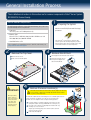
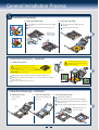
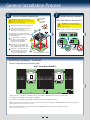
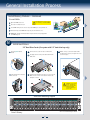
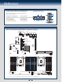
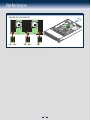
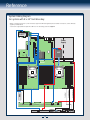
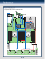
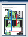
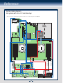
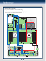
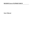
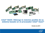
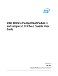
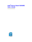
Intel® Server System R2000GZ/GL
Product Family
Quick Installation User's Guide
Thank you for buying an Intel® Server System. The following information will help you
assemble your Intel® Server System and install components.
If you are not familiar with ESD [Electrostatic Discharge] procedures used during
system integration, see the complete ESD procedures described in your Service Guide.
This guide and other supporting documents are located on the web at:
http://www.intel.com/support.
* 2.5" hard drive bay system as shown
G31061-004
(This page is intentionally left blank.)
Table of Contents
System Overview .............................................................................................................................. 1
General Installation Process ........................................................................................................ 2
Preparing the System ....................................................................................................... 2
Remove the Top Cover ..................................................................................................... 2
Remove the Air Duct ......................................................................................................... 2
Remove Processor Heatsink(s) ................................................................................... 2
Install the Processor(s) ................................................................................................... 3
Install Processor Heatsink(s) ........................................................................................ 4
Install Memory Modules ................................................................................................... 4
Install Hard Drives .............................................................................................................. 5
Install Optical Drive ............................................................................................................ 7
Install the Air Duct .............................................................................................................. 7
Remove Add-in Card Riser Assembly ....................................................................... 7
Install Add-in Card(s) ......................................................................................................... 7
Install Add-in Card Riser Assembly ........................................................................... 8
Install Rack Handles .......................................................................................................... 8
Install Intel® I/O Expansion Module (optional) ..................................................... 8
Install Intel® RAID C600 Upgrade Key (optional) ............................................... 8
Install Intel® RAID Smart Battery (optional) ......................................................... 8
Install Second Power Supply Module (optional) ................................................. 9
Install Bezel (optional) ...................................................................................................... 9
Install the Top Cover ......................................................................................................... 9
Finishing Up ............................................................................................................................ 9
Software ............................................................................................................................... 10
Reference ............................................................................................................................................ 11
i
Warning
Warning
Caution
Read all caution and safety
statements in this document
before performing any of the
instructions. Also see the Intel ®
Server Board and Server Chassis
Safety Information document at:
http://www.intel.com/support/
motherboards/server/sb/cs-010770
.htm for complete safety information.
Installation and service
of this product to be
performed only by
qualified service personnel
to avoid risk of injury from
electrical shock or energy
hazard.
Observe normal ESD
[Electrostatic Discharge]
procedures during system
integration to avoid possible
damage to server board and/or
other components.
Tools Required
Phillips*
screwdriver
Anti-static
wrist strap
Intel is a registered trademark of Intel Corporation or its subsidiaries in the United States and other countries. *Other names and brands may be claimed as the
property of others. Copyright © 2012, Intel Corporation. All rights reserved.
Thermal Operation and Configuration Requirements
To keep the system operating within supported maximum thermal limits, the system must meet the following operating and
configuration guidelines:
• Ambient inlet temperature cannot exceed 35º C and should not remain at this maximum level for long periods of time.
Doing so may affect long term reliability of the system.
• The CPU-1 processor + CPU heatsink must be installed first. The CPU-2 heatsink must be installed at all times,
with or without a processor installed.
• Memory Slot population requirements:
NOTE: Specified memory slots can be populated with a DIMM or supplied DIMM Blank. Memory population rules
apply when installing DIMMs.
– DIMM Population Rules on CPU-1
Install DIMMs in order; Channels A, B, C, and D. Start with 1st DIMM slot (blue) on each channel, then slot 2,
then slot 3 (24 DIMM board). Only remove DIMM blanks when populating the slot with a DIMM.
– DIMM Population on CPU-2
Install DIMMs in order; Channels E, F, G, and H. Start with 1st DIMM slot (blue) on each channel, then slot 2,
then slot 3 (24 DIMM board). Only remove DIMM blanks when populating the slot with a DIMM.
The following system configurations require the specific memory slots be populated at all times using a DIMM or supplied
DIMM blank:
– System Configuration: 24x 2.5" hard drive bay or 12x 3.5" hard drive bay configuration + 24 DIMM server
board Memory slots 2 and 3 populated on all memory channels.
– System Configuration: 16x 2.5" hard drive bay or 8x 3.5" hard drive bay configuration + 24 DIMM server board
Memory slot 3 populated on all memory channels.
– System Configuration: 24x 2.5" hard drive bay or 12x 3.5" hard drive bay configuration + 16 DIMM server board
Memory slot 2 populated on all memory channels.
• All hard drive bays must be populated. Hard drive carriers either can be populated with a hard drive or supplied
drive blank.
• The air duct must be installed at all times.
• In single power supply configurations, the second power supply bay must have the supplied filler blank installed at
all times.
• The system top-cover must be installed at all times. The only exception to this requirement is to hot replace a failed
system fan, in which case the top cover can be removed for no more than three minutes at a time.
ii
System Overview
Intel® Server System R2000GZ/GL Product Family
System Features and Components
Server Board
CPU1
CPU2
Add-in Card Riser Assembly
1+1 Redundant
Power Supply
Modules
System Fans
Hot Swap
Hard Drive Bays
Air Duct
Optical Drive Bay
Front Control Panel
* 2.5" Hard Drive Bay system as shown
Useful Information:
• Riser Slot 2 is not functional without having two processors installed.
• The SCU1 (4-7) port requires an Intel® RAID C600 Upgrade Key installed to be functional.
1
General Installation Process
The installation instructions in this section are for common components of Intel® Server System
R2000GZ/GL Product Family.
1
Minimum Hardware Requirements
To avoid integration difficulties and possible board damage, your system must
meet the following minimum requirements:
Preparing the System
Observe normal ESD (Electrostatic Discharge)
procedures.
• Processor:
Intel® Xeon® processor E5-2600 product family.
• Memory Type:
Minimum of one 512MB DDR3 1066/1333 MHz UDIMM or one 1GB
DDR3 800/1066/1333/1600 MHz RDIMM.
Place your Intel® Server System on a flat anti-static
surface to perform the following integration procedures.
Observe ESD procedures before reaching inside to make
server board connections or install components.
• Hard Disk Drives: SATA
For a complete list of compatible processors, heatsinks, and memory, see
http://www.intel.com/support.
2
3
Remove the Top Cover
A
B
Remove the Air Duct
Remove the four screws.
A
Carefully push in the two latches on the air duct.
Slide cover back and lift upward.
B
Rotate the back edge of the air
duct up to disengage the two
tabs from fan bulkhead.
B
A
A
B
B
4
IMPORTANT!
C
CAUTION: The heatsink has thermal interface material (TIM) on the underside
of it. Use caution so that you do not damage the thermal interface material.
Use gloves to avoid sharp edges.
A
3
The heatsink is attached to the server board/processor socket with captive fasteners.
Using a #2 Phillips* screwdriver, loosen the four screws located on the
heatsink corners in a diagonal manner using the following procedure:
A
B
C
Using a #2 Phillips* screwdriver, start with screw 1 and loosen it by
giving it two rotations and stop. (IMPORTANT: Do not fully loosen.)
Proceed to screw 2 and loosen it by giving it two rotations and stop.
Similarly, loosen screws 3 and 4.
Repeat steps A and B by giving each screw two rotations each time
until all screws are loosened.
Lift the heatsink straight up.
2
2
B
1
4
Pr
o
So ces
ck so
et r
Before proceeding
further, check your
Intel® Server System
for disconnected or
loose cables and
components that
may have occurred
during shipping.
Remove Processor Heatsink(s)
General Installation Process
5
Install the Processor(s)
A. Open the Socket Lever
A
B
B. Open the Load Plate
Push down the lever and slide away from the socket to
release it.
Repeat step A to release the lever on the other side.
A
Press the locking lever slightly to raise the
load plate.
B
Open the load plate all the way.
CL
OS
E
t
LG
NO
NN
1s
O
XC
FO
EN
U
11
OP
CP
0
A2
1s
ILM
t
O
56
EN
17
P
NO
2
1s
A
t
CP
NOTE: Release
the levers in the
order as shown.
U
A
B
B
NO
CP
U
Install the Processor(s) ... continued
A
C. Install the Processor
CAUTION: The underside of the processor has
components that may damage the socket pins
if installed improperly.
Components
Processor must align correctly with the socket opening before installation.
DO NOT DROP processor into socket!
A
B
C
CAUTION: When unpacking a processor,
hold by the edges only to avoid touching
the gold contact pins.
Save the
protective
cover.
Take the processor out of the box and remove the protective shipping cover.
B
Orient the processor with the socket so that the processor cutouts match the four orientation
posts on the socket.
Note location of gold key at corner of processor.
C
Install the Processor(s) ... continued
D. Remove the Cover
Press the cover to
remove it.
E. Close the Load Plate
Carefully lower the load plate over
the processor.
F. Latch the Locking Lever
A Push down the locking lever.
B Slide the tip of the lever under the notch in the load plate.
C
Save the
protective
cover.
Make sure the load plate tab engages under the socket lever
when fully closed.
Repeat the steps to latch the locking lever on the other side.
A
N
ON
XC
FO
11
20
A
LG
B
NOTE: Latch the levers in
the order as shown.
ILM
2
56
17
C
3
General Installation Process
6
CAUTION:
Do not
over-tighten
fasteners.
CAUTION: The heatsink has thermal interface
material (TIM) on the underside of it. Use caution so
that you do not damage the thermal interface material.
Use gloves to avoid sharp edges.
A
Remove the protective film on the TIM if present.
B
Align heatsink fins to the front and back of
the chassis for correct airflow.
Airflow goes from front-to-back of chassis.
B
Using a #2 Phillips* screwdriver,
start with screw 1 and engage screw
threads by giving it two rotations
and stop. (Do not fully tighten.)
W
LO
F
AIR
Each heatsink has four captive fasteners and
should be tightened in a diagonal manner using
the following procedure:
CAUTION: Observe normal ESD (ElectroStatic
Discharge) procedures to avoid possible damage to
system components.
DIMM notch and socket bump must align as shown below.
3
D
2
Install Memory Modules
DDR3 DIMM Memory Identification:
1
C
E
4
TIM
DDR3
Other
Memory
t
on
Fr
Repeat steps C and D by giving each
screw two rotations each time until
each screw is lightly tightened up to
a maximum of 8 inch-lbs torque.
sis
E
A
as
Proceed to screw 2 and engage screw
threads by giving it two rotations and
stop. Similarly, engage screws 3 and 4.
Ch
D
Pr
o
So ces
ck so
et r
C
7
Install Processor Heatsink(s)
NOTE: Heatsink styles may vary.
Install Memory Modules ... Continued
Memory Configurations and Population Order:
CPU1 Socket
DIMM_F3
DIMM_F2
DIMM_F1
DIMM_E3
DIMM_E2
DIMM_E1
DIMM_G1
DIMM_G2
DIMM_G3
DIMM_H1
DIMM_H2
DIMM_H3
DIMM_B3
DIMM_B2
DIMM_B1
DIMM_A3
DIMM_A2
DIMM_A1
DIMM_C1
DIMM_C2
DIMM_C3
DIMM_D1
DIMM_D2
DIMM_D3
Intel® Server Board S2600GZ
CPU2 Socket
For best performance, a minimum of four DIMMs per CPU is recommended, populated in the blue slot of each memory channel.
In a single-processor configuration, always populate A1 DIMM first.
In a dual-processor configuration, always populate A1 DIMM first for CPU1 and E1 DIMM first for CPU2.
NOTE: For additional memory configurations, see the Service Guide on the Intel® Server Deployment & Management DVD that accompanied your Intel®
Server System, or go to http://www.intel.com/support.
Memory sizing and configuration is supported only for qualified DIMMs approved by Intel. For a list of supported memory, go to:
http://serverconfigurator.intel.com.
4
General Installation Process
Install Memory Modules ... Continued
To Install DIMMs:
Open both DIMM socket levers.
C
Insert DIMM making sure the connector edge of the DIMM aligns correctly with the slot.
D
Push down firmly on the DIMM until it snaps into place and both levers close.
E
IMPORTANT! Visually check that each latch is fully closed and correctly engaged with
each DIMM edge slot.
C
E
CAUTION: Avoid touching contacts
when handling or installing DIMMs.
A
B
Note location of alignment notch.
8
D
B
A
Install Hard Drives
2.5" Hard Drive Carrier (For system with 2.5" hard drive bay only)
A
Press the green latch to
unlock.
C
Remove the four screws from the 2.5" HDD carrier.
D
Disengage and remove the plastic drive blank from the
HDD carrier.
A
D
F
With the lever open, insert the hard disk drive
assembly into the chassis, then push in the lever
to lock it into place.
F
C
B
E
Pull out the black lever and slide
the carrier out.
Install the hard disk drive using the four screws as shown.
Make sure the connector end of the drive matches the
backplane connector.
B
2.
DD
H
5"
E
CAUTION: If you don't install
all drives, empty drive bays
must be occupied by carriers
with plastic drive blank
provided to maintain proper
system cooling.
Hard Drive Numbering Diagram
0
1
2
3
4
5
6
7
8
9
10 11 12 13 14 15
16 17 18 19 20 21 22 23
24 x 2.5" hard drive bay as shown
Drive 0 Primary
5
General Installation Process
Install Hard Drives ... Continued
3.5" Hard Drive Carrier (For system with 3.5" hard drive bay only)
Remove the drive carrier by pressing the green button
and opening the lever.
B
Slide the carrier out.
C
Remove the four screws securing the
HDD interface bracket and remove the
HDD interface bracket.
TO
P
AB G
F T TIN E
OF OU IV
K M DR
EA RE RD
BR EFO HA
B 5´´
2.
A
AB NG
F T TI E
OF OU IV
K M DR
EA RE RD
BR EFO HA
B 5´´
2.
P
TO
C
B
A
D
Install the hard disk drive using the same
four screws as shown. Make sure the
connector end of the drive matches the
backplane connector.
D
E
With the lever open, insert the hard disk drive assembly into
the chassis.
F
Push in the lever to lock it into place.
3.
DD
´H
5´
CAUTION: If you don't install
all drives, empty drive bays
must be occupied by carriers
with plastic drive blank
provided to maintain proper
system cooling.
E
F
Install 2.5" Hard Drive as option:
d1 Break off the tab on the
d2 Install the HDD interface bracket
HDD interface bracket.
from top. Secure the bracket with
three screws as shown.
bracket to align the screw holes
with the right and left rail.
2.5"
P
TO
AB NG
F T TI E
OF OU IV
K M DR
EA RE RD
BR EFO HA
B 5´´
2.
d1
d3 Slide the 2.5" HDD into the
d4 Secure the hard disk drive using
the four screws for 2.5" HDD.
d4
HDD
2.5"
d3
Bo
Viewttom
HDD
d2
Hard Drive Numbering Diagram
1
3
5
7
0
2
4
6
8 x 3.5’’ hard drive bay as shown
2
5
8
11
1
4
7
10
0
3
6
9
Drive 0 Primary
12 x 3.5’’ hard drive bay as shown
6
General Installation Process
9
A
Install Optical Drive
Install the plastic guide onto the back
of the drive and attach with two screws
as shown.
B
Insert the optical drive into chassis opening
and push all the way until it stops.
C
Connect the cables as
shown.
cal
OptiDrive
A
IMPORTANT NOTE: If you do not
install a device at this location,
install the optical device bay filler
panel shown below. This is
required to maintain proper
system cooling.
C
er
Data
Pow
iew l
ar V ica
Re of Opt rive
D
al
tic e
Op vic bly
De em
s
As
B
10
A
B
C
Install the Air Duct
11
Lower front edge of the air duct to engage the two tabs
on the fan bulkhead.
Carefully push in the two latches on the air duct.
Remove Add-in Card
Riser Assembly
Grasp the riser assembly with both hands
and pull up to remove from system.
Push down the air duct into place.
Use care to avoid pinching system cables.
CAUTION:
Place the riser
assembly upside down
to avoid damage to the
riser card connector.
B
A
Riser Card
Connector
C
12
Install Add-in Card(s)
A
C
• Full-height PCIe Card Shown
NOTE: Add-in card install sequence for low-profile add-in
cards is the same.
A
B
C
Remove the filler panel from the add-in card slot and
remove the screw as shown.
Insert add-in card until it seats in the riser connector.
A
rd
in Ca
Add-
B
Secure add-in card with screw as shown.
Riser Connector
NOTE: Make sure that all empty add-in card slots have
filler panels installed.
CAUTION:
Observe normal ESD precautions
when installing add-in cards.
7
REM
OVE
Fille
r Pa
nel
General Installation Process
13
Install Add-in Card Riser Assembly
A
B
C
D
E
Hooks (2)
Slide back the card guide on the air duct.
Pull up the blue plastic pin out of the card guide.
B
Slots (2)
Position the riser card edge connector over the server board
riser socket and align the two hooks on the back edge of the
riser assembly with the slots on the back of the chassis, then
press straight down into riser socket.
Slide forward the card guide to lock in the back edge of the
add-in card.
Insert the blue plastic pin into the card guide to secure the
add-in card.
E
Car
d
NOTE: Rack handles are required to install the
bezel. For detailed instructions, see the product
Service Guide available on the Intel® Server
Deployment & Management DVD.
15
-in
Add
NOTE:
- Step A, B, D, and E are only needed when a full-length PCI card
is installed on the riser assembly.
- Riser Slot 2 is not functional without having two processors installed.
14 Install Rack Handles
C
A
D
Install Intel® I/O Expansion Module
(optional)
A
Squeeze the sides of the I/O module
bay filler plate, and pull it away from
the chassis back panel.
B
Fit the front of the module into the
back panel slot and align the I/O
Module over the three stand-offs.
C
Carefully press down the I/O
module to engage connectors.
D
Secure the module with the three
screws as shown.
NOTE: If included, remember to
install the EMI shield.
16 Install Intel® RAID C600 17
Upgrade Key (optional)
Locate the white 4-pin key header next to Riser Slot 1.
Carefully pickup the Intel® RAID C600 Upgrade Key.
Match the Key and connector orientation and press
down to install.
A
B
EY
G_K
STO
P
R_U
D
I/O
e
dul
Mo
B
A
C
I/O Connector
Install Intel® RAID Smart Battery (optional)
Locate the mounting holes
inside the chassis and
reposition all cables routed
over the fan bulkhead.
Position the battery against
the side wall and through the
opening in the fan bulkhead.
Align the tabs on the plastic
battery holder with the
mounting holes in the
chassis and slide the plastic
battery holder toward the
front of the system until
the tabs engage with the
mounting holes.
8
Fan Bulkhead
B
A
General Installation Process
18
A
Install Second Power Supply Module (optional)
Use the 'finger hole' to remove the
filler panel.
B
Insert the power supply module into the power
supply cage and push all the way until it clicks
into place.
Power Supply Removal:
Pull out the module from the chassis by holding
the handle and pressing the green latch in the
direction shown.
A
B
Finger Hole
19
20
Install Bezel (optional)
NOTE: Before installing the bezel, you must install the rack handles.
A
Lock the right end of the front bezel to the rack handle.
B
Push in the left side of the bezel until it clicks into place.
Lock the bezel if needed.
B
Install the Top Cover
A
Place the top cover on system and slide towards the
front of the chassis until the recessed front edge is fully
engaged.
B
Install the three screws at the front and torque to
7-9in-lbs. Then install the screw at the back and
torque to 7-9in-lbs.
Recessed
Edge
A
B
A
A
21
Finishing Up
Before installing your operating system, you must finish your system
installation, make I/O connections, and plug in power cord(s).
Serial Port B (optional)
Add-in Card Slots
1. Verify the system top cover is installed.
2. Install the server into the rack using the instructions provided with the rack
mounting kit.
3. Connect your USB keyboard/mouse, video and other I/O cables/devices
as shown.
Then connect the power cord(s).
1st Power
Supply
Module
CAUTION: This system must be operated with the TOP COVER installed to
ensure proper cooling.
2 nd Power
Supply
Module
NIC 1 NIC 3
Network
9
Serial
Intel ® RMM4 Intel ® I/O
NIC Port
Module
Port A
(optional)
Video
USB
Ports
NIC 2 NIC 4
General Installation Process
22
Software • BIOS, Drivers, and Operating System Installation
A. Update the System Software:
Update the System BIOS, ME Firmware, BMC Firmware, and FRU & SDR data, using the latest versions posted for this product at
http://www.intel.com/support.
NOTE: The FRUSDR utility must be run for full platform management functionality.
B. Configure your RAID Controller:
If using a RAID card, use the instructions provided with the RAID controller. If using on-board RAID, you must activate RAID in the BIOS setup. See the Intel® Server System
R2000GZ/GL Service Guide for more information.
C. Install your Operating System:
Use the instructions provided with the RAID controller and with the operating system.
D. Install Operating System Drivers:
With the operating system running, insert the Intel® Server Deployment & Management DVD. If using a Microsoft Windows* operating system, the Express Installer will
autorun and allow you to select the appropriate drivers to install. On other operating systems, browse the DVD folders to locate and install the driver files.
E. Install Intel® System Management Software (optional):
Download the latest version of the Intel® System Management Software from http://www.intel.com/go/servermanagement and use the instructions provided at that link to
install the software.
* Other brands and names may be claimed as the property of others.
10
Reference
Front Panel Controls and Indicators
Standard Control Panel
Your system may include one of two front control panel types.The
features of each are as follows:
A. ID Button with integrated LED
B. NMI Button (recessed, tool required)
C. LAN-1 Activity LED
D. LAN-3 Activity LED
E. System Cold Reset Button
J I
F. System Status LED
G. Power Button with integrated LED
H. HDD Activity LED
I. LAN-4 Activity LED
J. LAN-2 Activity LED
A
H
B C D E
F
G
H
A
F
G
I
C
DB
Intel® Server Board S2600GZ/GL Component Layout
Status
LED Diagnostic
LEDs
ID LED
Serial A
Video
NIC4 NIC3 NIC2 NIC1
USB
Riser Slot 1
eUSB SSD
RMM4 Lite
RMM4
NIC
TPM Connector
Internal USB
Storage Upgrade Key
SCU0 (0-3)
SCU1 (4-7)
I/O Expansion
Module
Connector
Serial B
SAS Module
Connector
HSBP I2C
SATA 0
SATA 1
Riser Slot 2
Main Power 2
DIMM_G1
DIMM_G2
DIMM_G3*
DIMM_H1
DIMM_H2
DIMM_H3*
CPU 1 Socket
System
Fan 1
System
Fan 2
HSBP
Power
Connector
Optional
12V Power 2
DIMM_B3*
DIMM_B2
DIMM_B1
DIMM_A3*
DIMM_A2
DIMM_A1
DIMM_C1
DIMM_C2
DIMM_C3*
DIMM_D1
DIMM_D2
DIMM_D3*
Optional
12V Power 1
Main Power 1
DIMM_F3*
DIMM_F2
DIMM_F1
DIMM_E3*
DIMM_E2
DIMM_E1
IPMB
HDD LED
CPU 2 Socket
Front Panel USB
Front Panel Video
System
System Fan 6
Fan 3
Chassis Intrusion System Fan 5
System
Front Panel
Fan 4 LCP
ODD/SSD Power Connector
* - For server systems integrated with Intel® Server Board S2600GZ only.
See your Intel® Server System R2000GZ/GL Service Guide for expanded component and connection information.
11
E
J
Reference
System Fan Connection
Air F
1
FAN 1 FAN 2
FAN 3 FAN 4
FAN 5
A complete list of accessories and spares can be found at http://www.intel.com/support.
12
2
3
4
5
low
Reference
System Cabling Diagram
For system with 8 x 3.5” hard drive bay:
NOTES: To activate the port SCU1 (4-7) on the server board, a proper Intel® RAID C600 Upgrade Key must be installed. For instructions, see Intel® RAID C600
Upgrade Key Installation Guide.
A second SSD is supported when the optical drive is NOT in use. For cable routing, please refer to Page 14.
Intel® Integrated
RAID Module
Power
Supply
SSD
2
8 x 3.5" HSBP
Optical Drive
13
Front Panel USB
Front Panel Video
BBU
Front Panel
Server
Board
Mount on Air Duct
IC
Reference
System Cabling Diagram
For system with 12 x 3.5” hard drive bay:
0 1
2
3 4
5
Installed into PCIe Riser Card
Intel® Integrated
RAID Module
Intel® RAID
Expander Card
RES2SV240
Power
Supply
SSD
SSD
2
Mount on Air Duct
IC
BBU
Front Panel
Server
Board
Interposer
Board
12 x 3.5" HSBP
14
Reference
System Cabling Diagram
For system with 8 x 2.5” hard drive bay:
NOTES: To activate the port SCU1 (4-7) on the server board, a proper Intel® RAID C600 Upgrade Key must be
installed. For instructions, see Intel® RAID C600 Upgrade Key Installation Guide.
A second SSD is supported when the optical drive is NOT in use. For cable routing, please refer to Page 17.
Intel® Integrated
RAID Module
Power
Supply
SSD
2
Front Panel USB
BBU
Front Panel
Server
Board
Front Panel Video
Mount on Air Duct
IC
8 x 2.5" HSBP
Optical Drive
15
Reference
System Cabling Diagram
For system with 16 x 2.5” hard drive bay:
NOTE: A second SSD is supported when the optical drive is NOT in use. For cable routing, please refer to Page 17.
Intel® Integrated
RAID Module
Power
Supply
SSD
2
SAS
Expander
B
C
D
8 x 2.5" HSBP
E
Front Panel USB
A
Front Panel
BBU
Server
Board
Front Panel Video
Mount on Air Duct
IC
F
8 x 2.5" HSBP
Optical Drive
2
IC
16
Reference
System Cabling Diagram
For system with 24 x 2.5” hard drive bay:
NOTE: To activate the port SCU1 (4-7) on the server board, a proper Intel® RAID C600 Upgrade Key must be
installed. For instructions, see Intel® RAID C600 Upgrade Key Installation Guide.
Intel® Integrated
RAID Module
Power
Supply
SSD
SSD
2
Mount on Air Duct
IC
A
SAS
Expander
B
G
H
C
D
8 x 2.5" HSBP
Front Panel
BBU
Server
Board
I
E
F
Interposer
Board
8 x 2.5" HSBP
2
8 x 2.5" HSBP
2
IC
IC
17
G31061-004