1
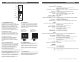
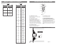
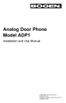
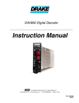
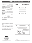
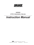
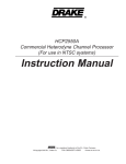
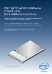
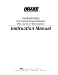
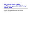
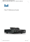
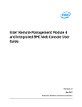
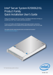
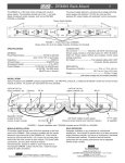
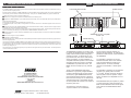
8
WARRANTY AND SPECIFICATIONS
®
VMM860AG VIDEO MODULATOR
1
THREE YEAR LIMITED WARRANTY
R.L. DRAKE COMPANY warrants to the original purchaser this product shall be free from defects in material or workmanship for three (3)
years from the date of original purchase.
12 POSITION RACK MOUNT
POWER SUPPLY
During the warranty period the R.L. DRAKE COMPANY or an authorized Drake service facility will provide, free of charge, both parts and
labor necessary to correct defects in material and workmanship. At its option, R.L. DRAKE COMPANY may replace a defective unit.
To obtain such warranty service, the original purchaser must:
(1) Retain invoice or original proof of purchase to establish the start of the warranty period.
(2) Notify the R.L. DRAKE COMPANY or the nearest authorized service facility, as soon as possible after discovery of a possible defect,
of:
(a) the model and serial number,
(b) the identity of the seller and the approximate date of purchase; and
(c) A detailed description of the problem, including details on the electrical connection to associated equipment and the list of such
equipment.
POWER SUPPLY
MODULATOR
MODULATOR
MODULATOR
MODULATOR
MODULATOR
MODULATOR
MODULATOR
MODULATOR
MODULATOR
MODULATOR
AUDIO
AUDIO
AUDIO
AUDIO
AUDIO
AUDIO
AUDIO
AUDIO
AUDIO
VIDEO
VIDEO
VIDEO
VIDEO
VIDEO
VIDEO
VIDEO
VIDEO
VMM806AG
VIDEO
PWR
PWR
PWR
PWR
PWR
PWR
PWR
PWR
PWR ERROR
AUDIO
MODULATOR
AUDIO
AUDIO
VIDEO
VIDEO
POWER
A/V
A/V
A/V
A/V
A/V
A/V
A/V
A/V
A/V
PWR
PWR
A/V
VIDEO
A/V
#
#
#
#
#
#
#
#
#
#
#
CH
CH
CH
CH
CH
CH
CH
CH
CH
CH
CH
RF
RF
RF
RF
RF
RF
RF
RF
2
5
RF
RF
RF
CATV
BC
TV
CATV
+100
(3) Deliver the product to the R.L. DRAKE COMPANY or the nearest authorized service facility, or ship the same in its original container
or equivalent, fully insured and shipping charges prepaid.
A /V
RF
Correct maintenance, repair, and use are necessary to obtain proper performance from this product. Therefore carefully read the Instruction
Manual. This warranty does not apply to any defect that R.L. DRAKE COMPANY determines is due to:
(1) Improper maintenance or repair, including the installation of parts or accessories that do not conform to the quality and specifications
of the original parts.
(2) Misuse, abuse, neglect or improper installation.
OR
4 POSITION
RACK MOUNT
VMM860AG and other compatible
modular units
(3) Accidental or intentional damage.
RF
BC
TV
5
A/V
CATV
+100
VIDEO
AUDIO
CATV
2
POWER
ERROR
VMM806AG
RF
5
A/V
BC
TV
CATV
+100
VIDEO
AUDIO
CATV
2
POWER
ERROR
BC
TV
VMM806AG
RF
5
A/V
CATV
+100
VIDEO
AUDIO
CATV
2
POWER
ERROR
RF
5
A/V
BC
TV
CATV
+100
VIDEO
AUDIO
CATV
2
POWER
ERROR
VMM806AG
The foregoing constitutes R.L. DRAKE COMPANY’S entire obligation with respect to this product, and the original purchaser shall have no
other remedy and no claim for incidental or consequential damages, losses or expenses. Some states do not allow limitations on how long
an implied warranty lasts or do not allow the exclusions or limitation of incidental or consequential damages, so the above limitation and
exclusion may not apply to you.
VMM806AG
POWER SUPPLY
All implied warranties, if any, including warranties of merchantability and fitness for a particular purpose, terminate three (3) years from the
date of the original purchase.
This warranty gives you specific legal rights and you may also have other rights which vary from state to state. This warranty shall be
construed under the laws of Ohio.
®
R.L. DRAKE COMPANY
230 INDUSTRIAL DRIVE
FRANKLIN, OHIO 45005 U.S.A.
CUSTOMER SERVICE AND PARTS TELEPHONE:
+1 (937) 746-6990
TELEFAX:
+1 (937) 806-1576
WORLD WIDE WEB SITE: http://www.rldrake.com
The VMM860AG modulator is a member of the
R.L. Drake 19" Mini-Rack Series, a professional
quality modular headend system designed to
optimize rack space. An assortment of up to
(12) modular units, such as the fixed channel
series of modulators, or agile modulators, or
compatible audio/video products can be racked
alongside a single power supply in the Drake
model RMM12, 12 position rack mount. The
RMM4 rack mount accepts up to (4) modular
units.
ensures optimum vestigial selectivity for
adjacent channel headends. An optional FCC
predistortion SAW response is also available for
the VMM860AG.
The R.L. Drake VMM860AG Audio-Video
Modulator is a high quality, vestigial sideband
unit with synthesized visual and aural carriers.
The frequency agile VMM860AG allows front
panel pushwheel switch selection of standard
CATV channels 2 through 135, or VHF/UHF TV
channels 2 through 69. Aeronautical channels
are offset positive with a tolerance of ±5 kHz as
required by FCC rules.
The modulator is designed to accept standard
(negative sync) polarity video at nominal
1 V p-p level. All level controls are located on
the front panel for ease of operation. Output
level is +45 dBmV and is adjustable over a 10
dB range.
The heterodyne conversion system, in
conjunction with the use of a SAW filter,
® is a registered trademark of the R.L. Drake Company
© Copyright 2004 R.L. Drake Company
P/N: 3852469A-10-2004
The modulator is designed to accept any
standard audio/video source such as NTSC
video and audio baseband signals from a
satellite receiver, TV camera, videotape
recorder, TV demodulator, or similar signal
source.
Field-defeatable audio pre-emphasis, by means
of a rear panel switch, allows transmission of
BTSC encoded baseband stereo audio signals
when used with the Drake MMTS20 stereo
encoder.
2
FRONT PANEL CONTROLS and INDICATORS
F1
SPECIFICATIONS
RF
Frequency Range: 54 to 864 MHz;
Standard, HRC, or IRC CATV channels 2 to 135,
Broadcast TV channels 2 to 69.
FCC Frequency Offsets: Automatic (+12.5 kHz, +25 kHz, or none as required for each
channel).
Output level: +45 dBmV minimum (10 dB adjustment range).
Output Impedance: 75 Ohms, 8 dB return loss.
A/V Ratio: Audio carrier level, adjustable from -22 to -12 dB
referenced to video carrier level.
Frequency Stability: Within ±5 kHz
Intercarrier Frequency: 4.5 MHz
Spurious Outputs (5 MHz to 1 GHz): -60 dBc, measured at -15 dB A/V ratio and with modulator
output level of +45 dBmV.
In-channel C/N: 65 dB typical, 4 MHz bandwidth.
Broadband Noise: -78 dBc typicial, 4 MHz bandwidth @ +45 dBmV output.
VMM860AG
POWER/
ERROR
F2
AUDIO
F3
VIDEO
F4
F5
2
5
C AT V
CATV
+100
BC
TV
A/V
F6
RF
F7
Figure 1
F1 - POWER/ERROR Indicator
Lights when the unit is connected to the
required source of DC power via the rear panel
DC INPUT connector. A flashing condition
indicates an invalid channel setting or other
conditions that would cause the unit to operate
on an invalid channel. The RF output is
switched off for flashing (ERROR) conditions.
F2 - AUDIO Level Control
The setting of this screwdriver adjustment
determines the aural carrier deviation. Clockwise rotation increases the carrier deviation.
F3 - VIDEO Level Control
The setting of this screwdriver adjustment
determines the video modulation level.
Clockwise rotation increases the modulation
depth.
F4 - Channel Number Switch
Sets the desired operating channel for standard
CATV channels 02 through 135 or Broadcast
TV channels 02 through 69. See also Item F5
which sets the type of channel (CATV or
Broadcast TV) and sets the leading “1” for
CATV channels 100 through 135.
CAUTION: USE AN INSULATED SCREWDRIVER
BLADE WHEN ADJUSTING THE AUDIO, VIDEO,
A/V, OR RF ADJUSTMENTS.
THIS WILL PREVENT THE POSSIBILITY OF
SHORTING CIRCUITRY TO THE FRONT PANEL
IN THE EVENT THAT THE SCREWDRIVER
SLIPS OUT OF THE SLOT IN THE PLASTIC
SHAFT OF THE POTENTIOMETER.
F5 - Mode Switch
Sets the type of channel, CATV or Broadcast
TV (“BC TV”). The first position of the switch
(“+100”) sets a leading “1” for CATV channels
100 through 135. See also Item F4 for setting
the channel number.
For example:
Setting for CATV
channel "125"-
2
For example:
Setting for CATV
channel "25"-
2
5
CATV
CATV
+100
7
5
CATV
BC
TV
CATV
+100
BC
TV
F6 - A/V Ratio Control
This screwdriver adjustment varies the level of
the aural carrier over a range from 12 to
22 dB below the visual carrier. The aural carrier
should be adjusted to approximately 15 dB
below the visual carrier (normal operation).
Clockwise rotation increases the aural carrier
level.
VIDEO
Input Level for 87.5% Modulation: 0.65 Vp-p to 1.5 Vp-p. Manual gain adjust with
front panel control.
Input Impedance: 75 Ohms, return loss of 26 dB minimum.
Frequency Response: 20 Hz to 4.2 MHz, ±1 dB.
C/L Delay: Within 50 nSec. of 0 nSec. (standard), or
FCC predistortion, (option).
Differential Gain: 3% maximum (10 to 90% APL).
Differential Phase: 30 maximum (10 to 90% APL).
AUDIO
Input Level for 25 kHz Peak Deviation: 125 mV rms to 2.5 V rms. Manual gain adjust with
front panel control.
Input Impedance: Greater than 10 K Ohms, unbalanced.
Pre-emphasis: 75 µSec. normal, defeatable (flat) by rear panel switch for
BTSC baseband stereo compatibility.
Frequency Response: 40 Hz to 15 kHz, ±1.0 dB referenced to 75 µSec.
pre-emphasis curve.
40 Hz to 100 kHz, ±0.5 dB if pre-emphasis is defeated.
S/N ratio: 65dB.
Total Harmonic Distortion: 1% maximum.
GENERAL
DC Power Input: +12 V ±5% at 200 mA
+5 V ±5% at 350 mA
Operating Temperature: 00 C to +500 C ambient.
Size: 1” W x 3.5” H x 7.5” D. (2.5 cm) W x (8.9 cm) H x (19.1 cm) D.
Weight: 10.7 oz. (0.3 Kg).
F7 - RF Output Level
This screwdriver adjustment permits decreasing
the RF output level a minimum of 10 dB as the
control is rotated counterclockwise. Set the
control for a +45 dBmV output level .
Specifications subject to change without notice or obligation.
6
REAR PANEL CONNECTIONS / INTERNAL JUMPERS
BROADCAST TV CHANNEL OUTPUT FREQUENCIES
CATV
TABLE 2: BC TV
CATV
+100
CATV
BC
TV
VHF BROADCAST CHANNELS
Channel Number
3
Visual Carrier
Frequency (MHz)
CATV
+100
BC
TV
R1
UHF BROADCAST CHANNELS
Channel Number
Visual Carrier
Frequency (MHz)
R2
R5
VIDEO INPUT
FLAT
NORM
2
3
4
5
6
7
8
9
10
11
12
13
55.25
61.25
67.25
77.25
83.25
175.25
181.25
187.25
193.25
199.25
205.25
211.25
14
15
16
17
18
19
20
21
22
23
24
25
26
27
28
29
30
31
32
33
34
35
36
37
38
39
40
41
42
43
44
45
46
47
48
49
50
51
52
53
54
55
56
57
58
59
60
61
62
63
64
65
66
67
68
69
471.25
477.25
483.24
489.25
495.25
501.25
507.25
513.25
519.25
525.25
531.25
537.25
543.25
549.25
555.25
561.25
567.25
573.25
579.25
585.25
591.25
597.25
603.25
609.25
615.25
621.25
627.25
633.25
639.25
645.25
651.25
657.25
663.25
669.25
675.25
681.25
687.25
693.25
699.25
705.25
711.25
717.25
723.25
729.25
735.25
741.25
747.25
753.25
759.25
765.25
771.25
777.25
783.25
789.25
795.25
801.25
AUDIO INPUT
R3
+5V
+12V
GND
DC INPUT
R4
RF OUT
Figure 2
R4 - RF OUTPUT Connector
This is the modulator output.
R1 - VIDEO INPUT Connector
This is the nominal 1 Vp-p baseband video
input to the modulator.
R5 - AUDIO PRE-EMPHASIS SWITCH
This switch allows selection of either normal
audio pre-emphasis or flat audio response. For
normal mono audio, input to the modulator via
R2, set switch to NORM position. If the
MMTS20 BTSC stereo encoder is used, set this
switch to FLAT and connect stereo audio to the
MMTS20. The encoder will in turn connect to
R2.
R2 - AUDIO INPUT Connector
This is an unbalanced audio input to the
modulator circuits. This “RCA” (phono)
connector input accepts mono audio from 125
mVrms to 2.5 Vrms levels. If the MMTS20
stereo encoder is used, this input accepts the
composite BTSC stereo output of the MMTS20.
R3 - DC INPUT Connector
This 3-pin connector (Male) accepts the
appropriate mating DC power cable.
INTERNAL JUMPER SETTING: STD, HRC, IRC
STD
HRC
IRC
Figure 3
4
CATV CHANNEL OUTPUT FREQUENCIES
INSTALLATION
CATV
CONNECTIONS AND CONTROLS
All connections to and from each modulator are
made through the rear panel. Figure 4
illustrates an installation with (12) modulator
units combined through a passive signal
combiner. Additional channels can be added by
using additional fixed channel or agile type
modulators and either multi-port combiners or
combinations of two-port combiners.
INSTALLATION NOTES
Level adjustment provides optimum
performance in multi-channel installations.
The modulator outputs should be checked
periodically with a spectrum analyzer to
maintain a ±1 dB variation of adjacent channel
carriers. Aural/Visual (A/V) ratios should be
held to -15 dB or less. The output ‘RF’ and ‘A/V
(Ratio)’ controls are used respectively to make
these adjustments.
RACK MOUNTING
Adequate ventilation is very important in
multi-channel installations. The RMM12 or
RMM4 cages should be spaced apart vertically
by at least one rack unit (1.75") height wherever
possible. Some air movement is mandatory in
enclosed rack cabinets. Excessive heat will
shorten component life and modulator performance will be degraded without proper cooling.
AUDIO INPUTS
AC POWER
CORD
VIDEO INPUTS
MODULATOR UNITS
(Fixed channel and/or Agile types)
DC POWER
CABLE
RF COMBINER
SYSTEM OUT
Figure 4
POWER SUPPLY REQUIREMENT
This VMM860AG agile modulator requires more
current than the fixed channel units. Therefore,
new 12 position rack installations with multiple
VMM860AG modulators (up to 12) must use the
Drake PSM121 (or equivalent) high capacity
power supply module.
The power supply in the four position rack
system can power up to four VMM860AG
modulators or any mix of fixed and agile VMM
models up to four total modulators.
FREQUENCY CHART
The chart on the following page shows the
standard CATV channel coverage of the
VMM860AG. Where an offset is indicated, this
amount of positive frequency offset is added to
the frequency indicated in the middle column.
As shown, this occurs only on channels
required to be offset by the FCC.
HRC or IRC frequencies can be set by means
of an internal jumper. See Figure 3. No jumper
will result in the STD channel plan selection.
TABLE 1: CATV
Output Channel
Switch Setting
02
03
04
05
06
07
08
09
10
11
12
13
14
15
16
17
18
19
20
21
22
23
24
25
26
27
28
29
30
31
32
33
34
35
36
37
38
39
40
41
42
43
44
45
46
47
48
49
50
51
52
53
54
55
56
57
58
59
60
61
62
63
64
65
66
67
68
69
CATV
+100
CATV
BC
TV
CATV
+100
Visual Carrier
Frequency
Frequency (MHz) Offset (kHz)
55.25
61.25
67.25
77.25
83.25
175.25
181.25
187.25
193.25
199.25
205.25
211.25
121.25
127.25
133.25
139.25
145.25
151.25
157.25
163.25
169.25
217.25
223.25
229.25
235.25
241.25
247.25
253.25
259.25
265.25
271.25
277.25
283.25
289.25
295.25
301.25
307.25
313.25
319.25
325.25
331.25
337.25
343.25
349.25
355.25
361.25
367.25
373.25
379.25
385.25
391.25
397.25
403.25
409.25
415.25
421.25
427.25
433.25
439.25
445.25
451.25
457.25
463.25
469.25
475.25
481.25
487.25
493.25
5
NONE
NONE
NONE
NONE
NONE
NONE
NONE
NONE
NONE
NONE
NONE
NONE
±12.5
±12.5
±12.5
NONE
NONE
NONE
NONE
NONE
NONE
NONE
+12.5
+12.5
+12.5
+12.5
+12.5
+12.5
+12.5
+12.5
+12.5
+12.5
+12.5
+12.5
+12.5
+12.5
+12.5
+12.5
+12.5
+12.5
+25
+12.5
+12.5
+12.5
+12.5
+12.5
+12.5
+12.5
+12.5
+12.5
+12.5
+12.5
NONE
NONE
NONE
NONE
NONE
NONE
NONE
NONE
NONE
NONE
NONE
NONE
NONE
NONE
NONE
NONE
BC
TV
Output Channel
Switch Setting
Visual Carrier
Frequency (MHz)
Frequency
Offset (kHz)
70
71
72
73
74
75
76
77
78
79
80
81
82
83
84
85
86
87
88
89
90
91
92
93
94
95
96
97
98
99
499.25
505.25
511.25
517.25
523.25
529.25
535.25
541.25
547.25
553.25
559.25
565.25
571.25
577.25
583.25
589.25
595.25
601.25
607.25
613.25
619.25
625.25
631.25
637.25
643.25
91.25
97.25
103.25
109.25
115.25
NONE
NONE
NONE
NONE
NONE
NONE
NONE
NONE
NONE
NONE
NONE
NONE
NONE
NONE
NONE
NONE
NONE
NONE
NONE
NONE
NONE
NONE
NONE
NONE
NONE
NONE
NONE
NONE
+25
+25
CATV
CATV +100
100
101
102
103
104
105
106
107
108
109
110
111
112
113
114
115
116
117
118
119
120
121
122
123
124
125
126
127
128
129
130
131
132
133
134
135
649.25
655.25
661.25
667.25
673.25
679.25
685.25
691.25
697.25
703.25
709.25
715.25
721.25
727.25
733.25
739.25
745.25
751.25
757.25
763.25
769.25
775.25
781.25
787.25
793.25
799.25
805.25
811.25
817.25
823.25
829.25
835.25
841.25
847.25
853.25
859.25
CATV
+100
BC
TV
NONE
NONE
NONE
NONE
NONE
NONE
NONE
NONE
NONE
NONE
NONE
NONE
NONE
NONE
NONE
NONE
NONE
NONE
NONE
NONE
NONE
NONE
NONE
NONE
NONE
NONE
NONE
NONE
NONE
NONE
NONE
NONE
NONE
NONE
NONE
NONE