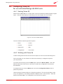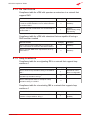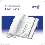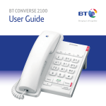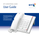
1
InterChange
iQ 2000 and iQ 2000plus
User Guide
Acknowledgements
Information in this document is subject to change without notice and does not represent a
commitment on the part of Westell Limited. The software may be used or copied only in
accordance with the terms of the purchase agreement. It is against the law to copy the software
on any medium except as specifically allowed in the purchase agreement. No part of this manual
may be reproduced or transmitted in any form or by any means, electronic or mechanical, including
photocopying or recording, for any purpose without the permission of Westell Limited.
Trademarks
Westell Limited recognises all third party trademarks.
Change History
Issue
Product
Status
Date
010
020
030
040
050
060
070
Wes IiQ 2000 User Guide
Wes IiQ 2000 User Guide
Wes IiQ 2000 User Guide
Wes IiQ 2000 User Guide
Wes IiQ 2000 User Guide
IiQ 2000plus User Guide
IiQ 2000plus User Guide
First Issue
Phase 2
Frozen
Restyle
Update
Revised
Revised
Dec 2000
Apr 2001
Mar 2002
Jan 2003
Jun 2003
Nov 2004
Westell limited
Ringway House
Bell Road
Daneshill
Basingstoke
Hampshire, RG24 8FB
United Kingdom
Tel: +44 (0) 1256 843311
Fax: +44 (0) 1256 840429
email: [email protected]
www.westell.co.uk
© Copyright 2003, 2004 Westell limited
All rights reserved
Document number: UM 380 03 010
User Guide
Contents
Acknowledgements
2
Preface
1
1 Introduction
3
Trademarks
Change History
Scope of this Guide
Management
Vision iQ
1.1
1.2
1.3
1.4
InterChange iQ 2000
InterChange iQ 2000plus
Management with Vision iQ
Environment
1.4.1 External Dimensions and Weight
1.4.2 Power Requirement
1.5 Approvals and Safety
2 Hardware Installation Procedure
2.1 Introduction to Unit Installation
2.2 Unit Installation
2.2.1 Unpacking and Inspection
2.2.2 Hardware Installation
Back Panel Equipment
2.3 Power-On and Self-Test
2.3.1 Terminal Connections
2.3.2 Self-Test
2
2
1
1
2
3
4
4
5
5
5
5
6
6
6
6
7
7
9
9
9
2.4 Vision iQ Management Software Installation
2.5 InterChange iQ 2000 and 2000plus Installation
10
10
2.6 Cabling into a Management System
14
2.7 Network Cabling
15
2.5.1
2.5.2
2.5.3
2.5.4
2.5.5
2.6.1
2.6.2
2.6.3
2.6.4
Set Factory Default Values
Set Time and Date
Protocol Configuration
Configuration using the Quick Start wizard
Configuration changes (for manual changes to the default settings)
Alarm Signal Cabling
Alarm Signal Cable Test
Management Terminal Cabling
Management Terminal Cable Connection Test
2.7.1 Port Usage
2.7.2 Cabling Practice
2.7.3 Cabling Procedure
UM380 03 010
11
11
12
13
13
14
14
14
14
15
15
15
iii
InterChange iQ 2000 and iQ 2000plus
3 Switches and LEDs
3.1 Switches
3.1.1 Power ON/OFF switch
3.1.2 Sync switch
3.1.3 Port Impedance switches
3.2 Front Panel LEDs
3.2.1
3.2.2
3.2.3
3.2.4
Status LEDs
LAN LEDs
Port LEDs
Power LED
4 Management using Vision iQ
4.1
4.2
4.3
4.4
Configuration
Upgrade Configuration Procedure
Software Components
PC to InterChange Connection
4.4.1 Serial Link
4.4.2 Ethernet Connection
4.4.3 PC Specification
17
17
17
17
17
17
18
18
18
19
19
19
19
19
19
20
20
4.5 Software Installation
4.6 Configuring Vision iQ for use with InterChange iQ 2000 units
20
21
4.7 Connect
23
4.8 Diagnostics
29
4.9 Major Alarms
4.10 Port Errors
4.11 Call Statistics
4.12 Loopback
4.13 Using the Configuration Wizard
4.14 InterChange iQ 2000plus Enhancements
31
32
33
34
34
43
4.6.1 Starting Vision iQ
4.6.2 Working with Vision iQ
4.6.3 Vision iQ Mode Options
4.7.1
4.7.2
4.7.3
4.7.4
4.7.5
4.7.6
4.7.7
4.7.8
Connection
Disconnect
Reconnect
Shelf Definitions
Shelf Properties Group
Shelf Definitions Present Group
Define Poll List
Global Poll
4.8.1
4.8.2
4.8.3
4.8.4
4.14.1
4.14.2
4.14.3
4.14.4
4.14.5
iv
17
Diagnostics Overview
System Page
Module Page
Hardware Page
Proxy Diversion
Redirection Timeout
Q.932 Redirecting Number Information
CCM Message Waiting Indication
Configuration Wizard Variation
21
21
22
23
24
24
24
25
25
27
28
29
30
30
31
43
43
44
44
44
UM380 03 010
User Guide
5 Conversions and Transparency
5.1 Q.931/DPNSS Conversion
5.1.1 Default Configuration
5.1.2 Configuration Options
45
45
45
45
5.2 Transparent Signalling
47
5.3 Interworking Between DPNSS & QSIG Equipment
5.4 IiQ 2000plus Proxy Interworking Between DPNSS & Q.931
5.5 Interworking DPNSS with Cisco Call Manager
48
49
50
5.2.1 Overview
5.2.2 Supported Services
6 Manual Configuration or Upgrade of Software
Protocol Options
6.1 General Module Configuration Procedure
6.1.1 The Configuration Menu System
6.1.2 Menu Help Facilities
6.1.3 Confirming Configuration Changes
47
47
52
52
52
52
52
6.2 Manual Configuration and Upgrade Options
53
6.3 Q.931/DPNSS Conversion Configuration
54
6.4 DPNSS/QSIG Transparency Options Configuration
57
6.5 Advanced Service Interworking
58
6.6 Configuring InterChange iQ 2000plus Proxy Services
63
6.2.1 Resource Manager Configuration (MGMT)
6.2.2 Channel 0 Configuration (CZ) - Delay Timers
6.3.1 Port 1 (Q.931 port) Configuration
6.3.2 Port 2 (DPNSS port) Configuration
6.4.1 DPNSS/QSIG Transparency
6.5.1
6.5.2
6.5.3
6.5.4
6.5.5
6.5.6
DPNSS Message Waiting Implementations
ISDX Voice Messaging Systems
Name Mapping
Route Optimisation Options
QSIG Facility Element Encoding
QSIG Diversion Restriction
6.6.1 Proxy Diversion Address Filtering
6.6.2 Operator Redirection
6.6.3 Service Spoofing
53
53
54
55
57
58
59
59
60
60
61
63
64
64
7 Problem Determination
65
7.4.1 Power Supply
7.4.2 Self Test Failure
7.4.3 Port Failure Alarm
7.4.4 Checking Cables
7.4.5 Loop-Back Testing
7.4.6 Call Failures
7.4.7 Fatal Errors
7.4.8 Event Reporting
7.4.9 SNMP Traps
7.4.10 Call Tracing
68
68
68
69
70
70
71
72
72
73
7.1
7.2
7.3
7.4
UM380 03 010
Introduction
Power-On Problems
Operational Problems
Diagnostic Procedures
65
65
66
68
v
InterChange iQ 2000 and iQ 2000plus
8 DPNSS Compliance Tables
74
8.4.1 Diversion - Immediate
8.4.2 Diversion - On Busy
8.4.3 Diversion - On-No-Reply
76
78
79
8.1
8.2
8.3
8.4
Basic Call
Data Call
Executive Intrusion (Partial Support)
Diversion
8.5 Hold
8.6 Three Party
8.7 Call Offer 82
8.8 Service Independent Strings
8.9 Bearer Service Selection
8.10 Route Optimisation
8.11 Redirection
8.12 Centralised Operator
8.13 Add-On Conference
8.14 Do Not Disturb
8.15 Loop Avoidance
8.16 Network Address Extension
Appendices
A
B
C
D
vi
Approvals, Safety Instructions and Statutory Information
References & Technical Specifications
Cabling Specifications
Glossary of Terms
74
74
75
76
80
81
82
83
83
84
86
88
89
89
90
91
98
102
104
UM380 03 010
User Guide
Preface
Scope of this Guide
This Guide describes the hardware and software of the Vision iQ managed InterChange
iQ 2000 and iQ 2000plus products, the installation, maintenance and general operation.
The Guide is divided into the following sections:
Chapter 1
Introduction.
Chapter 2
Hardware Installation Procedure.
Chapter 3
Switches and LEDs.
Chapter 4
Management using Vision iQ.
Chapter 5
Conversions and Transparency.
Chapter 6
Manual Configuration or Upgrade of Software Protocol Options.
Chapter 7
Problem Determination.
Chapter 8
DPNSS Compliance Tables.
Appendices
A
Approvals,Safety Instructions and Statutory Information
B
References and Technical Specifications
C
Cabling Specifications
D
Glossary of Terms
Management
InterChange iQ 2000 products are designed for years of error-free running with little, or no,
requirement for management involvement once initial set-up is complete. Normally
any network faults are notified and diagnosed from alarms provided by the attached
equipment, after interaction with the InterChange unit, and it is superfluous and confusing to
network operations staff to have these indications repeated at a second interface.
For the rare cases where installation philosophy requires direct notification of alarms,
InterChange iQ 2000 and iQ 2000plus have four types of management interface:
•
LEDs,
•
A relay which can make or break an alarm circuit in the event of a major hardware
related failure,
•
An RS-232 serial interface which can be used for fault diagnosis and configuration
management, either from a locally connected PC running Vision iQ, or from a
remote PC via a modem link, and
•
Ethernet.
These interfaces operate concurrently and quite independently.
UM380 03 010
1
InterChange iQ 2000 and iQ 2000plus
Vision iQ
Vision iQ is a Windows application for managing the InterChange iQ 2000 and iQ 2000plus.
Vision iQ is used to download protocol conversion software to the InterChange unit from a PC,
using the Download utility. The product is configured using the Vision iQ application described in
this manual. Vision iQ also manages the operational, diagnostic and alarm information for each
port used in the conversion or channel grouping.
Vision iQ identifies the software and hardware facilities available on an InterChange unit and
displays parts or all of the configuration and management dialogues accordingly.
2
UM380 03 010
Introduction
1 Introduction
1.1
InterChange iQ 2000
InterChange iQ 2000 is a dual port ISDN unit designed to perform signalling and service
reconciliation between two unlike ISDN signalling systems.
It is typically deployed to attach:
•
a QSIG (or DPNSS) PBX to a DPNSS (or QSIG) network, or
•
a number of DPNSS PBXs to a QSIG or Q.931 backbone (e.g. VoIP or ATM)
network, or
•
a DPNSS PBX to a Q.931-based Public ISDN service (such as ‘ISDN 30e’).
When attaching a QSIG (or DPNSS) PBX to a DPNSS (or QSIG) network,
InterChange iQ 2000 provides seamless service interworking between the attached PBX and
other PBXs in the network, including inter-operation of most of the commonly used services.
InterChange iQ 2000 facilitates basic call interworking, including simple services such as
calling and connected identity when attaching a number of DPNSS PBXs to a QSIG or Q.931
backbone network, or a DPNSS PBX to a Q.931-based Public ISDN service.
In addition, when attaching a number of DPNSS PBXs to a QSIG or Q.931 backbone
network and the core network supports QSIG signalling, InterChange iQ 2000 can transport
DPNSS signalling across the network and deliver it practically transparently via a similar
InterChange unit to a remote DPNSS PBX. In this mode all DPNSS Supplementary Services
are supported apart from some link-specific Traffic Channel maintenance services.
InterChange iQ 2000 supports 2 E1 Primary Rate [2 Mbit/s (30B + D) Common Channel
Signalling] interfaces; providing a single Primary Rate conversion. It is a portable unit that can
be mounted on a desk. A kit of brackets is also available to allow the unit to be installed on a 19
inch rack. It is particularly suited for use in Customer Premises Environments (CPE) to interface
equipment into Virtual Private Networks.
Figure 1: InterChange iQ 2000 in a Private Network.
UM380 03 010
3
InterChange iQ 2000 and iQ 2000plus
Figure 1 shows DPNSS PBXs interconnected across a QSIG network. In this configuration,
the combination of InterChange units and the network behave as a single DPNSS transit
node and transports DPNSS supplementary signalling.
Figure 2: InterChange iQ 2000 in a CPE.
Figure 2 shows an InterChange iQ 2000 interfacing a PBX using the UK standard DPNSS
protocol to the QSIG/Q.931 protocol.
Conversions operate on the common signalling channel only. Bearer circuits are passed directly
through the unit. Each protocol support is configurable to meet specific application needs.
The Virtual Private Network protocol support can be configured to operate into sub-equipped
ISDN trunks, allowing the user to maximise the benefits of the advantageous Primary Rate
ISDN tariffs now being offered by some PTOs.
1.2
InterChange iQ 2000plus
The IiQ 2000plus is a variation of the InterChange iQ 2000 providing some additional
facilities:
•
The ability to perform diversions on behalf of the PBX; and
•
Support for the Q.932 ‘redirecting number’ element for diversion;
•
Advanced Wizard custom configuration for Cisco Call Manager;
•
The ability to display DPNSS Message Waiting Indications on telephones
controlled by Cisco Call Manager.
If a unit is first installed with version R.2.1.0 of the operating software, an IiQ 2000 may be
upgraded to an IiQ 2000plus. For more information on the upgrade, contact your distributor /
reseller or Westell Account Manager.
1.3
Management with Vision iQ
Vision iQ, the Management Interface, provides the facilities to connect (locally or remotely) to an
InterChange iQ 2000 or iQ 2000plus, display diagnostic information and configure the unit.
Vision iQ allows you to:
4
•
connect and disconnect from the management terminal,
•
set up a definition for the InterChange iQ 2000 or iQ 2000plus unit,
UM380 03 010
Introduction
•
display diagnostic information which includes:
-
impedance settings,
-
Port Error, Major Alarm and call statistics,
•
Global polling of a list of remote InterChange iQ 2000 and iQ 2000plus units,
•
configure the InterChange iQ 2000 or iQ 2000plus unit, and
•
enable SNMP traps to up to 8 recipients.
New applications or updates are loaded into the InterChange iQ 2000 and iQ 2000plus unit’s
flash memory using the Download facility in Vision iQ.
1.4
Environment
Both InterChange iQ 2000 and iQ 2000plus units can be mounted in a cabinet or installed
free standing and should be sited to allow free movement of air for cooling purposes.
1.4.1 External Dimensions and Weight
Unpacked InterChange iQ 2000 and iQ 2000plus units are 275 mm wide x 217 mm deep x
50 mm high, and weigh 1.4 Kg. All diagnostic indicators are visible at the front and
all cable access is at the rear.
1.4.2 Power Requirement
The operating input voltage range is 100 - 240 VAC (50-60 Hz) with a power consumption
of maximum 10W.
The fuse and the On/Off switch (single pole) are accessible from the rear of unit
1.5
Approvals and Safety
The InterChange iQ 2000 and iQ 2000plus are approved for connection to
telecommunications systems, subject to conditions set out in this User Guide.
All users of the product must make themselves familiar with the Safety Information
contained in Appendix A.
Users must also be aware of the approvals information in Appendix A and, for use in the
U.K, comply with the statutory requirements for connection to a Public Network, also
outlined in Appendix A.
UM380 03 010
5
InterChange iQ 2000 and iQ 2000plus
2 Hardware Installation Procedure
This chapter takes the suitably trained and qualified person through the process of:
•
installing an InterChange iQ 2000 or iQ 2000plus unit,
•
initial testing,
•
cabling, and
•
operational checks.
Warning:
Read the Safety Instructions in Appendix A before beginning installation. Installation
should only be carried out by a qualified trained Engineer.
Installation can begin when the site has been correctly prepared.
2.1
Introduction to Unit Installation
To install an InterChange iQ 2000 or iQ 2000plus unit, carry out the following tasks in order:
2.2
•
Unpacking and Inspection
•
Hardware Installation
•
Power-On and Self-test
•
Configuration
•
Operational Checks
•
Cabling to the Network
Unit Installation
2.2.1 Unpacking and Inspection
The InterChange iQ 2000 is supplied in a single package containing the following:
6
•
An InterChange iQ 2000 or iQ 2000plus unit.
•
Mains cable.
•
Management cable.
•
120 Ohm crossover cable (for use in Cisco networks).
•
Safety Guide with Approvals, Safety Instructions and Statutory Information.
•
Hard Copy Quick Start Guide.
•
CD with Vision iQ and Protocol Application Software, User Guide and
Quick Start Guide.
UM380 03 010
Hardware Installation Procedure
The packaging is externally labelled with the order code and contents. Check this against
the order form and packing slip to make sure that the correct system type has been received.
Return the unit if there is any discrepancy.
Save the packaging material and store it in a clean, dry area for re-use if the equipment is to
be moved.
2.2.2 Hardware Installation
Note: There is no physical difference between the InterChange iQ 2000 unit and the iQ
2000plus unit.
InterChange iQ 2000
Figure 3: Front View of an Interchange iQ 2000 unit.
Figure 4: Rear View of an InterChange iQ 2000 unit.
Back Panel Equipment
UM380 03 010
•
Impedance Switch - Refer to Section 3.1.3
•
BNC Connectors - Refer to Section 2.6
•
RJ45 Connectors - Refer to Section 2.6
•
Alarm Port - Refer to Appendix B.9
•
Clock Synchronisation Switch - Refer to Section 3.1.2
•
Ethernet Port - Refer to 2.6.3
•
Management Port - Refer to section 4
•
Power Supply Unit - Refer to section 1.3.2
7
InterChange iQ 2000 and iQ 2000plus
Caution:
The Interchange iQ 2000 and iQ 2000plus must be earthed at all times via the protective
earth terminal on the rear of the unit.
The earthing cable must conform to the following specification. It shall:
•
be PVC covered green with yellow longitudinal coloured stripes as defined in
EN 60950,
•
be rated at 17 amps,
•
have a cross sectional area of 1.5mm2,
•
be of stranded wire 7/0.53, and
•
be terminated with an M3 ring terminal 1-2.6 mm2 conductor.
Protective Earth
100 -240 VAC
50 - 60Hz
350mA
FUSE
T2A H 250V
Figure 5: View showing earth screw on the rear panel.
Location of Unit
Make sure that there is free flow of air between the base of the unit and the surface on which
it is installed.
Connecting to Power
Make sure the mains switch on the mains inlet panel at the rear of the unit is set to the
OFF (O) position.
Use the power cable provided to connect between the mains inlet and the designated line
distribution socket.
8
UM380 03 010
Hardware Installation Procedure
2.3
Power-On and Self-Test
2.3.1 Terminal Connections
To run installation and configuration software, access via a PC with Vision iQ is required. A
terminal can also be used as a monitor while the self-test software is running.
On the rear panel of the unit is a 9-way D type connector marked Management, as shown
in Figure 4. To connect a PC, refer to the cabling and communications specifications in
Appendix C.
1 Make sure that no ISDN cables are connected to the rear of the unit.
2 Make sure electrical power is available and set the unit mains switch (located on
the rear panel at the right of the unit) to ON (I).
3 Check that the Power LED comes on ORANGE. This is the right-hand LED on the
front panel, shown in Figure 3.
2.3.2 Self-Test
When power is first applied, the Power LED on the front panel comes on ORANGE and the
four STATUS LEDs come on and go off in sequence (from left to right) to indicate the unit is
performing the Self-Test. This is a sequence of tests (stored in the Boot Flash) which check
correct operation of the hardware functions. Allow this to run to completion. The Self-Test
should complete in less than one minute.
Successful Self-Test
When all the tests have completed successfully, the Self -Test Module invokes the Loader
module. The Power LED changes colour from ORANGE to GREEN.
Self-Test Failure
If any test in the sequence fails then the cycle of the STATUS LEDs will stop (with one LED
remaining on) and the Power LED will remain ORANGE.
At the end of the test sequence, the self-test software does not pass control on to the
operational software. At a 30 second repeat interval the terminal (if connected) receives
a summary of all errors found during the self-test. The self-test will attempt to re-run
approximately every five minutes. This is done to guard against any transitory problems.
When an error is indicated consult Chapter 7 Problem Determination, for the appropriate
corrective action. Once errors have been corrected make sure the self-test runs satisfactorily
to completion. Only proceed when self-test passes. InterChange iQ 2000 and iQ 2000plus
are made to reset and re-run its self-test by setting the power switch on the rear of the unit to
OFF (O) then setting it to ON (I).
When self-test has been completed correctly you may proceed to perform configuration and
the operational checks.
UM380 03 010
9
InterChange iQ 2000 and iQ 2000plus
2.4
Vision iQ Management Software Installation
Note:
Windows® NT users must have administrator user rights to install Vision iQ.
Follow this procedure to install Vision iQ:
1 Start Windows® on the PC and insert the CD-ROM in the reader.
The CD-ROM will automatically launch a main menu on the screen.
2 Choose Install Vision iQ from the list.
The install wizard will appear and enable Vision iQ to be installed to the hard disk
of the PC. Once installed, an icon will be placed on the Windows® desktop and
Vision iQ placed in the Windows® desktop Startup Program option.
Note:
The Vision iQ password is reset to its default state by the installation process. The default
password is: Vision and is case sensitive.
2.5
InterChange iQ 2000 and 2000plus Installation
This procedure installs the initial configuration for the unit and checks that the operational
software is operating correctly.
On completion of the self-test the Loader Module is invoked. It consists of:
•
an Application Flash Check module, and
•
a Download module.
The Application Flash Check module checks the Application Flash for the presence of a
Protocol Application Module.
If a Protocol Application Module is present in the Application Flash it is copied into DRAM
and executed.
If a Protocol Application Module is not present, the Download module is copied into DRAM and
executed. The protocol application software must then be downloaded before proceeding.
The Protocol Application Module consists of:
10
•
A Configuration module
•
An Operation module comprising:
-
A Protocol module
-
An Online Management module
UM380 03 010
Hardware Installation Procedure
You have to enter a number of commands to configure the unit. In the examples that follow,
InterChange iQ 2000 output is shown indented, your required inputs are highlighted. At the
end of each input press <Enter>.
Further information on using the configuration system is contained in Section 6.2. First:
1 Make sure no ISDN cables are connected to the unit.
2 Make sure the unit is powered on and self-test has completed successfully.
3 Connect the PC to the Management port and run Vision iQ.
To enter Vision iQ and the Configuration Wizard, refer to Section 4.6 Configuring Vision iQ
for use with InterChange iQ 2000 units .
2.5.1 Set Factory Default Values
Set the configuration to the factory default values. Type:
Select Configuration Option? RSET <Enter>
The factory default values are reset. The following message is re-displayed:
Select Configuration Option?
2.5.2 Set Time and Date
Set the correct time and date by entering the following sequence:
Select configuration option ? TIME <Enter>
Configure Time and Date
Time Configuration option? TIME <Enter>
You are prompted to enter the date and time. Follow the prompts and enter appropriately. Set
the seconds value a little into the future as the time is not set immediately. When complete,
the following is displayed:
Time Configuration option?
To check your input, type:
Time Configuration option? VIEW <Enter>
The time and date is displayed.
Save the new time and date information to the battery-backed clock. Type:
Time Configuration option? SET <Enter>
Exit from this menu. Type:
Time Configuration option? EXIT <Enter>
UM380 03 010
11
InterChange iQ 2000 and iQ 2000plus
You are returned to the higher menu level.
The default values and correct time and date are now set and you are ready to proceed with
protocol configuration.
2.5.3 Protocol Configuration
The menu displays:
Select Configuration Option?
To change the management connection from direct/remote via modem to ethernet, the user
needs to configure the InterChange iQ 2000 or iQ 2000plus Console. Type:
CONS <Enter>
The Configuration Wizard asks for the console parameter:
Configure which console parameter ?
To list the menu of available parameters, type:
? <Enter>
To display the present configuration, type:
DISP <Enter>
The present configuration is shown:
console is over serial
BAUD rate: 38400
Flow Control: XON/XOFF
To change the configuration, type:
CONF <Enter>
The Configuration Wizard asks:
Console type ?
Type:
ETH <Enter> for Ethernet or
SER for Serial
For Ethernet, the Configuration Wizard then asks:
IP address ?
This is an address for the unit, which the user must obtain and make a note of, from the
network administrator. The format of the address (and the default) is 0.0.0.0.
12
UM380 03 010
Hardware Installation Procedure
After typing in the address, the Configuration Wizard asks:
Subnet mask ?
Again, this is an address for the unit, which the user must obtain (and make a note of), from
the network administrator. The format of the address (and the default gateway) is 0.0.0.0.
After typing in the address, the Configuration Wizard asks:
Configure which console parameter ?
Type: EXIT <Enter>
This will return the user to the main configuration menu:
select Configure which configuration option ?
2.5.4 Configuration using the Quick Start wizard
To display the top-level menu, type:
? <Enter>
The Configuration Wizard then offers the user a choice of available configuration options.
To display the Quick Start menu, type:
QUICK <Enter>
This takes the user to the option menu for the Quick Start wizard and allows the user to set
up a basic configuration. Answer the questions as prompted.
For more information on the Configuration Wizard, see Section 4.13.
2.5.5 Configuration changes
(for manual changes to the default settings)
To set up an advanced configuration, at the top level menu, type:
ADV <Enter>.
Change the values in each menu where the default values are incorrect for your applications.
Further tips and details of use of this system are provided in the discussion in Section 6.2.
The menu leads you through the options. If you have no changes to make, skip to the next
step. To list the options available type:
? <Enter>
in response to any prompt.
To return to the level above, type:
EXIT <Enter>
UM380 03 010
13
InterChange iQ 2000 and iQ 2000plus
When you have completed the changes to the default parameters and are back to the top
level menu, type:
Select Configuration Option? EXIT <Enter>
The program exits from the menu, saves the new parameter settings into non-volatile
memory, then activates the operational code.
2.6
Cabling into a Management System
This section explains how to connect the InterChange iQ 2000 and iQ 2000plus into a
Management System via the alarm relay outputs.
2.6.1 Alarm Signal Cabling
Prepare and route an alarm cable to the left hand side of the cabinet (viewed from the rear)
(refer to Figure 4). Connect the cable to the 3-way Weidmuller ALARM connector at the rear
of the first InterChange iQ 2000 unit. Lock in place.
Connect the cable to an Alarm Panel or alarm signal detector at the remote end.
2.6.2 Alarm Signal Cable Test
Leave the unit powered on with no ISDN cables connected. This causes an alarm condition
which is notified by the alarm detection equipment.
If no alarm condition is notified then correct the cabling.
2.6.3 Management Terminal Cabling
InterChange iQ 2000 units are normally run with an in-situ management terminal. Where it
is required, route the prepared Management Terminal cable to the left hand side of the unit,
connect to the D-9 outlet labelled Management on the rear of the unit (refer to Figure 4), and
lock in place. If the InterChange iQ 2000 or iQ 2000plus is to be managed via the Ethernet,
the user should supply a suitable cable (cat. 5 UTP patch cable) with a RJ45 connector at
the InterChange iQ 2000 unit end for connection to the user Ethernet connection.
Connect the cable to a PC or to a remote PC via a modem or the Ethernet.
2.6.4 Management Terminal Cable Connection Test
Turn on the unit and the remote terminal. Make sure that the terminal communications
parameters are set up correctly, as specified in Appendix C. Let the self-tests complete and
the unit enter operation. From the management terminal, enter any management command
and check that the correct response is returned.
If the correct response is not returned then corre§ct the management cable.
Leave the unit switched on for the next test.
14
UM380 03 010
Hardware Installation Procedure
2.7
Network Cabling
This section explains how to connect an InterChange iQ 2000 unit into the ISDN.
Warning:
Before attaching ISDN cables, perform any power-on configuration which may
be required to make the signalling conversion fit the particular application. Failure to
do so may cause unexpected effects on the remote equipment when the InterChange
iQ 2000 unit is connected.
2.7.1 Port Usage
At the rear of the unit are two pairs of BNC connectors (75 Ohm) marked Rx and TX, and
two RJ45 connectors (120 Ohm). There is a switch marked 75 Ohm and 120 Ohm for
changing between the connectors. PORT 1 and PORT 2 are indicated on the rear.
Port 1 presents a Q931 Protocol variant and Port 2 presents DPNSS. The exact parameters
of each protocol are configured through the off-line menus.
The sense of each connection can be changed by configuration.
2.7.2 Cabling Practice
Specimen drawings for BNC and RJ45 plug terminations will be provided on request.
Label all cables, especially 75 Ohm coax pairs, during installation. Labelling greatly eases
any trouble shooting or subsequent reconnection/re-configuration of the units.
Attach the label to each cable in an easy to read location indicating the InterChange
equipment (if there is more than one), the port it connects and its direction. For example:
1/1 TX (Q.931)
1/1 RX (Q.931)
1/2 TX (DPNSS)
1/2 RX DPNSS)
Depending on the installation, labelling may be beneficial at either or both ends of
each cable.
2.7.3 Cabling Procedure
Connect to the appropriate connectors at the rear of the unit.
When connecting cables to a live unit, connect the pair of cables attaching to Customer
Premises Equipment (CPE, e.g. PBX) before connecting to the remote network, particularly if
this is a public service network.
Cable continuity can be checked by applying a physical loop, TX to RX, at the attached
equipment.
UM380 03 010
15
InterChange iQ 2000 and iQ 2000plus
Warning:
When applying loopbacks, assert the public network loop before the private
equipment loop, and remove the loops in reverse order. Failure to observe this
precaution may lead to excessive port error reports and the link being put spuriously
out of service.
Remove the loopbacks (see the notes above on the order of removal) and connect to the
remote equipment.
Network cabling is now complete.
16
UM380 03 010
Switches and LEDs
3 Switches and LEDs
This chapter describes:
•
Operation of the switches on the rear panel
•
The information provided by the LEDs on the unit front panel
During normal operation of the unit the LEDs indicate its operational status. This information
is particularly useful in diagnosing cabling faults and external equipment problems, during
both installation and normal running.
3.1
Switches
3.1.1 Power ON/OFF switch
The power ON/OFF switch is located on the rear panel adjacent to the mains connector. It
switches mains electricity to the Universal Input Power Supply Unit.
3.1.2 Sync switch
The Sync switch allows the unit clock source to be synchronised to either of the primary
ports (P1 or P2). It is located on the rear panel between the Alarm connector and the
Ethernet connector. The selection must be made before power is applied to the unit.
Ideally, the Sync switch should be set to whichever port is connected to the network so that the
unit is synchronised with a central clock source rather than the clock source of another unit.
However, in a Packet Switched Network the synchronisation should come from the PBX.
3.1.3 Port Impedance switches
The Port 1 and Port 2 impedance switches allow the selection of either 75W or 120W
impedance to be made. They are located adjacent to the Port 1 and Port 2 connectors on
the rear panel. The selection should be made before power is applied to the unit.
3.2
Front Panel LEDs
The unit has 10 LEDs on its front panel. During the self test sequence, and in the event of an
alarm, they show unit status information.
3.2.1 Status LEDs
There are 4 red Status LEDs; S3,S2,S1 and S0. They indicate unit status in conjunction with
the two port LEDs, P1 and P2. During unit self-test, the status LEDs will come on and go off
in sequence and in the event of a self-test failure, stop with one LED remaining on.
UM380 03 010
17
InterChange iQ 2000 and iQ 2000plus
3.2.2 LAN LEDs
Three LEDs indicate LAN activity. A red TxD LED comes on when if data is being
transmitted; A red RxD LED comes on if data is being received and a green Link LED comes
on if the connection is OK. If Ethernet is not connected, these LEDs will be off.
Note:
The RxD LED will flash for any data on the Ethernet, regardless of destination.
3.2.3 Port LEDs
There are two red Port LEDs, P1 and P2. Together with the Status LEDs, they indicate unit
status. When the unit is operating correctly, these LEDs ripple, with all status LEDs off.
When a problem exists, the Port LEDs will show its location (P1 or P2, or if both P1 and P2
are lit, a major alarm exists). The status LEDs will then indicate the problem (refer to 7.4.3).
If more than one has a problem, they will be shown in a cycle of five seconds each.
3.2.4 Power LED
The Power LED has two functions. When power is applied, it comes on orange to indicate
the unit is in self-test mode. When the self-test has been satisfactorily completed, it changes
to green to indicate the unit is functioning correctly.
18
UM380 03 010
Management using Vision iQ
4 Management using Vision iQ
4.1
Configuration
The InterChange iQ 2000 and iQ 2000plus units are managed locally, via modem or via the
Ethernet using the management ports and Vision iQ. The ports are situated on the back of
the unit.
Vision iQ runs on an attached PC and provides the features to:
4.2
•
transfer applications into the FLASH memory in the InterChange iQ 2000 unit, and
•
configure and monitor the application.
Upgrade Configuration Procedure
This is a quick guide to installing the upgrade protocol software that allows you to connect
to and configure an InterChange iQ 2000 or iQ 2000plus. The procedure is only required for
upgrades to the InterChange iQ 2000 or iQ 2000plus unit:
1 Install the Vision iQ software on your PC.
2 Connect your host PC to the InterChange iQ 2000 unit, using a modem link or
Ethernet connection if working remotely, or a serial link if working locally.
3 Run Vision iQ to:
4.3
•
install the InterChange iQ software on the InterChange unit, using the Download
application, and
•
configure the application.
Software Components
An InterChange iQ 2000 unit requires the following:
4.4
•
Vision iQ software (run on the attached PC).
•
Application software (run on the InterChange iQ 2000).
•
The Vision iQ User Guide (supplied on CD-ROM).
PC to InterChange Connection
4.4.1 Serial Link
For local access, connect your PC to the InterChange iQ 2000 or iQ 2000plus unit. Attach
one end of the management cable to one of the serial ports at the rear of your PC, attach the
other end to the Management Port on the InterChange iQ 2000 or iQ 2000plus unit.
UM380 03 010
19
InterChange iQ 2000 and 2000plus
4.4.2 Ethernet Connection
For remote access via the Ethernet, a RJ45 connector is provided on the back of the
InterChange iQ 2000 unit. This allows connections over TCP/IP (Winsock 2) working over a
LAN, WAN and the Internet.
4.4.3 PC Specification
Your PC must be an IBM compatible computer with, as a minimum:
4.5
•
Pentium 166 processor (Pentium II 450 MHz minimum for call trace),
•
32 Mb of main memory (64 Mb for Windows® NT),
•
200 Mb hard disc,
•
A colour S-VGA monitor (screen resolutions of 800 x 600),
•
A mouse or other pointing device,
•
Keyboard standard or enhanced,
•
3.5 inch disk drive,
•
CD-ROM drive,
•
At least one free serial port or an internal modem card, and
•
Microsoft Windows® 95/98 or NT 4.
Software Installation
Note:
Windows® NT users must have administrator user rights to install Vision iQ.
Follow this procedure to install Vision iQ:
1 Start Windows® on the PC and insert the CD-ROM in the reader.
The CD-ROM will automatically launch a main menu on the screen.
2 Choose ‘Install Vision iQ’ from the list.
The install wizard will appear and enable Vision iQ to be installed to the hard disk of
the PC. Once installed, an icon will be placed on the Windows® desktop and Vision
iQ placed in the Windows® desktop Startup Program option.
Note:
The Vision iQ password is reset to its default state by the installation process. The default
password is:
Vision
and is case sensitive.
20
UM380 03 010
Management using Vision iQ
4.6
Configuring Vision iQ
for use with InterChange iQ 2000 units
4.6.1 Starting Vision iQ
Double click the Vision iQ icon or select Vision iQ from the Windows® desktop Startup Program
option. Vision iQ briefly displays its title dialogue and then displays the main window:
Figure 6: The Vision iQ Main Window.
The main window contains eight menu options:
•
Mode
•
Control
•
Connect
•
Special
•
Diagnostics
•
Web
•
Configuration
•
User Guide
4.6.2 Working with Vision iQ
To start working with Vision iQ use the Connect option to connect to the InterChange unit.
Once connected you can choose to monitor the unit activity or configure the ports to
your requirements.
To monitor the unit activity, enter the Mode option and select Monitor Mode. This is the
default mode when Vision iQ is run and does not allow any configuration of the shelf to
be undertaken.
To configure the unit, enter the Mode option and select Configuration Mode, which is
password protected.
Use the Special, Password option to change the password. The user should make a note
of any new password. The default password is Vision, which is case sensitive. Enter the
password and press OK. The configuration icons become un-greyed.
UM380 03 010
21
InterChange iQ 2000 and 2000plus
You are now ready to use Vision iQ to download application software to your InterChange iQ
2000 or iQ 2000plus unit and to manage its configuration.
4.6.3 Vision iQ Mode Options
The Mode menu contains two options:
Figure 7: Vision iQ Mode Options.
Switch to Configuration Mode (Figure 7) which allows full configuration and monitoring
facilities. Configuration mode is normally password protected.
Switch to Monitor Mode which allows access to a number of functions in read-only mode.
This is the default mode when Vision iQ is first installed.
Configuration Mode
Select Switch to Configuration Mode. You are asked to enter your password.
Figure 8: Password Dialogue Box.
You are strongly recommended to change your password immediately after installing Vision
iQ. If the password is lost the only way to regain access to Vision iQ configuration facilities, is
to re-install Vision iQ.
The configuration mode allows you to set up and access shelf definitions, do global polls and
access the configuration Wizard.
Monitor Mode
Monitor mode allows you monitor the status of the shelf but not to change any of the
configuration. There is no password protection of this mode.
The available monitoring options available to you are:
22
•
Connect - Disconnect and Reconnect.
•
Diagnostics - Overview, Major Alarms, Port Errors and Call Statistics.
UM380 03 010
Management using Vision iQ
4.7
Connect
Note:
Although the InterChange iQ 2000 is a self contained unit, during configuration, it is referred
to as a ‘shelf’.
The Connect menu allows you to connect to an InterChange iQ 2000, disconnect from and
reconnect, and create and modify shelf definitions.
Figure 9: The Vision iQ Connect Menu.
4.7.1 Connection
Choose Connect or Reconnect to connect to one of the predefined target Interchange iQ
systems. Reconnect re-establishes contact with the last target system connected to by Vision iQ
Figure 10: Vision iQ Connect Menu.
From the pull down menu (Figure 10), select the system required for connection to and press
OK or double click. Vision iQ connects to the target system.
If an invalid shelf name is selected, the user is informed and the connection process
terminates. Restart the connection and use the correct shelf name.
A connecting dialogue is displayed, showing the status as the connection proceeds. This is
particularly useful when connecting remotely via a modem. Any modem failure is reported
during this procedure. When connected, the Vision iQ title bar changes to show the title of
the selected shelf definition. The icon buttons are enabled.
UM380 03 010
23
InterChange iQ 2000 and 2000plus
The Connect and Shelf Definitions options are disabled and the Disconnect, Reconnect
and Define Poll List options become available.
The Diagnostics, Configuration, Control and Special menus also become available.
4.7.2 Disconnect
This option is only available when connected to a target system.
When Disconnect is selected, Vision iQ disconnects from the currently connected system.
A disconnect dialogue is displayed showing the status as disconnection proceeds.
When disconnected, the Diagnostics, Configuration and Special options are greyed and
the Connect and Shelf Definitions options are re-enabled.
4.7.3 Reconnect
Choose Reconnect to connect to the last shelf connected to, or if currently connected, to
disconnect and reconnect to the predefined target Interchange iQ systems. See Section
4.7.4 Shelf Definitions on how to create a definition of a target InterChange iQ system.
Reconnect re-establishes contact with the last target system connected to by Vision iQ.
When connected, the Vision iQ title bar changes to show the title of the connected shelf.
The icon buttons are enabled for whichever mode preceded disconnection.
The Connect and Shelf Definitions options are disabled and the Disconnect and
Reconnect options become available.
4.7.4 Shelf Definitions
Figure 11: Shelf Definitions Dialogue Box.
24
UM380 03 010
Management using Vision iQ
This dialogue allows the user to:
•
Delete a shelf definition.
•
Create a new shelf definition.
•
View properties of existing shelf definitions.
•
Connect to a shelf.
4.7.5 Shelf Properties Group
When this option is first selected, the Shelf Properties group contains the properties of the
selected definition. The group is greyed to indicate read only. When New is selected from
the Shelf Definitions Present group, the properties of the new shelf are entered here.
The functions of the fields in the Shelf Properties group are described below:
Field
Action
Management name:
Enter the name allocated to the shelf.
Shelf ID.:
Enter the shelf identification. This id consists of one letter followed
by three alphaneumeric characters, followed by a full stop and up
to two digits; for example "CARD.0". Zero is not recognised as a
leading digit.
Shelf password:
Enter the shelf password. Make a note of the password for future
reference - the default password is "HELLO".
Connection type:
Select Direct, network or Remote connection.
Shelf type:
Select the shelf type from the pull down menu (i.e. iQ2000).
Port:
Select which PC port to use for the connection, if applicable.
Speed:
Select the modem speed. 38400 baud is mandatory, if applicable.
Modem control file:
Select the modem control file you wish to use to make a remote
connection.
Modem number:
Enter the telephone number of the modem.
Router control file:
Select the router control file you wish to use.
Router access point: Enter an ASCII string to denote the access point.
Router/Target Addr:
Enter an IP address in dotted decimal notation fro the route on
shelf as applicable.
4.7.6 Shelf Definitions Present Group
This box presents a list of existing shelf (or unit) definitions. The first definition in the list is
selected (see Figure 11).
Delete button
Press the Delete button to delete the currently selected shelf definition from the
configuration file.
UM380 03 010
25
InterChange iQ 2000 and 2000plus
New Button
Press the New button to add a new shelf definition to the configuration file. The Delete
button is greyed and the text on the New button reads <<Add. The Shelf Properties group
is cleared and un-greyed allowing the to enter the properties of the new shelf definition.
Ensure that all the fields have been completed before continuing the process.
Figure 12: Shelf Definitions Present.
When the <<Add button is pressed, the definition is validated and, if valid, added to the list
and selected. The button text is set to New, the Delete button is un-greyed and the Shelf
Properties are greyed to read only.
Connect button
This button works in two ways:
•
In New mode, connection is made to the currently selected definition
•
In <<Add mode:
•
The data in the Shelf Properties fields are validated
•
The definition is added to the configuration file
•
An attempt is made to connect to the new definition.
If the connection is unsuccessful the definition is deleted from the configuration file, a
message box is displayed and the Shelf Properties fields are made available for editing.
Close button
Press the Close button to cancel any new definition and to end the dialogue.
26
UM380 03 010
Management using Vision iQ
4.7.7 Define Poll List
The Define Poll List allows a list of shelves to be defined for global status polling.
Figure 13: Define Poll List Dialogue.
The poll, when executed, is carried out sequentially through the list. When the end of the list
is reached, it restarts from the beginning.
The Define Poll List dialogue allows the user to:
•
Add a shelf to the list.
Select the shelf name in the Available Shelf Definitions box and press the
Add button
•
Delete a shelf from the list.
Select the shelf name in the Polling List box and press the Delete button.
•
Move a shelf up the list.
Select the shelf name in the Polling List box and press the Move Up button
•
Move a shelf down the list.
Select the shelf name in the Polling List box and press the Move Down button
•
Load previously saved polling list.
Press the Load button and enter the file-name of the polling list
•
Save a polling list.
Press the Save button and enter the file-name you wish to save the list in.
When the Polling List has been defined, press Close to return to the main menu.
UM380 03 010
27
InterChange iQ 2000 and 2000plus
4.7.8 Global Poll
This option is only available when disconnected from a target system.
When Global Poll is selected, the Select Polling List dialogue is displayed.
Figure 14: Select Polling List Dialogue.
Select the required Polling List you wish to use and press the Open button.
The Polling View window (Figure 15) displays the polling list name and the date of the last
good poll. A [+] indicates there is more information available. To display this information,
click the [+] with the left mouse button. To connect to the selected shelf, click on the right
mouse button and press the Connect to Target button.
Figure 15: Polling View Window.
A red X displayed next to the polling list name and at the bottom of the window indicates that
there are alarm errors present on the shelf.
Tick the Enable Sounds box if an audible notification of alarms is required.
Status information provided for InterChange iQ 2000 shelves is for Major Alarms,
Port Errors and Power Supply Failure.
28
UM380 03 010
Management using Vision iQ
4.8
Diagnostics
The Diagnostics menu allows the user to overview the whole Interchange system module by
module, retrieve and display the Major Alarms log, and retrieve and display the Port Errors
log. The display differs for different InterChange iQ products.
Figure 16: The Diagnostics Menu.
Vision iQ also allows the user to retrieve and display call statistics and perform a loopback
test on the shelf.
4.8.1 Diagnostics Overview
The Diagnostics option (Figure 16) is only available when Vision iQ is connected to a
target system.
Select the Overview option to display the main diagnostics dialogue:
Figure 17: The Diagnostics System Window.
The dialogue contains one tab page for System information, one for the Module and one
for the Hardware. Each page contains status information about that particular module. An
overview icon is displayed on each tab showing the overall state of the module even when
the particular page is not being viewed. Vision iQ also dynamically changes the icon on
each of the module tabs to indicate the current status of the module.
UM380 03 010
29
InterChange iQ 2000 and 2000plus
The icons are listed below in order of precedence, highest first:
•
Red Cross: an error exists on the module or the module is decommissioned
•
Green Tick: no error conditions exist on the module
•
No Icon: module is not present
The dialogue is updated in near real-time by notification messages from the target system.
4.8.2 System Page
There is always a System page on the dialogue, as shown in (Figure 17) above. It contains
information about the software installed, the system status, errors status and alarm states.
4.8.3 Module Page
The Module page (Figure 18) displays different information, depending upon the status of
the module.
Port Protocol
The Module page lists each port and displays the protocol that those ports are set to. If the
module is physically absent, install a new module. Use the Control option from the main
menu to commission the module.
Layer 1 windows show the status of the port and have a pull-down list which show the
details of the port.
Figure 18: Diagnostics Module Page.
Layer 2 windows show the status of the layer and reports any problems with Layer 1.
Layer 3 windows show the status of the layer and reports problems with Layers 1 or 2.
30
UM380 03 010
Management using Vision iQ
4.8.4 Hardware Page
Figure 19: Diagnostics Hardware Page.
The dialogue box shown in Figure 19 gives a detailed description of the hardware and the
manufacturing details of the unit.
4.9
Major Alarms
The Major Alarm function allows the user to retrieve and display the major alarm log from the
selected shelf:
Note:
This also displays the Reset Log, which cannot be cleared.
Figure 20: The Major Alarms Dialogue.
The buttons allow the user to:
•
Clear the log from the shelf.
•
Print the log on a local or network printer.
•
Save Log to a file-name with a .LOG extension, stored in the computer. The
default path for .LOG files is:
C:\PROGRAM\DOWNLOAD\LOGS.
UM380 03 010
31
InterChange iQ 2000 and 2000plus
The user is asked to supply a file-name for the target file.
•
Append the log to an existing file. The user is asked to supply a file-name for the
target file.
•
Close the function and return to the main menu.
4.10 Port Errors
Select the module and the port numbers from the tool bar and press OK. The Port Error log
is retrieved from the unit and displayed:
Figure 21: Port Errors Log.
The buttons allow the user to:
•
Clear the log from the shelf.
•
Print the log on a local or network printer.
•
Save Log to a file-name with a .LOG extension, stored in the computer. The
default path for .LOG files is:
C:\PROGRAM\DOWNLOAD\LOGS
32
•
Append the log to an existing file.
•
Close the function and return to the main menu.
UM380 03 010
Management using Vision iQ
4.11 Call Statistics
Call Statistics gives the user a display of statistics for calls and errors. These can be
displayed for the shelf, a module or a port.
Press the [+] to open the display for the required target.
Figure 22: Call Error Statistics Dialogue.
Right-clicking on [+] of the shelf displays the options Update All and Reset All.
Right-clicking on [+] of a module displays the options Update Module Statistics and
Reset Module Statistics.
Right-clicking on [+] of a port displays the options Update Port Statistics and
Reset Port Statistics.
Right-clicking on [+] of Call Statistics displays the options Update Call Statistics and
Reset Call Statistics.
Right-clicking on [+] of Error Statistics displays the options Update Error Statistics and
Reset Error Statistics.
UM380 03 010
33
InterChange iQ 2000 and 2000plus
4.12 Loopback
To verify the integrity of the transmit/receive circuit, place a logical or physical Loopback
plug on the back of the shelf or on the remote end of the connection wire. Select Remote
Loopback and press Set.
Figure 23: Loopback Verification.
The user is warned that the loopback test can affect service and is asked for confirmation
to continue. To clear the loopback, select Clear Loopback and press the Set button. A
warning dialogue will ask you to remove the physical loobback if preset. Press OK and the
loopback dialogue will change to No Loopback.
4.13 Using the Configuration Wizard
Configuration of the InterChange iQ 2000 and iQ 2000plus is selected via the
Configuration menu:
Figure 24: InterChange iQ Configuration Menu.
34
UM380 03 010
Management using Vision iQ
Selecting iQ 2000 Config... will take the user to the InterChange iQ 2000 Configuration
Menu Window. Before entering the InterChange iQ 2000 Configuration menu system a
warning screen is displayed.
Figure 25: Configuration Warning Screen
Selecting YES from this window will disconnect the InterChange iQ 2000 from the network
and connect it to the off-line configuration main menu.
If connecting to the unit via a serial connection, the menu window will start immediately
and display the results of the units self-test cycle. When this has completed, press Return
as indicated
Figure 26: Offline Configuration Window.
On hitting Return, the user is requested to wait while the configuration loads.
If the connection to the unit is made over Ethernet, all of the above is hidden. When the
window opens, a dialog appears informing the user that the system is waiting for information.
Figure 27: Waiting for Information Dialogue Box.
UM380 03 010
35
InterChange iQ 2000 and 2000plus
Once the configuration has been loaded, the following screen will be displayed, regardless of
the method of connection. The menu header will display whether the unit is an InterChange
iQ 2000 or an iQ 2000plus.
Figure 28: Main Configuration Menu.
This is the main Configuration menu. When entering your choice, throughout the menu
system, type in the word at the start of the line (e.g. TIME) in upper case and then press
Return. At any stage, typing ‘?’ will present the available options.
To configure the main aspects of the InterChange system, the user will need to run the Quick
Start protocol setup. Type QUICK to continue.
Figure 29: The Quick Start Protocol Setup Screen.
While in the Quick Start configuration system, the commands UNDO and QUIT can be used
to aid navigation. UNDO will always take you back to the immediately preceding question,
QUIT will leave the Quick Start system without saving the responses made so far, and return
you to the Main Menu prompt.
36
UM380 03 010
Management using Vision iQ
Note that the changes made within the Quick Start system are not committed until the Menu
System is exited. Press Return, as instructed, to start the Quick Start system.
Note:
The following figures illustrate one path through the Quick Start configuration
system for an InterChange iQ 2000 unit. Different answers to any question may well result in
subsequent questions being altered, left out or added.
Figure 30: Quick Start System Screen 1.
You first need to describe the basic Application of the InterChange iQ 2000. This is
discussed in Section 1.1. Knowing the intended purpose for the system will make it easier to
target subsequent questions to determine the necessary usage.
Note:
If the unit is attached to a Cisco Call Manager, an Avaya Definity or a Nortel
Networks Meridian PBX, you will first need to select CUST, choose from the menu and
explain how your DNSS PBX is configured, or identify the network's link level orientation.
Figure 31: The Quick Start System CUST Menu for an InterChange iQ 2000.
Note:
If the unit is an InterChange iQ 2000plus, an additional menu item will be displayed.
Please refer to Section 4.14 InterChange iQ 2000plus Enhancements.
UM380 03 010
37
InterChange iQ 2000 and 2000plus
If CUST is not applicable, the following screens show by example how to configure an
InterChange iQ 2000 unit.
For the sake of this example, we assume that an InterChange iQ 2000 is connected between
a DPNSS switch and a router with a suitable QSIG port. This most closely matches the
VOIP option, so that is entered.
Figure 32: Quick Start System Screen 2.
You will need to know what protocol the router is expecting to be connected to; the QSIG
port. This will need to be checked in the router’s User Guide and/or Configuration - we
assume for this example that it’s ISO.
Figure 33: Quick Start System Screen 3.
Another aspect of the router’s QSIG port we will need to know is the ‘orientation’ of its
Layer 2. In this instance we assume USER.
38
UM380 03 010
Management using Vision iQ
Figure 34: Quick Start System Screen 4.
We also need to know an orientation for the DPNSS PBX. This will be set in the
configuration of the PBX. We assume for the example that the PBX is set as A end.
Figure 35: Quick Start System Screen 5.
Another DPNSS PBX setting will be the channel orientation, which is used for contention
avoidance. This is configured on a per-channel basis. You are offered the four most
likely choices plus OTHER. If OTHER is selected, you will need to use the Advanced
Configuration Menus, once the Quick Start system has completed.
Our example PBX is set to XY.
UM380 03 010
39
InterChange iQ 2000 and 2000plus
Figure 36: Quick Start System Screen 6.
It is possible that some QSIG PBXs connect directly to a router without going through an
InterChange iQ2000. We need to know this to determine the best method of signalling to
the other PBXs. As this is a simple yes/no question, the options are not presented. For the
example, we will say YES, there is a QSIG PBX connected to one of the routers.
Figure 37: Quick Start System Screen 7.
You will now be offered the methods of interworking that are appropriate to the configuration.
TRANS will select a transparent mode of signalling where the InterChange iQ 2000 will
package the full DPNSS message within a QSIG message for a second InterChange unit to
unpack it and reconstruct the original message in full.
40
UM380 03 010
Management using Vision iQ
However, if the message arrives at a QSIG PBX it will be treated as a simple call, and no
extensions will be understood. To get a system to interwork between DPNSS and QSIG
PBXs you will need to select ADV, which will provide an advanced service interworking.
Here DPNSS signalling is attempted to be mapped into a QSIG equivalent and vice versa. If
all you need is for the ability to make calls, select SIMP. This will perform a basic translation
of the normal call services. For further discussion on Transparency and Conversion, see
Section 5. For demonstration purposes, ADV is selected.
Figure 38: Quick Start System Screen 8.
If you selected ADV there is one further detailed technical question to answer:
You have selected full (advanced) interworking.
InterChange iQ 2000 can occasionally persuade the network to achieve more
effective call routing by issuing a 'ROP-INV' request to the DPNSS PBX.
ROP-INV was a late addition to the DPNSS specification, so not all DPNSS
PBXs support this request and it can prevent some of those PBXs from
achieving correct Route Optimisation. You may need to ask your PBX
supplier, or experiment to determine whether your PBX accepts this string.
If not, you must answer NO, but if it does, we recommend you answer YES.
Do(es) the DPNSS PBX(s) attached via this unit support ROP-INV?
No calls will fail, whichever way you answer this question. But if you are in any doubt about
the ability of your DPNSS PBX(s) to handle ROP-INV you should answer NO, because
correctly operating Route Optimisation without ROP-INV is better than incorrect operation if
the PBX does object to InterChange’s use of this signalling.
The Quick Start system has now discovered everything it needs to configure the unit, but
before continuing, it confirms the choices that have been made. If you wish to amend your
selections, either enter UNDO to go back a question, or NO to restart the Quick Start system.
If happy with the answers given, select YES.
UM380 03 010
41
InterChange iQ 2000 and 2000plus
Figure 39: Quick Start System Screen 9.
On confirming the responses given, the InterChange iQ 2000 will display the configuration it
has determined. These will often be different to the responses given. To continue and store
this configuration type CONF. Alternatively type RES to restart the Quick Start system, or
UNDO to back up to the last question asked.
On typing CONF, the system will take a few moments to file the new configuration into the
database before returning to the top-level menu prompt. If it determines that the Clock
Synchronisation Switch (on the rear of the unit) may be in the wrong position, a warning will
be given, as in Figure 40.
Figure 40: Quick Start System Screen 10.
At this prompt, either select EXIT to leave the configuration system and return to operational
mode, or you can set the console and protocol options (See Section 2.5 for further details).
42
UM380 03 010
Management using Vision iQ
4.14 InterChange iQ 2000plus Enhancements
The InterChange iQ 2000plus is distinguishable from the InterChange iQ 2000 by its
additional support of call handling features, intended to supplement the internetworking
capabilities of the PBXs attached. These additional features are briefly described below.
4.14.1 Proxy Diversion
Some Q.931/QSIG PBXs do not support call diversion. InterChange iQ 2000plus can be
configured to attempt the diversion call on behalf of the calling PBX. This is done by clearing
the original (diverted) call and then attempting a new call to the extension to which the call
is to be diverted. However, the success of the procedure depends on whether the DPNSS
network will route the call correctly.
In order for the InterChange iQ 2000plus to perform diversion on behalf of the Q.931/QSIG
PBX, it is forced to break strict compliance with the DPNSS Diversion Service. To minimise
equipment congestion, the proxy diversion re-uses the same outgoing DPNSS channel and
drops the original call before attempting the diverted call.
4.14.2 Redirection Timeout
Operator Redirection applies, in particular, to calls incoming to the DPNSS Operator that
have been transferred to IP ’phones. The application ensures that if the wanted party does
not answer, the Operator is prompted to break in on the call and ask the caller whether
they wish to continue to hold, or try an alternative number. In the case of continuing to
hold, enough information has been provided back to the Operator Station for the call to be
reconnected to the wanted number by a single key push.
This dialogue is only encountered if proxy diversion has been enabled. It is self-explanatory;
InterChange iQ 2000 can redirect calls transferred by the DPNSS operator
back to the operator if they are not answered.
Do you require InterChange to perform operator redirection?
If you answer YES you will have to set a timer value:
We need to know the number of seconds to let a transferred call
ring out before InterChange attempts to redirect it to the operator.
This must be a time long enough to allow the user to answer but
shorter than the ringing cut-off timer in the calling PBX or network.
You may want to consider whether to set the timeout shorter than any
divert-on-no-reply timer that might run at the called PBX.
How long shall InterChange wait before redirecting [5 .. 60 secs] :
Set the timeout, as directed. If you decide not proceed with configuring Operator Redirection
at this point you can either type UNDO or set a timeout value of 0, in which case cancellation
will be confirmed by the comment:
Operator redirection support will not be enabled.
UM380 03 010
43
InterChange iQ 2000 and 2000plus
4.14.3 Q.932 Redirecting Number Information
The InterChange iQ 2000plus is configurable so that when DPNSS signals a diverting call,
the number information is returned to permit messages to be left in the original number voice
mail system mailbox.
Specifically, this facility can be used with Cisco Call Manager delivering Q.931 signalling to
the InterChange iQ 2000plus.
4.14.4 CCM Message Waiting Indication
Full integration of a Cisco Call Manager cluster into a DPNSS based VMS requires a signal
that calls are waiting to the CCM controlled telephones.
The numbers that are configured in the CCM Configure Services Parameters must also be
configured into the InterChange iQ 2000plus using the CCM options in the CUSTom menu
via QUICKstart in the Vision iQ management application.
4.14.5 Configuration Wizard Variation
If an InterChange iQ 2000plus unit is attached to a Cisco Call Manager, an Avaya Definity or
a Nortel Networks Meridian PBX and you select CUST in the Vision iQ QUICKstart menu,
the following screen will be presented.
Figure 41: The Quick Start System CUST menu for an InterChange iQ 2000plus.
The addition of M1 in the menu allows configuration parameters for the Nortel Networks
Meridian to be entered before proceeding to the VOIP options.
All CUST sub menu variations for the InterChange iQ 2000plus accommodate configuration
of the Proxy Diversion, Number Redirection and Message Waiting features described above.
44
UM380 03 010
Conversions and Transparency
5 Conversions and Transparency
5.1
Q.931/DPNSS Conversion
5.1.1 Default Configuration
The conversion is pre-programmed for DPNSS Transparent usage of a QSIG network.
G.704:
Q.931 port set to ISO CRC-4 multiframe mode, DPNSS port set to
Double Frame mode
DPNSS:
DPNSS support on port 2: configured at Level 2 as A end, and at
Level 3 as 30 channels, all X end.
Service Options: CLI/OLI/TLI ENABLED
BSS-M/BSS-P ENABLED
NAE ENABLED
Transparency END POINT
Q.931:
Q.931 support on port 1: ISO QSIG
Layer 2 initial window size = 7
Configured at Layers 2 and 3 as USER end
Full overlap signalling support BOTHWAYS
Switch Q.931 call to lowest free channel to resolve contention.
Service Options: CLI/OLI/TLI ENABLED
SUB ADDRESS ENABLED
Transparency END POINT & TRANSIT
5.1.2 Configuration Options
The clock source is configured to select the Q.931 port by a switch on the rear of the unit. The
Q.931 ports can be configured to operate without CRC-4 checking (double frame operation).
The DPNSS port can be subconfigured for fewer than 30 channels. Q.931 usage is restricted
to the same channels.
At the Link Layer the Q.931 port can be configured to clear calls when a Physical Layer fault
is notified or to disregard such faults, relying on Layer 3 mechanisms to validate the status of
active calls. Calls are cleared on notification of a DPNSS Physical Layer fault.
The DPNSS port can be configured at Level 2 to be either A or B oriented. If the attached
DPNSS equipment is A then the port must be configured as B, and vice versa.
Each DPNSS channel (timeslot) can be independently configured to be either X or Y
oriented. For channels configured on the attached DPNSS equipment to X then the
InterChange iQ 2000 channel must be configured as Y and vice versa.
UM380 03 010
45
InterChange iQ 2000 and iQ 2000plus
Note:
In filling out worksheets, an InterChange iQ 2000 unit is configured by timeslots, numbered 1
to 15, 17 to 31, whereas most DPNSS PBXs are configured by channels numbered 1 to 30.
Q.931 profile support can be configured on a port basis. The default profile is ISO QSIG
(ETS 300 172). Standard alternatives are:
•
ETSI
•
EURO ISDN
The differences between the ETSI and Euro-ISDN profiles are explained in Section 6.4.4.
Network end working of the public access protocols and many hybrid variants can
readily be configured. Contact your supplier for advice on any specific requirement.
The interface IDs for the two ports are configurable.
InterChange iQ 2000 configured with overlap signalling disabled assumes that all SETUP
messages from attached Q.931 equipment are complete. It interpolates a SENDING
COMPLETE element, even if none is provided, and sends ISRM(C) to DPNSS while
returning CALL PROCEEDING to the Q.931 equipment.
Where the Q.931 equipment does support overlap signalling, this function can be fully
enabled within InterChange iQ 2000. SETUP from Q.931 without SENDING COMPLETE
causes an ISRM(I) message to be generated to the DPNSS side, and a SETUP
ACKNOWLEDGE message to be returned to the Q.931 equipment.
InterChange iQ 2000 units use a mandatory channel identification for calls from DPNSS
into Q.931. If the proposed channel number is not acceptable to the Q.931 equipment
the DPNSS call is rejected. If it receives concurrent incoming calls contending for the
same physical channel from both DPNSS and Q.931 ports InterChange iQ 2000 attempts
to resolve the channel contention, provided the Q.931 equipment has used preferred
channel identification, by proposing an alternative free channel for the incoming Q.931 call.
Otherwise, one of the calls fails. For best results, configure the Q.931 equipment to favour
the lowest free channel first for outgoing calls, and then configure InterChange iQ 2000 unit
to select the highest free channel to offer in the event of contention, or vice versa.
Warning:
Failure to set a Q.931 or DPNSS port to the correct framing mode or to set DPNSS
level 2 orientation appropriately prevents calls from operating correctly.
Although the DPNSS service support level is configurable, normally all options are turned on.
46
UM380 03 010
Conversions and Transparency
5.2
Transparent Signalling
5.2.1 Overview
The InterChange iQ 2000 and iQ 2000plus platform software allows end to end transparent
signalling between DPNSS PBXs via an Intervening QSIG Network
DPNSS over QSIG Transparency allows call control and supplementary service signalling
to be carried from a DPNSS network via an intervening network providing QSIG signalling
interfaces to another DPNSS network. The intervening network and Interchange units
simulate a single transit mode in a DPNSS network.
For transparency over QSIG the DPNSS conversion uses the QSIG Generic Functional
Protocol (GFP) for the transport of DPNSS signalling. GFP provides a framework within
which communicating InterChange iQ 2000s can exchange manufacturer specific information
without causing problems in the intervening equipment. To support DPNSS services
involving virtual call signalling, the QSIG network must also support call-indpendent signalling
connections (sometimes called temporary signaling connections).
Figure 42: DPNSS over QSIG Transparency.
The figure above shows how, once the DPNSS call leaves the InterChange iQ 2000 unit, the
transit across the intervening network is handled entirely by that network. It is not necessary
for the DPNSS PBX to provide information about the call further than the InterChange.
The routing functions of the central network remain fully available, so transparent signalling
can be effected between any number of Interchange-connected attached PBXs.
When calls arrive at a non-Interchange-connected PBX then the normal DPNSS/ Q.931
conversion functionality of an InterChange iQ 2000 or iQ 2000plus applies, as described in
Section 5.1, plus a limited number of further Supplementary Services.
5.2.2 Supported Services
InterChange iQ 2000 and iQ 2000plus provide transparency for:
UM380 03 010
•
Basic Call BTNR 188 [Ref. B.24] Sections 6 and 7.
•
Supplementary Services BTNR 188 [Ref. B.24] Sections 8 - 26, 28-48 with the
exception that options within some services which use Single Channel Working are
not supported.
•
BTNR 188 Section 27 applies to Traffic Channel maintenance services between
adjacent DPNSS PBXs and is inappropriate for the intervening QSIG network.
47
InterChange iQ 2000 and iQ 2000plus
5.3
Interworking Between DPNSS & QSIG Equipment
When the non-DPNSS equipment or network supports Q.931 signalling, InterChange iQ
2000 provides Basic Call interworking with a only minimum of services: Calling/Called
Number presentation, Calling Number Restriction, Called Number Subaddress, and Call
Transfer (no number updates).
However, with some constraints caused by irreconcilable differences between the signalling
models, all InterChange IQ 2000 and InterChange iQ 2000plus systems can be configured to
inter-operate the following Supplementary Services between DPNSS and QSIG equipment:
DPNSS
QSIG
OLI/CLI
Calling/Called/Connected Number Presentation
NPR-A
Calling Number Presentation Restriction
NAE
Called Party Subaddress
Text (Name)
Name Identity
Calling Line Category
(plus call progress signalling)
Party Category (ETSI QSIG)
(plus Call Progress and Party Number Type-ofNumber indications)
Call Offer
- Call Offer
Call Offer
Path Reservation and non-Path-Reservation
variants are both supported
Do Not Disturb Protection Levels
- Do Not Disturb Override
Loop Avoidance
Transit Count
Diversion
- Immediate
- Busy
- No Reply
- Diversion Validation
Call Forward
- Unconditional (CFU)
- on Busy (CFB)
- on No Reply (CFNR)
- Check Restriction
(If this service is not supported in QSIG
InterChange will adsorb the DPNSS signalling and
provide an automatic positive response)
3-Party Services
- ENQuiry Call
- HOLD
- Transfer
48
-
Signalling adsorbed by InterChange
Remote Notification
AnnouncedTransfer
Unannounced (Blind) Transfer
Route Optimisation
Path Replacement
Call-Back (1)
- Call Back When Free
- Call Back When Next Used
Call Completion
- to Busy Subscriber (CCBS)
- on No Reply (CCNR)
UM380 03 010
Conversions and Transparency
DPNSS
QSIG
Message Waiting (2)
- Call Back Messaging
- Manufacturer proprietary
signalling
Message Waiting Indication
Remote Registration and
Cancellation of Diversion
- Immediate
- Busy
- No Reply
- Combined
Activate/Deactivate Diversion
-
Unconditional
On Busy
On No Reply
All of the above
Where necessary, these service mappings can be enabled and modified individually.
Notes:
DPNSS PBX routing configurations may need to be modified where the PBX has more
than one interface to the QSIG PBX or network
(1)
There is no explicit message Waiting Indication Service in DPNSS. InterChange iQ 2000
systems support mappings to the standard DPNSS Call Back Messaging service, as used by
Mitel and some Philips PBXs, and to proprietary signalling used by Ericsson, and Siemens
(also Nortel) PBXs. Alternative proprietary signalling extensions can be configured as
necessary.
(2)
InterChange iQ 2000 and InterChange iQ 2000plus systems can be configured to support
various QSIG profiles and variants, including ECMA/ETSI (1993), ISO (1995) and ISOaligned ETSI (1997), a superset of ISO signalling. These systems do not support ETSI
QSIG segmentation, as this is not required for DPNSS interworking.
5.4
IiQ 2000plus Proxy Interworking Between DPNSS & Q.931
Using its 'proxy' interworking features, InterChange iQ 2000plus can provide a significantly
enhanced level of service beyond the basic Call interworking of InterChange iQ 2000.
The basic Q.931 protocol supported by many PBXs, ISDNs and IP network routers supports
only a limited set of services, whereas DPNSS is service-rich. Thus, when interfacing
DPNSS to a Q.931 network, InterChange is unable to communicate many DPNSS service
requests to the Q.931 equipment. The outcome is that a number of calls, for instance
diversions, cannot be established successfully.
To overcome this, InterChange iQ 2000plus provides a “proxy interworking” feature. When
proxy interworking, IiQ 2000plus acts unilaterally to support DPNSS services on behalf of the
Q.931 equipment. The services that can be supported in this way include Call Forwarding
and most of the significant DPNSS Centralised Operator services.
UM380 03 010
49
InterChange iQ 2000 and iQ 2000plus
Although the amount of service inter-operation varies a little, depending on the capabilities of
the Q.931 equipment, the table below shows what can be achieved in most cases:
DPNSS Service
IiQ 2000plus Proxy Service
Diversion at DPNSS extension
- Immediate
- Busy
- No Reply
IiQ 2000plus makes the diversion call (1).
- Diversion Validation
InterChange adsorbs the DPNSS signalling and
provides an automatic positive response.
Operator Redirection
If a call transferred from a DPNSS operator to an
IP ’phone is not answered the call will be returned
to the operator after a configured time.
Operator Night Service
A call from IP to the DPNSS operator will be
redirected to a DPNSS Night Service answering
point if necessary.
Operator Series Call
Full support for the Series Call feature offered at
many DPNSS operator stations.
General Redirection
Full support for calls from Q.931 ’phones when
the DPNSS PBX requests call redirection or
redirection on call failure.
Note:
This includes diversions to Q.931-attached ’phones, provided the DPNSS PBX’s routing is
correctly configured. Calls from Q.931 ’phones that are proxy-diverted back to Q.931 occupy
two circuits through InterChange to the DPNSS PBX. If the PBX cannot be configured to
route incoming calls back down the same link so that they can reach the Q.931 equipment,
such calls will fail.
(1)
InterChange can support a small degree of filtering on diverted-to party address, to prevent
proxy diversion calls that would fail anyway being offered to back to the PBX; these detailed
configuration options are available only through the manual configuration process described
in section 6.
5.5
Interworking DPNSS with Cisco Call Manager
Cisco’s AVVID™ Call Manager™ (CCM) IP PBX provides a Primary Rate Q.931 or QSIG
interface for telephony via an IP connection to a voice enabled IP-network edge-device,
usually an IOS router. When the IP traffic between CCM and the IOS router uses the MGCP
protocol, CCM can provide a QSIG or Q.931 interface. When the IP connection uses the
H.323 protocol CCM provides a Q.931 interface.
50
UM380 03 010
Conversions and Transparency
Using the Q.931 interfaces, Cisco’s protocol support has some Q.932 Supplementary
Service extensions that can be used to advantage in interworking to DPNSS. When
used in conjunction with InterChange iQ 2000plus proxy interworking, this provides CCM
with significantly enhanced call capabilities. The table below complements that for Proxy
Interworking in the previous section, and shows the extra services that are available when
CCM is connected in this way:
DPNSS
Q.931
Text (Name)
Calling Party Name
Diversion to DPNSS Voice Mail
From IP ’phone
Message Waiting (1)
- Call Back Messaging
- Manufacturer proprietary signalling
Indications from a DPNSS VMS IP ’phones
(Message Waiting Light ON/OFF)
Note:
There is no explicit message Waiting Indication Service in DPNSS. InterChange iQ 2000
systems support mappings to the standard DPNSS Call Back Messaging service, as used by
Mitel and some Philips PBXs, and to proprietary signalling used by Ericsson, and Siemens
(also Nortel) PBXs. Alternative proprietary signalling extensions can be configured as
necessary.
(1)
CCM’s QSIG service support is evolving and is expected eventually to reach the level at
which the most appropriate interworking is provided by an InterChange iQ 2000 system
configured for full interworking, as described in section 5.3 above.
UM380 03 010
51
InterChange iQ 2000 and iQ 2000plus
6
Manual Configuration or Upgrade
of Software Protocol Options
This chapter describes:
6.1
•
General configuration rules and procedures to facilitate the installation of simple
InterChange iQ 2000 and iQ 2000plus applications.
•
The general procedure for interrogating and changing parameter settings during
initial configuration.
•
Configuration parameters common to all InterChange iQ 2000 conversions.
•
Q.931/DPNSS conversion.
General Module Configuration Procedure
The procedures for installing and commissioning an InterChange iQ 2000 unit are described
in Chapter 2. This section describes the configuration process in greater detail.
6.1.1 The Configuration Menu System
First connect a PC with Vision iQ to the management port, then:
1 Select Configuration from Vision iQ
2 Select IQ2000 - CONFIG, then
3 Type ADV for manual configuration
The main configuration menu is a list of options. Most of the main menu options display a
submenu allowing configuration of one aspect of the module. All submenus allow you to
display the current configuration settings, alter some, and return to the main menu. Some
submenu selections provide another submenu. Others present a series of prompts that
require a response.
When configuring some aspects of the system, you are asked to set ALL the relevant
information and are not allowed to change just the options you require. Complete all value
required columns, even where the default is satisfactory.
Ensure you have the configuration worksheets available for reference.
6.1.2 Menu Help Facilities
In any menu, type: ? <Enter> to obtain a list of the options available to you. This only
displays your input options, not the currently set values.
6.1.3 Confirming Configuration Changes
The RSET and EXIT main menu options are common to all conversion configuration menus.
52
UM380 03 010
Manual Configuration or Upgrade of Software Protocol Options
RSET
When configuring a new system first select the reset option RSET to return all configuration
values to their manufacturing default settings. Type: RSET <Enter>
Do not select this option if you are re-configuring a specific aspect of a working unit, or after
you have correctly configured the unit.
EXIT
Once you are confident that the configuration is complete and correct return to the main
menu and type: EXIT <Enter>
The parameters you have set are stored in non-volatile memory. The converter then
initialises its operational software and enters its normal operational state.
Apart from the time and date, set in the TIME menu, no other parameters are finally stored in
NVRAM until you EXIT from the main menu. If you reset the unit without going through this
stage the previous settings are restored from NVRAM when the system restarts.
6.2
Manual Configuration and Upgrade Options
The configuration options common to all InterChange iQ 2000 and iQ 2000plus conversions
are described in this section.
6.2.1 Resource Manager Configuration (MGMT)
The Resource Manager task (RM) exercises overall control over the functions of the module.
The purpose of the RM is to control the behaviour of individual protocol stacks and the
interactions which govern conversions. The RMs for the different conversions are very
similar and the same configuration options are common to all.
The MGMT menu provides the dialogue you need to invoke if you have to perform fieldupgrade of an InterChange iQ 2000 unit to InterChange iQ 2000plus. Before attempting
an upgrade you will need to purchase the unit-specific upgrade license key, from your
InterChange supplier.
6.2.2 Channel 0 Configuration (CZ) - Delay Timers
Two timers regulate the sensitivity of higher layer signalling to physical layer problems. The
Delay Down Timer (DDOT) controls the speed with which higher layers are informed of a line
problem. DDOT can be used to desensitise the higher layers to short term line failures of up
to 100 tenths of a second (10 secs). If the line recovers within DDOT the higher layers are
not informed of the problem. The Delay Up Timer (DUPT) controls the speed with which line
recovery is reported. DUPT ensures that the line is properly recovered and stable before higher
layers attempt to use it again. It can be set to up to 10 tenths of a second (1 sec).
The correct values for DDOT and DUPT are specific to the particular connection. For
instance, some clear active calls after a line fault of 2 seconds. Consequently, if DDOT is set
to 20 or more Interchange will not clear calls unilaterally.
DDOT and DUPT are independent of IDT. DDOT/DUPT regulate indications to higher
signalling layers. IDT governs the physical layer handshake across Interchange.
UM380 03 010
53
InterChange iQ 2000 and iQ 2000plus
6.3
Q.931/DPNSS Conversion Configuration
6.3.1 Port 1 (Q.931 port) Configuration
Layer 2 Configuration (Q921)
The default setting of the Q.931 port at Layer 2 (Q.921) is USER End. This must be
configured with inverse orientation to the attached equipment/network.
As default, the Interchange iQ 2000 causes a Layer 2 RESET on recovery after physical
layer failures. This causes all calls to be cleared when a Channel 0 fault is notified.
Alternatively, the Interchange iQ 2000 can be configured to ignore Layer 1 fault indications
and rely on periodic Layer 2 status polling to detect link problems.
The window size, used in Q.921 LAPD signalling, may be configured for each port. The
default value of 7 interworks with the majority of Q.931 networks and equipment. Alternative
values, between 1 and 127, can be set if necessary.
Layer 3 Configuration (Q931)
Q.931 Profile Selection
The Q.931 port can be profiled to conform to ETSI, AT&T (TR 41449), Euro-ISDN or QSIG
definitions. The default is QSIG. For DPNSS/QSIG transparency the profile must be set to QSIG.
The ETSI profile is based on ETSI Specification ETS 300 102-1, (ref. [B.18]). The
Euro-ISDN profile is based on the same specification, with amendments applied in ETSI
specification ETS 300 102-1/A2, (ref. [B.19]). The differences between the ETSI and
Euro-ISDN profiles relate to the content of messages; there are no changes to call set-up
and clear-down.
It is recommended that Euro-ISDN profile should be used when not configuring the
InterChange iQ 2000 for transparency, irrespective of a requirement for TBR-4 compliancy.
Choose the ETSI profile only where TBR-4 compliancy is not required and where it is
deemed the Euro-ISDN profile to be incorrect. Where TBR-4 compliance is required, the
Euro-ISDN profile must be chosen.
Each profile sets particular defaults, appropriate to the standard definition, but these values can
then be overridden by specific action, allowing customisation of the interface to non-standard
equipment implementations. The rest of this section discusses these override options.
Protocol Orientation
The default Layer 3 configuration sets all Q.931 channels to USER orientation. This
orientation can be altered to NETWORK.
Action on Link Layer RESET
As default, the Interchange iQ 2000 takes action to validate Q.931 call status for all fully
active calls on notification of a Link Layer RESET. Calls are only cleared if not fully set up or
there is a discrepancy in call state.
This can be reconfigured, to cause all calls to be cleared when a Layer 2 fault is
notified, regardless of their state. If the glitch sensitivity has been reduced in Channel 0
configuration, it may be appropriate to clear calls once a fault is finally notified. Status
validation should be adequate in most cases.
54
UM380 03 010
Manual Configuration or Upgrade of Software Protocol Options
Overlap Signalling Support
If the Q.931 network/equipment supports overlap signalling, enable it by selecting IN for
overlap from Q.931, OUT for overlap towards Q.931 or BOTH.
For transparent signalling, set overlap signalling to BOTH directions.
DPNSS Networks In the UK typically support overlap signalling for all calls. InterChange iQ
2000 can be made to block up incoming digits from DPNSS by setting this option to N(one) or
I(n). In isolated cases it may be appropriate to turn on pre-emptive call forwarding in the Q.931
stack. This is very rarely required, but if needed operates as described for DPNSS, below.
If the Call Forwarding Timer is disabled (set 0) the normal Q.931 T302 timer runs to clear
incomplete calls after 15 seconds without dialling activity.
Default Private Network Number
The default Private Network Number is not required for transparency.
When operating into a DPNSS-based public network, which may address to the subscriber number
only, with no private network extension number, it is mandatory that a private network extension
number be supplied, so that non-DDI calls can be directed to a sensible destination such as the
common operator. Normally this would be done in the Q.931 PBX, but in InterChange iQ 2000’s
AT&T and QSIG implementations it can be configured to be supplied by the Converter.
By default non-DDI calls are given a Q.931/QSIG Called Party Address of 0 as the ubiquitous
operator number. This forwarding address can be customised by configuring the appropriate
private network number, including any node address, as the Default Destination Address.
Interface ID
Set the Interface ID Enable configuration parameter to N on all InterChange iQ 2000 units.
6.3.2 Port 2 (DPNSS port) Configuration
Level 2 Configuration (LINK)
The default setting of Level 2 for the DPNSS port is A end. This must be configured with
inverse orientation to the attached equipment/network.
Level 3 Configuration (DPNSS)
Default Private Network Number
The default Private Network Number is not required for transparency.
When operating into a Q.931-based public network, which may address calls to the
subscriber number only, with no private network extension number, it is mandatory that a
private network extension number be supplied, so that non-DDI calls can be directed to
a sensible destination such as the common operator. Normally this would be done in the
DPNSS PBX, but it can be configured to be supplied by the Converter.
UM380 03 010
55
InterChange iQ 2000 and iQ 2000plus
By default non-DDI calls are given a DPNSS Called Line Identity of 0, as the ubiquitous operator
number. This forwarding address can be customisation by configuring the appropriate private
network number, including any node address, as the Default Destination Address.
Destination Address Editing
There is no requirement for Address Editing when using transparency.
The destination address associated with calls from DPNSS can be edited before being
passed out to Q.931, by discarding up to three leading digits. For example, a leading 9
inserted to cause the call to be routed to an outgoing public trunk can be stripped before the
call is passed to the ISDN.
Pre-Emptive Call Forwarding
This feature is not required for transparent signalling.
Depending on whether the Q.931 implementation to which the PIM is interfaced fully
supports overlap signalling it may be necessary to configure the Call Forwarding Time and/or
Call Forward Address Length parameters in the DPNSS stacks.
These call forwarding parameters are used by the Converter, when overlap signalling
is encountered in the direction DPNSS to Q.931, to recognise when no more digits are
forthcoming and to indicate address completion and speed call set-up. Any edited out digits
should be included in the count of address digits after which the call must be forwarded.
They are not normally required when interfacing into a public network since the Network preempts such contrivances.
In both cases a value 0 turns the address-phase termination function off. The Call Forward
Timer is an inter-digit timer.
Sub-Configured Links
DPNSS channels may be configured individually for operational service (i.e. the DPNSS link
can be sub-configured). Q.931 calls will only be generated or accepted on those channels
for which an equivalent DPNSS channel is configured.
Contention (Glare) Resolution
Provided all channels on the associated DPNSS link are configured as X the DPNSS
equipment, being the Y end, gives precedence to incoming calls, so most channel contention
problems are resolved in the DPNSS network.
Similarly it is advantageous, though not mandatory, if InterChange iQ 2000 can be
configured as the ‘Network’ end of the Q.931 link, since this gives it precedence for calls over
the attached ‘User’ end equipment.
Channel contention (glare) problems may be reduced further by influencing the choice of
alternative channel. Select H or L as the Channel Allocation option, when configuring the
DPNSS stack. H causes the highest, and L the lowest, free channel to be selected.
56
UM380 03 010
Manual Configuration or Upgrade of Software Protocol Options
6.4
DPNSS/QSIG Transparency Options Configuration
Transparent operation between InterChange iQ 2000 systems across a QSIG or DPNSS
network is supported by a variant of the Q.931/DPNSS product.
The additional options for the transparency product are described below.
6.4.1 DPNSS/QSIG Transparency
In this product variant both the DPNSS and Q.931 Layer 3 menus offer a transparency
selection option, defaulted to OFF. This option must be enabled to run transparency.
Profile
To run transparency, then profile must be set to QSIG, as QSIG has the capability of
supporting call independent signalling.
Support Transparent Transport Service
The options available are DISABLED/END/TRANSIT. The table below shows which option
to select for particular transparent signalling:
DPNSS over QSIG
Port 1
TRANSIT
Port 2
END
Select facility element coding (ETSI/ISO)
This option is displayed if TRANSIT has been selected. The options are ETSI or ISO. This
must be set to the same facility element coding at each end.
Support Call Independent Signalling
This must be set to Yes to support non call associated signalling.
Channel Settings
The DPNSS CSET option allows you enable REAL and VIRTUAL calls. REAL calls are
the same as call associated signalling in QSIG. VIRTUAL calls are the same as non-call
associated signalling in QSIG.
REAL Calls
Enable Data Calls.
Node Transparency (DIS/END/TRAN)
The options available are DISABLED/END/TRANSIT. The table below shows which option
to select for particular transparent signalling:
UM380 03 010
57
InterChange iQ 2000 and iQ 2000plus
DPNSS over QSIG
Port 1
TRANSIT
Port 2
END
VIRTUAL Calls
Enable Virtual Calls.
6.5
Advanced Service Interworking
6.5.1 DPNSS Message Waiting Implementations
Message Waiting service is not defined in DPNSS and therefore not always possible to
find an interworking service match. Various manufacturers have defined proprietary
signalling for turning ON and OFF Message Waiting indicators, or use the DPNSS Call Back
Messaging service for this purpose. To configure InterChange to interwork QSIG Message
Waiting Indication service with some of the more common PBXs:
First select ADV in the Select configuration option ? menu and then IWRK.
The sub-menu will allow you to display and change the signalling which sets Message
Waiting indicators ON and OFF. The changes must be made independently to the ON and
OFF strings.
The table below shows what should be selected in the Configuration Menu for the various
manufacturer’s products:
P BX
Select
Siemens iSDX and Realitis ISDX
58
Ericsson
MD110
If your network requires a Call Centre id, answer YES and
enter the address of the Message Centre which will be
appended automatically to the signalling string.
Mitel
No special configuration necessary.
Mitel PBXs use the DPNSS Call Back Messaging which is
pre-configured into InterChange iQ 2000.
Avaya Definity
(as a DPNSS PBX)
ISDX interworking
Nortel PBXs
(e.g. Meridian)
ISDX interworking
Other PBXs
Try the InterChange default first (DPNSS Call Back
Messaging is pre-configured into InterChange iQ 2000).
Next try ISDX or call Support for further advice. The
configuration menus do allow you to set up other signalling if
pre-set strings are inappropriate for your network.
UM380 03 010
Manual Configuration or Upgrade of Software Protocol Options
DPNSS networks containing PBXs from more than one manufacturer
It is possible to combine some of the options described above. Selecting BOTH in the
configuration of ON and OFF signalling, Ericsson, Mitel, Nortel and Siemens (GPT) PBXs
will be covered. Contact Support for further advice.
6.5.2 ISDX Voice Messaging Systems
Siemens have implemented proprietary extensions to DPNSS Diversion to achieve better
integration with their Voice Messaging Servers. InterChange iQ 2000 can be configured
to attempt to interwork these extensions with the QSIG Call Forwarding service, although in
some cases interworking is partial.
In iSDX/Realitis networks where there is a single VMS, InterChange iQ 2000 must be
configured with the SPIDG address (the Logical Extension Identifier for the VMS hunt group
- sometimes called the RFD address). This is unnecessary in multiple VMS networks, where
the PBXs assert the required number explicitly in their RFD signalling.
InterChange iQ 2000 units have further advanced configuration options. Your support
organisation may direct you to use these to resolve specific VMS interworking problems.
The default configuration settings are correct for the majority of networks.
6.5.3 Name Mapping
InterChange iQ 2000 units support both the Q.931 display element to transfer name
information (in either direction) and the QSIG Name Identification service options.
The most prevalent use of the display element option is by media gateway (DE30+) cards
attached to the Cisco AVVID Call Manager, supporting Q.931 protocol (not QSIG). In this case
the option is supported in the QUICK configuration wizard, which specifically asks whether
configuration for AVVID attachment is needed when VOIP and Q931 have been selected.
Other options in the ADV menu may be accessed.
DPNSS
1 Select DPNSS,
2 Set Text-to-Name mapping ON in the CSET/REAL menu,
3 EXIT back to the Advanced Configuration Menu.
Q931
1 Select Q931,
2 Select CUST,
3 When asked Do you need to change the display to name mapping?, answer YES,
4 Select SRVC (for the ROSE service), TEXT (for display element mapping) or
BOTH
5 EXIT back to the top level to perform any other configuration.
UM380 03 010
59
InterChange iQ 2000 and iQ 2000plus
6.5.4 Route Optimisation Options
The DPNSS SSRV services configuration menu asks two additional questions when Route
Optimisation/Path Replacement interworking is enabled:
Does PBX accept ROP-INV string (YES/NO) ?
and
Restrict ROP call ref mappings (YES/NO) ?
Use of DPNSS ROP-INV String
This is fully discussed in section 4.13, above.
Restricted ROP Call Reference Mappings
When InterChange interworks the QSIG Path Replacement Network Feature with DPNSS
Route Optimisation it constructs a DPNSS Call Reference value from the Path Replacement
parameters provided in QSIG, and vice-versa. The service parameter definitions do not
match exactly; this has been rectified only in the most recent DPNSS specification (issue 7)
and there are many PBXs that do not implement the upgraded standard.
The algorithm that older versions of InterChange iQ 2000 (up to release R2.0.5) used for
constructing the Call Reference value produces inter-PBX addresses of the form …99xxxx
These have been found to conflict with some DPNSS network numbering plans. The later
InterChange releases use an alternative algorithm that is less likely to cause problems, but
they still support the old algorithm for backwards compatible interworking.
This backwards compatibility support is not required when all InterChange units in a network
are running release R2.1 or R2.2 software and can be disabled by answering YES to the
question. However, there is no need to restrict the mapping unless you know your network
numbering plan will conflict.
6.5.5 QSIG Facility Element Encoding
InterChange iQ 2000’s QSIG Protocol and Supplementary Services support can be
characterized to any one of three different QSIG definitions. These are:
•
the original definition defined by ECMA on behalf of ETSI in 1993 (ETS 300 172 /
ETS 300 239 versions 1 & subsequently adopted service specifications)
•
the ISO definition, adopted in 1994 (ISO/IEC 11572/11582:1995 & services)
•
the ISO-aligned definition adopted by ETSI in 1995 (ETS 300 172/239 versions 3
& services)
When the Q.931 QSIG protocol profile is selected the QSIG facility element encoding
defaults to ETSI 1995.
60
UM380 03 010
Manual Configuration or Upgrade of Software Protocol Options
To manually change the facility coding definition it is necessary to make changes in two
distinct menu trees, the Q931 CUST (Q.931 customer specific configuration) menu and the
IWRK (Service Interworking) menu
Q.931 CUST menu
From the ADV level menu:
1 Select Q931,
2 Select SRVC,
3 If asked Facility Element Coding (ISO/ETSI/ECMA) ? input the required selection
(ECMA = ETSI 1993, ETSI = ETSI 1995),
If this question is not asked, you have not enabled any Supplementary Services
that require use of these encodings.
4 EXIT back to the ADV menu to perform the next step in facility configuration.
IWRK menu
From the ADV level menu:
5 Select IWRK,
6 Select SRV,
7 Select FAC,
8 Select ISO if you need either the ISO 1994 or the ETSI 1995 definition, or ETSI for
the ECMA 1993 definition,
9 EXIT back to the ADV menu to perform the next step in facility configuration.
Please beware the discrepancy between meanings of the ETSI selection in the two different
menu trees.
We suggest you contact your Q.931 equipment supplier if one or more Supplementary
services will not interoperate with InterChange’s default ETSI (1995) encoding and you
suspect the Q.931 equipment may be operating to an alternative standard. With some PBX
equipment, more service capabilities are available with the PBX configured for ECMA (1993)
rather than ISO operation.
6.5.6 QSIG Diversion Restriction
QSIG diversion restriction is an optional interworking feature, introduced at
InterChange iQ 2000 release R2.0.5.
Certain DPNSS PBXs enforce an arbitrary constraint which prohibits a network user from
diverting the ‘phone to an off-net number (e.g. to a national mobile number). In a mixed
network including such PBXs, the feature permits those QSIG PBXs which are capable of
performing ‘call forward by join’ to offer off-net diversion without the diversion request being
referred back to and rejected by the DPNSS PBX.
UM380 03 010
61
InterChange iQ 2000 and iQ 2000plus
In DPNSS, on determining that a call is being attempted to a ‘phone against which a
diversion is registered, the destination PBX signals this back to the originating PBX. It
should then attempt a new call to the ‘divert to’ number identified by the destination PBX.
Certain DPNSS PBXs enforce an arbitrary limit on the length of the ‘divert to’ number. If it
exceeds that length, the PBX will not attempt to divert the call and the call fails.
Some QSIG PBXs overcome this restriction, without requiring action from the originating
DPNSS PBX, by making the diverting leg of the call and joining the new and original call
legs. InterChange iQ 2000 can now be set up to detect the condition (overlong divert-tonumber) and change its signalling to trigger the QSIG PBX to take alternative diversion
action. Where the length of the divert to number is not excessive, InterChange iQ 2000 units
allow the QSIG diversion request to ‘interwork’ with the DPNSS PBX as normal.
Once configured, the diversion interception action is entirely automatic. It can only be turned
off by reconfiguring the option.
Using Diversion Restriction
The diversion restriction problem has been encountered specifically in networks containing
Ericsson MD110 PBXs using DPNSS signalling.
Limitations to Diversion Restriction
Diversion Restriction should not be used unless:
•
the originating PBX refuses to implement certain kinds of diversion.
•
you are certain your QSIG PBX(s) can perform call forward by join.
Note:
Call forward by join can result in non-optimal bearer paths (trombones). Because of the
particular way the path is created, these may not always be optimised by subsequent path
replacement requests.
Configuring Diversion Restriction
Changes in diversion behaviour can only be made using the InterChange iQ 2000 installation
menus. The option is offered in the Q.931 CUST (customer specific configuration) menu.
Type DISP to display current settings and CHNG to change these settings. You will be
asked a series of detailed questions; press Return to proceed to the next question without
changing the current setting. The last question is:
Reject Rerouting requests to long numbers (yes/no) ?
Type YES and a supplementary question is asked:
Enter max. digits to allow in DVT request (0 to disable restriction) ?
Type in the length of the longest number you want to be referred back to the DPNSS PBX for
diversion action. Definity will be stimulated to attempt its own diversion on target numbers
exceeding this length. Type 0 to clear the restriction.
62
UM380 03 010
Manual Configuration or Upgrade of Software Protocol Options
When you display the customer options settings, the current diversion restriction setting will
now be shown as either:
No restriction on rerouting to long numbers
if the option is disabled, or:
All requests from QSIG to divert to a number longer than nn digits will be
referred back to the QSIG PBX for local implementation
if it is enabled, where nn is the currently configured length restriction.
6.6
Configuring InterChange iQ 2000plus Proxy Services
For most applications the InterChange iQ 2000plus QUICK configuration wizard gives adequate
control over the services to be proxied on behalf of Q.931 equipment, but some more detailed
tuning is possible using manual configuration of these services on the DPNSS port.
6.6.1 Proxy Diversion Address Filtering
In particular, an address filter can be set to determine whether InterChange will attempt to
make a proxy diversion or will reject the call immediately.
The filter operates by comparing the leading digits of the diverted-to number with a pre-set
number. The InterChange iQ2000plus can be configured to attempt proxy diversion if the
diverted-to address digits:
a match the pre-set exactly, including having the same number of digits as the preset (this allows you to permit only one proxy diversion address, e.g. to a voice mail
system);
b match the preset digits up to the length of the pre-set, but the diverted-to address
may be longer than the pre-set (if your network numbering plan uses a node
numbering strategy, this allows you to confine proxy diversions to a single node or
group of nodes, e.g. to within the DPNSS network only);
c fail to match the pre-set digit string, up to the length of that string (this is the inverse
of the previous option; if your network numbering plan uses a node numbering
strategy, it allows you to perform proxy diversions except to a single node or group
of nodes, e.g. to exclude diversions to the Q.931 equipment);
d are any values (i.e., InterChange will attempt to proxy all diversion requests).
The address filter is set from the ADV level menu as follows:
1 Select DPNSS,
2 Select CUST,
3 Select PROX,
4 Select the option you want from the menu (shown overleaf):
UM380 03 010
63
InterChange iQ 2000 and iQ 2000plus
ALL
MATCH
INCL
ALBUT
SET
DSBL
option d, all values
option a, exact match on the filter digits
option b, inclusive match on the filter digits
option c, not matching the filter digits
set the filter digit string
disable all proxy diversion
5 EXIT back up the menu tree
6.6.2 Operator Redirection
The Proxy Services menu also allows you to set the Operator Redirection timeout. Operator
Redirection is described in section 4.14.2 and the QUICK configuration wizard is the easiest
way to set this option.
To set the timeout through manual configuration from the ADV level menu:
1 Select DPNSS,
2 Select CUST,
3 Select PROX,
4 Select REDTM, you will be asked:
Enter no-reply timeout for operator redirect (seconds) [0 (off), 5 .. 30] ?
to which you can enter a number in the allowed range, or 0 to ensure the operator
redirection capability is turned off.
5 EXIT back up the menu tree.
Note:
This configuration will not in itself enable Operator Redirection. This service is only provided
when Proxy Diversion is enabled and the redirection timeout is set to a non-zero value.
6.6.3 Service Spoofing
The Proxy Services menu also allows you to determine whether further service spoofing
should be enabled or disabled. Service spoofing covers the following areas:
•
Automatic acknowledgement of DPNSS Diversion Validation requests
•
Returning “last known” party number as update information to DPNSS if a
call to or from a Q.931 ’phone is transferred within the DPNSS network. This
information may inaccurate, since, unlike QSIG, the Q.931 protocol does not have
a Connected Party number notification.
To enable / disable service spoofing through manual configuration from the ADV level menu:
1 Select DPNSS,
2 Select CUST,
3 Select PROX,
4 Select SSPEN to enable, or SPOFF to disable.
5 EXIT back up the menu tree.
64
UM380 03 010
Problem Determination
7 Problem Determination
7.1
Introduction
This chapter on Problem Determination has sections which cover:
•
Power on problems.
•
First level diagnosis of operational problems.
•
Detailed specific diagnostic and corrective procedures.
These sections are written for a user attending a new or failed installation. The most
helpful information is obtained from the Vision iQ management equipment connected to an
InterChange iQ 2000 or iQ 2000plus. Flow charts outline the initial diagnostic procedure,
then direct the reader to specific procedures for the recommended recovery action.
These sections also provide an indication of the level to which remote diagnosis can assist.
Reference is made to various commands which can be issued from a PC with Vision iQ,
connected directly or via a modem.
When performing an installation, cabling problems are common. Section 7.4.3 Port Failure
Alarms shows how to diagnose the majority of these, using the information shown on the
status display.
7.2
Power-On Problems
When an InterChange iQ 2000 or iQ 2000plus unit is powered on it performs a series of
self-tests to ensure the hardware is functioning correctly. Normal operation of the module is
resumed only if all its tests are successful.
The four STATUS LEDs and the Power LED on the front panel indicate the progress of the tests.
If nothing is displayed follow the Power Supply diagnosis procedure in Section 7.4.1.
UM380 03 010
65
InterChange iQ 2000 and iQ 2000plus
7.3
Operational Problems
The figure below shows how to pinpoint a failing piece of equipment or cabling by deduction from
local equipment and Interchange alarm relay indications, assuming that the ISDN network and
its diagnostic information are outside the control of the local management system.
Figure 43: Problem Determination.
Problems are detected initially by one or a combination of the following symptoms:
•
An alarm monitor detects that the alarm relay has triggered,
•
A user complaint,
•
An indication of Alarms from connected equipment, and or
•
Error status on the LED display.
If a fault is indicated in the InterChange iQ 2000 unit or the network beyond, you can
interrogate for the status of each port if management terminal access is available.
Otherwise, examine the status indications on the InterChange iQ 2000 or iQ 2000plus.
66
UM380 03 010
Problem Determination
Examine the status LEDs. In the normal operational state a LED is shown for each inservice port. If this is not the case follow the checks outlined in Figure 44. This first level
chart guides you to the most appropriate of the specific diagnostic procedures described in
Section 7.4.
Figure 44: Problem Determination Check List.
UM380 03 010
67
InterChange iQ 2000 and iQ 2000plus
7.4
Diagnostic Procedures
This section contains a set of diagnostic procedures which may be referenced directly or
used in conjunction with the Operational Problems first level diagnosis flow charts.
Each procedure starts with a description of the symptoms of the error class, followed by a set
of diagnostic actions which will allows the actual fault to be pinpointed more accurately. Once
this has been achieved it should be possible for the user to attempt to correct the fault.
7.4.1 Power Supply
Symptoms
No LEDs illuminated.
Diagnostic Actions:
1 Check there is power to the unit and the unit is switched on.
2 Check for fuse failure in the power feed or on the rear panel of the unit.
3 If still unable to locate the problem, the InterChange iQ 2000 unit must be
returned for repair.
7.4.2 Self Test Failure
Symptoms
The ’Power’ LED remains orange.
Diagnostic action:
The hardware self-test has failed.
Cycle the Power on/off switch to reset the unit. If the unit continues to fail the self test:
•
Contact your second line support engineers for assistance, if needed.
•
Return the failed unit for repair, with a note of the error reported by the
Vision iQ diagnostics.
The above procedure describes all that can be achieved on-site in the way of failures
diagnosed by the self test software.
7.4.3 Port Failure Alarm
Symptoms
When there is a Port Failure alarm, it is indicated by either (or both) P1 and P2 LEDs coming
on red.
68
UM380 03 010
Problem Determination
Cause
The cause conditions are indicated by the STATUS LEDs as follows:
Figure 45: Table of Status LEDs
More detailed information can be obtained via management commands.
7.4.4 Checking Cables
UM380 03 010
•
Check for continuity of both the inner conductor and the screen.
•
Check for short circuits between the inner conductor and the screen.
•
Check for correct attachment of connectors to cables.
•
Hold the cables firmly and move the connectors to and fro thoroughly and re-check
as above.
•
Perform local and remote loop-back checks (see below) and ensure fault
symptoms do not vary between them. If they do a cable fault is indicated.
69
InterChange iQ 2000 and iQ 2000plus
7.4.5 Loop-Back Testing
Loop-back testing affects services as it takes the unit out of circuit and applies a logical loop
to the TX and RX connections of a port so that input and output lines may be tested. Loopback testing is only possible if a terminal can be connected to the InterChange iQ 2000 unit’s
Management port. To perform a loop-back test:
1 Make sure the lines are connected to the port to be tested. If the port is not
connected a loop-back cable may be connected.
2 In the Diagnostics menu of Vision iQ, select Loopback.
3 In the loopback options window, select Remote loopback’ and click on Set.
To remove the loop-back once the fault has been corrected:
1 In the loopback options window, select Clear loopback and click on Set.
2 Close the Loop-back window.
If a network port fails to come up it may have been disabled by the service provider
at the local exchange. Call the network support number to request re-connection.
7.4.6 Call Failures
Symptom
The status LEDs show no faults but no calls can be made. There may be no indication of
failure from attached equipment.
Diagnostic action
If the attached equipment is indicating a problem, it may be possible to diagnose the fault by
referring to that equipment’s fault finding documentation.
You can also monitor the InterChange iQ 2000 unit's ports in turn using a Primary Rate
signalling protocol analyser. Check that calls are being received into the equipment and are
being passed on to the associated port. If not, and the cause is not obvious from inspection
of the analyser diagnostics, contact your support organisation for further guidance.
Symptom
Calls are dropped unexpectedly while in progress.
Diagnostic action:
The commonest cause is transient transmission problems on the network-side connections.
If a management terminal is available use the Report Port Errors command in Vision iQ to
check whether errors are occurring on either port. Alternatively, request that the network
provider run checks on the connection.
70
UM380 03 010
Problem Determination
Symptom
Higher than expected levels of unsuccessful call attempts.
Diagnostic action:
In a DPNSS environment some or all channels may be incorrectly configured at Layer 3 (set
to X or to Y at both ends) causing failure to resolve channel contention correctly. Therefore,
the configuration must be reviewed.
Symptom
DPNSS transparency is not achieved across a Q.931 network.
Diagnostic Action
The switching elements in Q.931 network do not support the Generic Functional Protocol, or
do not have this function enabled. Therefore, the configuration must be reviewed.
Symptom
DPNSS services requiring virtual calls do not work.
Diagnostic Action
Switching elements in the Q.931 network do not support non-call-associated signalling or do
not have this function enabled. Therefore, the configuration must be reviewed.
7.4.7 Fatal Errors
Symptom
Unexpected restart; calls in progress may be lost but the unit recovers within a couple of
minutes and on examination appears to be functioning normally.
Cause
The software has detected an error which it can not correct. The problem could be due to a
catastrophic hardware malfunction.
Any permanent hardware failure is discovered by the self test function and the unit will not
be returned to service. If the fault was transient, the unit re-initialises, clears any calls which
may have been left hanging, and resumes normal operation.
Once properly installed, configured and operational, InterChange iQ 2000 units are
extremely reliable. Software-detected errors are seldom seen and it is usually impossible to
diagnose the causative factors. Unless due to a persistent hardware problem, full recovery
within a couple of minutes is automatic, although calls in progress at the time of the failure
will have been cleared.
UM380 03 010
71
InterChange iQ 2000 and iQ 2000plus
Diagnostic Action
The error is recorded in the unit’s event log automatically.
When the unit has restarted:
1 Attach a terminal to the management port,
2 Obtain a report of alarm class events from the event log and locate the alarm
record associated with the failure,
3 Note the contents of this record.
Any other error should be reported to your supplier.
7.4.8 Event Reporting
Each InterChange iQ 2000 and iQ 2000plus maintains an internal cyclic log of significant events
and is capable of reporting the contents of this log to a terminal attached to the management
port. During normal operation event reporting is disabled, but when investigating problem
conditions it is possible to enable the event reporting function to assist in fault diagnosis.
Reports may be filtered by class and severity to reduce the amount of information to be sifted.
If your supplier suggests that you do access the event log they should tell you what classes
of event to filter. For most purposes it is only necessary to display Alarm conditions, but more
detailed information is also maintained within the log in case of exceptional need. In practise
the most common faults are port errors, and these conditions are normally diagnosed from
the status LEDs or the port alarm log without needing to access the event log.
7.4.9 SNMP Traps
On an InterChange iQ 2000 or iQ 2000plus which has been configured to use Ethernet,
certain error conditions will cause an Simple Network Management Protocol (SNMP) trap to
be sent to a configured IP address. Up to eight such addresses may be configured. These
will contain basic information, but on receipt of the trap, the user is intended to connect to the
InterChange iQ 2000 unit using Vision iQ for a more detailed summary. The following events
will result in a trap being sent:
72
•
A port going out of service (port number sent as a parameter).
•
A port coming into service (port number sent as a parameter).
•
A layer 2 error (port number is sent as a parameter).
•
Recovery of Layer 2 (port number sent as a parameter).
•
A Layer 3 error (port number sent as a parameter).
•
Recovery of Layer 3 (port number sent as a parameter).
•
Impedance switch being changed (port number sent as a parameter).
•
Clock synchronisation switch being changed.
•
Flash failure.
UM380 03 010
Problem Determination
•
Error log overrun (i.e. events may have been missed).
•
The InterChange iQ 2000 unit has been reset by management command.
•
The InterChange iQ 2000 unit has been reset into Configuration Menus by
management command.
•
Outstanding Major Alarms have been acknowledged.
7.4.10 Call Tracing
Warning:
Call tracing is an intrusive process. Its use may SERIOUSLY compromise the
performance of the product. It should only be used by, or under supervision of
Westell engineers.
The Call Tracing product takes Layer 3 data and passes it through the capture filter (as
defined by the user) and stores the result in a buffer on the shelf. The user may then specify
a retrieval filter which returns the chosen data from the buffer and displays it to the screen
and in a file.
Capture Filter
Allows the user to choose the lines and channels on which to capture data. Check the clear
shelf buffer to clear the buffer of any previously captured data.
Retrieval Filter
Allows the user to choose the lines and channels on which to retrieve any previously
captured data. It is also possible to retrieve messages according to time constraints, called
party numbers, the call type (e.g. data calls only), the call state, (e.g. calls in progress only),
or the stack type (e.g. originating stack only). It is not possible to set or reset the capture
filter whilst retrieving data.
Call Trace Log
The Call Trace Log contains a text area in which the user may view data being currently
retrieved, load a saved log, save/print the current log and stop the data retrieval, scroll
through the current records using the scroll bar, and get the next/ previous set of records
using the up/down arrow icons.
Figure 46: Call Tracing and Logging.
UM380 03 010
73
InterChange iQ 2000 and iQ 2000plus
8 DPNSS Compliance Tables
The following tables give an indication of the level of compliance with the DPNSS
supplementary services defined in BTNR 188 that can be achieved by a QSIG PBX
interworking with DPNSS using the InterChange iQ 2000 or iQ 2000plus. Tables are derived
from the Compliance section of BTNR188 for each service.
Note:
These compliance tables are provided to clarify the specified functionality provided by iQ 2000 and
have been prepared with due care. However not all PBXs provide services in full compliance to the
BTNR and in practise some deviations may be found in interworking two PBXs.
8.1
Basic Call
Compliance table for a PBX that supports the simple telephony call
Service Variant
8.2
Comply
Originate Simple Telephony Calls ?
y
Receive Simple Telephony Calls ?
y
Act as Transit for Simple Telephony Calls
y
Comment
Data Call
Compliance table for a PBX that supports the circuit switched data call
Service Variant
Comply
Originate Circuit Switched-Data Calls ?
y
Receive Circuit Switched-Data Calls
y
Act as a Transit for Circuit Switched Data Calls ?
y
Comment
Compliance table for a PBX with operators or extensions that are able to
originate circuit switched data calls
Service Variant
74
Comply
Comment
Originate Circuit Switched Data Calls via Digital
Traffic Channels ?
y
All common SICs
supported
Able to originate Circuit Switched Data Calls via
Analogue Traffic Channels
n
Voice band data can
be carried via 3.1K
Audio circuit
UM380 03 010
DPNSS Compliance Tables
Compliance table for a PBX with operators or extensions that are able to
receive circuit switched data calls
Service Variant
Comply
Comment
Receive Circuit Switched Data Calls via Digital
Traffic Channels ?
y
All common SICs
supported
Receive Circuit Switched Data Calls via Analogue
Traffic Channels
n
Voice band data can
be carried via any
3.1K Audio circuit
Compliance table for transit PBXs in a network that supports circuit switched
data calls
Service Variant
8.3
Comply
Comment
Transit Circuit Switched-Data Calls between Digital
Traffic channels ?
y
Transit Circuit Switched-Data Calls between
Analogue Traffic channels ?
n
Voice band data can
be carried via any
3.1K Audio circuit
Transit for Circuit Switched Data Calls between
Analogue and Digital traffic channels ?
n
Voice band data can
be carried via any
3.1K Audio circuit
Executive Intrusion (Partial Support)
Compliance table for a PBX with operators or extensions in a network that
supports executive intrusion
Service Variant
UM380 03 010
Comply
Accept an executive intrusion without prior validation
call ?
n
Accept an executive intrusion with prior validation
call ?
n
Respond correctly to an intrusion protection level
request ?
n
Send an intrusion protection level request ?
y
Apply a delay time before intrusion takes place ?
n
Re-ring the wanted party if it hangs up during
intrusion?
n
Default intrusion protection level assumed if signal
not understood is indicated in response to intrusion
level request ?
n
Accept a withdraw from intrusion request ?
n
Comment
Mandatory for full
BTNR compliance
Mandatory for full
BTNR compliance
75
InterChange iQ 2000 and iQ 2000plus
Compliance table for a PBX with operators or extensions in a network that
are able to request executive intrusion
Service Variant
8.4
Comply
Request executive intrusion without prior validation ?
y
Request executive intrusion with prior validation?
n
Request withdrawal from intrusion ?
n
Comment
Diversion
8.4.1 Diversion - Immediate
Compliance table for a PBX with operators or extensions in a network that
supports diversion immediate service
Service Variant
76
Comply
Make a diverted call via a separate channel on
receipt of a Divert Immediate instruction from a
called extension on another DPNSS 1 PBX?
y
Make a diverted call to a PBX extension on receipt
of a Divert Immediate instruction from a called
extension on another DPNSS 1 PBX?
y
Accept Diverted-Immediate calls via a separate
channel from other DPNSS 1 PBXs?
y
Process a Diversion Validation Request from other
DPNSS 1 PBXs?
y
Extensions on the PBX able to request Follow-Me
Diversion to extensions on other DPNSS 1 PBXs?
n
Request, from the nominated extension, cancellation
of the Diversion-Immediate Instruction on another
DPNSS 1 PBX?
n
Request Bypass of Diversion when it is encountered
on another DPNSS 1 PBX?
y
Comment
Always accepted
UM380 03 010
DPNSS Compliance Tables
Additional compliance table for a PBX with extensions that are capable of
having their calls diverted immediate
Service Variant
Comply
Process a Diversion Follow-Me Request or
Cancellation from other DPNSS 1 PBXs?
y
Bypass Diversion on own PBX extensions when
requested by other DPNSS 1 PBXs?
n
Inform another DPNSS 1 PBX that an incoming call
has been Diverted Immediate to an extension within
the PBX?
y
Make a diverted call to another PBX when Diversion
Immediate is encountered on a call between
extensions on the PBX?
y
Extensions on the PBX able to register a request
that incoming DPNSS 1 calls are Diverted
Immediate to extensions on other PBXs?
y
Able to instruct incoming calls to Divert Immediate to
extensions on other PBXs?
y
Able to process a Diversion Immediate Cancellation
from other DPNSS 1 PBXs
n
Able to make a Diversion Validation Request to
other DPNSS 1 PBXs
n
Comment
Compliance table for a transit PBX in a network that supports the diversion
on-busy service
Service Variant
Act as a Transit PBX for Diverted-Immediate Calls
received on a separate channel to the original call?
UM380 03 010
Comply
Comment
y
77
InterChange iQ 2000 and iQ 2000plus
8.4.2 Diversion - On Busy
Compliance table for a PBX with operators or extensions in a network that
supports diversion on-busy service
Service Variant
Comply
Able to make a diverted call via a separate channel
on receipt of a Divert On-Busy instruction from a
called extension on another DPNSS 1 PBX?
y
Able to make a diverted call to a PBX extension on
receipt of a Divert On-Busy instruction from a called
extension on another DPNSS 1 PBX?
y
Able to accept Diverted-On-Busy calls via a
separate channel from other DPNSS 1 PBXs?
y
Able to process a Diversion Validation Request from
other DPNSS 1 PBXs?
y
Able to request, from the nominated extension,
cancellation of the Diversion-On-Busy Instruction on
another DPNSS 1 PBX?
n
Able to request Bypass of Diversion when it is
encountered on another DPNSS 1 PBX?
y
Comment
Additional compliance table for a PBX with extensions that are capable of
having their calls diverted-on-busy
Service Variant
78
Comply
Able to Bypass Diversion on own PBX extensions
when requested by other DPNSS 1 PBXs?
y
Able to inform another DPNSS 1 PBX that an
incoming call has been Diverted On-Busy to an
extension within the PBX?
y
Able to make a diverted call to another PBX when
Diversion On-Busy is encountered on a call between
extensions on the PBX?
y
Extensions on the PBX able to register a request
that incoming DPNSS 1 calls are Diverted On-Busy
to extensions on other PBXs?
y
Able to instruct incoming calls to Divert On-Busy to
extensions on other PBXs?
y
Able to process a Diversion On-Busy Cancellation
from other DPNSS 1 PBXs
n
Able to make a Diversion Validation Request to
other DPNSS 1 PBXs
n
Comment
UM380 03 010
DPNSS Compliance Tables
Compliance table for a transit PBX in a network that supports the diversion
on-busy
Service Variant
Able to act as a Transit PBX for Diverted-On-Busy Calls
received on a separate channel to the original call?
Comply
Comment
y
8.4.3 Diversion - On-No-Reply
Compliance table for a PBX with operators or extensions in a network that
supports diversion on-no-reply service
Service Variant
UM380 03 010
Comply
Able to make a diverted call via a separate channel
on receipt of a Divert On-No-Reply instruction from a
called extension on another DPNSS 1 PBX?
y
Able to make a diverted call to a PBX extension on
receipt of a Divert On-No-Reply instruction from a
called extension on another DPNSS 1 PBX?
y
Able to accept Diverted-On-No-Reply calls via a
separate channel from other DPNSS 1 PBXs?
y
Able to process a Diversion Validation Request from
other DPNSS 1 PBXs?
y
Able to request, from the nominated extension,
cancellation of the Diversion-On-No-Reply
Instruction on another DPNSS 1 PBX?
n
Able to request Bypass of Diversion when it is
encountered on another DPNSS 1 PBX?
y
Comment
Always accepted
79
InterChange iQ 2000 and iQ 2000plus
Additional compliance table for a PBX with extensions that are capable of
having their calls diverted-on-no-reply
Service Variant
Comply
Able to Bypass Diversion on own PBX extensions
when requested by other DPNSS 1 PBXs?
n
Able to inform another DPNSS 1 PBX that an
incoming call has been Diverted On-No-Reply to an
extension within the PBX?
y
Able to make a diverted call to another PBX when
Diversion On-No-Reply is encountered on a call
between extensions on the PBX?
y
Extensions on the PBX able to register a request
that incoming DPNSS 1 calls are Diverted On-NoReply to extensions on other PBXs?
y
Able to instruct incoming calls to Divert On-No-Reply
to extensions on other PBXs?
y
Able to make a Diversion Validation Request to
other DPNSS 1 PBXs
n
Able to make a Diversion Validation Request to
other DPNSS 1 PBXs
n
Comment
Compliance table for a transit PBX in a network that supports the diversion
on-busy
Service Variant
Able to act as a Transit PBX for Diverted-On-NoReply Calls received on a separate channel to the
original call?
8.5
Comply
Comment
y
Hold
Compliance table for a PBX with operators or extensions in a network that
supports hold
Service Variant
80
Comply
Comment
Put an extension on hold on receipt of a hold
request from another DPNSS 1 PBX ?
y
Hold not indicated to
the QSIG PBX
Reconnect an extension which is on hold on receipt
of a reconnected indication from another DPNSS 1
PBX ?
y
Call is not
disconnected on the
QSIG PBX side
Reconnect an extension which is on hold on receipt
of an indication that the holding party has cleared
and is being re-rung ?
y
Call is not
disconnected on the
QSIG PBX side
UM380 03 010
DPNSS Compliance Tables
Additional compliance table for a PBX with operators or extensions that are
able to request hold
Service Variant
8.6
Comply
Comment
Able to request that the other party in a call be
placed on hold ?
n
Service not used in
QSIG - local hold
implemented
Indicate to the other party that it has been
reconnected ?
n
Service not used in
QSIG - local hold
implemented
Re-ring the holding extension if it clears ?
n
Service not used in
QSIG - local hold
implemented
Three Party
Compliance table for a PBX with operators or extensions in a network which
provides the three party service
Service Variant
Comply
Accept incoming enquiry calls via separate channel?
y
Accept transfer to extensions on other DPNSS 1
PBXs via separate channel ?
y
Accept being added into and split from a Three-Part
Conference via a separate channel ?
y
Comment
Compliance table for a PBX with operators or extensions that are able to
request three party service
Service Variant
UM380 03 010
Comply
Establish an enquiry call to an extension on another
PBX via a separate channel ?
y
Able, as a Controlling PBX, to control Shuttle via a
separate channel ?
y
Able, as a Controlling PBX, to transfer calls to
extensions on other DPNSS 1 PBXs (calls via
separate channels)
y
Able, as a Controlling PBX to establish and release a
Three-Party Conference (calls via separate channels,
conference bridge at the controlling PBX) ?
y
Comment
81
InterChange iQ 2000 and iQ 2000plus
8.7
Call Offer
Compliance table for a PBX with operators or extensions in a network that
supports call offer
Service Variant
Comply
Accept a call offer request ?
y
Accept an offered call by clearing the existing call ?
y
Accept an offered call by placing the existing call on
hold ?
y
Indicate to the caller that the extension has rejected
the offered call ?
y
Accept a request to convert to executive intrusion on
an offered call
n
Comment
Compliance table for a PBX with operators or extensions in a network that
are able to request call offer
Service Variant
8.8
Comply
Request that a call be offered to a busy extension
on another DPNSS 1 PBX
y
Take further action should the call offer be ignored
by the wanted party for a length of time ?
n
Request conversion to executive intrusion on an
offered call ?
n
Comment
Requires
supplementary string
programming
Service Independent Strings
Note only the TEXTUAL DISPLAY string is supported.
Compliance table for a PBX that supports service independent strings ?
Service Variant
82
Comply
Send a textual display string
y
Display text received in a ìTextual displayî string
y
Comment
UM380 03 010
DPNSS Compliance Tables
8.9
Bearer Service Selection
Compliance table for a PBX with operators or extensions that are able to
request bearer service selection
Service Variant
Comply
Comment
Bearer Service Selection (BSS-M) to request
specific transmission path capabilities on outgoing
calls?
y
Capabilities set in
administration
Bearer Service Selection (BSS-P) to request specific
transmission path capabilities on outgoing calls?
y
Capabilities set in
administration
Bearer Service Selection (BSS-P) to request specific
transmission path capabilities on outgoing calls?
y
Capabilities set in
administration
Compliance table for a transit PBX that supports bearer service selection
Service Variant
Select a transmission path for the ongoing routing of
a call based on the Service requirements (BSS-M,
BSS-P, BSS-N) included in a received ISRM or RM?
Comply
y
Comment
Capabilities set in
administration
8.10 Route Optimisation
Compliance table for a PBX with extensions in a network that supports route
optimisation
Service Variant
UM380 03 010
Comply
Establish a Route Optimisation Call Set Up on of a
Route Optimisation Request?
via a separate channel
y
Establish a Route Optimisation Call Set Up on of a
Route Optimisation Request?
via the same channel
n
Comment
Single Channel
Working not
supported
83
InterChange iQ 2000 and iQ 2000plus
Compliance table for a PBX with extensions and is able to initiate route
optimisation
Service Variant
Comply
Send a Route Optimisation - Request?
y
Accept and respond correctly to a Route
Optimisation Call Set Up?
via a separate channel
y
Accept and respond correctly to a Route
Optimisation Call Set Up?
via the same channel
n
Comment
Single Channel
Working not
supported
Compliance table for a transit PBX in a network that supports route
optimisation
Service Variant
Comply
Transit Route Optimisation Requests?
y
Prevent Alternative Routing during Route
Optimisation Call Set-Up received on a separate
channel?
y
Able to transit Route Optimisation Call Set-Up
received on the same channel as the existing call?
Non-branching
n
Able to transit Route Optimisation Call Set-Up
received on the same channel as the existing call?
Branching
n
Comment
Single Channel
Working not
supported
InterChange never a
branching PBX
function
8.11 Redirection
Compliance table for a PBX with extensions in a network that supports the
redirection service
Service Variant
84
Comply
Accept redirected calls from other DPNSS1 PBXs?
via a separate channel
y
Accept redirected calls from other DPNSS1 PBXs?
via the same channel
n
Comment
Single Channel
Working not
supported
UM380 03 010
DPNSS Compliance Tables
Compliance table for a PBX with extensions and is able to initiate the
redirection service
Service Variant
Comply
Initiate a redirected call?
via a separate channel
Initiate a redirected call?
via the same channel
Comment
n
Only Redirection
back to originating
attendant group
supported
n
Single Channel
Working not
supported
Compliance table for a transit PBX in a network that supports the redirection
service
Service Variant
UM380 03 010
Comply
Comment
Able to act as a transit for redirected calls received
on a new channel?
y
Able to act as a transit for redirected calls received
on the same channel as the original call?
Non-branching
n
Single Channel
Working not
supported
Able to act as a transit for redirected calls received
on the same channel as the original call?
Branching
n
InterChange never a
branching PBX
function
85
InterChange iQ 2000 and iQ 2000plus
8.12 Centralised Operator
Compliance table for a PBX with extensions in a network that supports the
centralised operator
Service Variant
86
Comply
Support the Three Party service in accordance with
Table 2 of the Compliance for SECTION 13 of
BTNR 188 ?
y
Support Call Offer in accordance with Table 2 of the
Compliance for SECTION 14 of BTNR 188 ?
Partial
Support the Redirection service in accordance with
Table 2 of the Compliance for SECTION 22 of
BTNR 188 ?
y
Support Executive Intrusion in accordance with
Table 2 of the Compliance for SECTION 10 of
BTNR 188 ?
n
Send service information when clearing back a call
owing to a busy resource being encountered ?
n
Support Route Optimisation in accordance with
Table 2 & 3 of the Compliance for SECTION 19 of
BTNR 188 ?
y
Support Night Service in accordance with Table 2 of
the Compliance for SECTION 25 of BTNR 188 ?
n
Support Extension status service in accordance with
Table 2 of the Compliance for SECTION 20 of
BTNR 188 ?
n
Support Controlled diversion in accordance with
Table 2 of the Compliance for SECTION 21 of
BTNR 188 ?
n
Support Series Call service in accordance with
Table 2 of the Compliance for SECTION 13 of
BTNR 188 ?
n
Support the Three Party Takeover in accordance
with Table 2 of the Compliance for SECTION 24 of
BTNR 188 ?
n
Support the Hold service in accordance with Table 2
of the Compliance for SECTION 12 of BTNR 188 ?
y
Comment
But see notes on
actions on receipt of
call offer.
Mandatory
UM380 03 010
DPNSS Compliance Tables
Compliance table for a PBX with operators a network that supports the
centralised operator
Service Variant
UM380 03 010
Comply
Comment
Provide additional displays
y
Include CLC-OP in all calls that are originated and
received ?
y
Able to support the Three Party service in
accordance with Table 4 of the Compliance for
SECTION 13 of BTNR 188 ?
y
Support Call Offer in accordance with Table 3 of the
Compliance for SECTION 14 of BTNR 188 ?
y
Requires
supplementary string
programming
Support the Redirection service in accordance with
Table 3 of the Compliance for SECTION 22 of
BTNR 188 ?
y
See notes
Support Executive Intrusion in accordance with
Table 3 of the Compliance for SECTION 10 of
BTNR 188 ?
y
Requires
supplementary string
programming
Support Night Service in accordance with Table 3 of
the Compliance for SECTION 25 of BTNR 188 ?
n
Support Extension status service in accordance with
Table 3 of the Compliance for SECTION 20 of
BTNR 188 ?
n
Support Controlled diversion in accordance with
Table 3 of the Compliance for SECTION 21 of
BTNR 188 ?
n
Support Series Call service in accordance with
Table 3 of the Compliance for SECTION 13 of
BTNR 188 ?
n
Support the Three Party Takeover in accordance
with Table 3 of the Compliance for SECTION 24 of
BTNR 188 ?
n
Support the Hold service in accordance with Table 2
of the Compliance for SECTION 12 of BTNR 188 ?
y
87
InterChange iQ 2000 and iQ 2000plus
Compliance table for a transit PBX in a network that supports the centralised
operator
Service Variant
Comply
Support the Three Party service in accordance with
Table 6 of the Compliance for SECTION 13 of
BTNR 188 ?
y
Support Call Offer in accordance with Table 4 of the
Compliance for SECTION 14 of BTNR 188 ?
y
Support the Redirection service in accordance with
Table 4 of the Compliance for SECTION 22 of
BTNR 188 ?
y
Support Executive Intrusion in accordance with
Table 4 of the Compliance for SECTION 10 of
BTNR 188 ?
y
Support Route Optimisation in accordance with
Table 4 of the Compliance for SECTION 19 of
BTNR 188 ?
y
Support Night Service in accordance with Table 4 of
the Compliance for SECTION 25 of BTNR 188 ?
y
Support Extension status service in accordance with
Table 4 of the Compliance for SECTION 20 of
BTNR 188 ?
y
Support Controlled diversion in accordance with
Table 4 of the Compliance for SECTION 21 of
BTNR 188 ?
y
Support Series Call service in accordance with
Table 4 of the Compliance for SECTION 13 of
BTNR 188 ?
y
Support the Three Party Takeover in accordance
with Table 4 of the Compliance for SECTION 24 of
BTNR 188 ?
y
Support the Hold service in accordance with Table 4
of the Compliance for SECTION 12 of BTNR 188 ?
y
Comment
8.13 Add-On Conference
Conference facilities are provided beyond the DPNSS specification - allowing up to six party
conferences to be established by a single user using basic DPNSS telephony calls.
88
UM380 03 010
DPNSS Compliance Tables
8.14 Do Not Disturb
Compliance table for a PBX with operators or extensions in a network that
supports DND
Service Variant
Comply
Comment
Able as an outgoing PBX to respond correctly when
it receives a DND indication from a called extension
on another PBX ?
n
Mandatory
Request override of DND when it is encountered on
another PBX ?
y
Requires
supplementary string
programming
Compliance table for a PBX with extensions that are capable of having a
DND condition invoked
Service Variant
Comply
Comment
Able to inform another PBX that an incoming call
has encountered an extension with DND invoked ?
n
Mandatory
Able to override DND when requested to do so by
other PBXs ?
n
Mandatory
8.15 Loop Avoidance
Compliance table for an originating PBX in a network that supports loop
avoidance ?
Service Variant
Comply
Able to insert a loop avoidance string in an ISRM or
RM ?
y
Able to add an alternative-routing count to an
inserted loop avoidance string ?
n
Able to take special action on receipt of a loop
avoidance string in a CRM ?
n
Comment
Initial transit count
value is configurable
Compliance table for a terminating PBX in a network that supports loop
avoidance ?
Service Variant
Able to receive DPNSS 1 calls where the ISRM
contains a loop avoidance string ?
UM380 03 010
Comply
y
Comment
Inherent DPNSS 1
capability
89
InterChange iQ 2000 and iQ 2000plus
8.16 Network Address Extension
Compliance table for a PBX that can add destination subaddresses on
outgoing calls
Service Variant
Comply
Add either decimal or binary form of subaddresses
on outgoing calls ?
y
React to indication that the NAE has been ignored ?
n
Upper Limit imposed on subaddress length?
y
Comment
binary supported
limit = 32
Compliance table for a PBX that has destinations to which subaddresses can
be passed
Service Variant
90
Comply
Comment
Pass either decimal or binary form of subaddress to
appropriate destinations ?
y
binary supported
Upper limit imposed on subaddress lengths ?
y
length = 32
UM380 03 010
Approvals, Safety Instructions and Statutory Information
A Approvals, Safety Instructions and
Statutory Information
This information must be read prior to use of this equipment and overrides as appropriate
any information in respect of connection and use of the equipment.
Address any enquiries regarding regulatory aspects of this equipment to Avaya.
Connection to Mains Voltage Supply
The wires in the mains lead are coloured in accordance with the following code. As the
colours of the wire in the mains lead may not correspond with the coloured markings in the
plug, proceed as follows:
•
The wire coloured GREEN and YELLOW must be connected to the terminal
marked E or by the earth symbol or coloured GREEN, or GREEN and YELLOW.
•
The wire coloured BLUE must be connected to the terminal marked N or coloured
BLACK or BLUE.
•
The wire coloured BROWN must be connected to the terminal marked L or
coloured RED or BROWN.
Replacing the mains fuse
Warning:
For continued protection against the risk of fire and shock hazard, replace fuses only
with the same type and rating.
Fuse type: T2A H 250V.
Product Servicing
This product contains no user-serviceable parts. Any attempt by non-qualified personnel to
gain access inside the product enclosure will compromise the terms of the approval quoted
above. Should such access be attempted, liability will not be accepted if the equipment is
shown subsequently not to be in compliance with the terms of approval.
Warning:
This equipment must only be installed and maintained by qualified service personnel.
UM380 03 010
91
InterChange iQ 2000 and iQ 2000plus
Network Connections
This apparatus has been approved by the British Approvals Board for Telecommunication
under Section 22 of the Telecommunication Act 1984 for connection to the following:
•
Private Circuits at interfaces in the UK compatible with G.703 (75 Ohms) at 2048
Kbits/s, or
•
Private Circuits at interfaces compatible with G.703 (120 Ohms) at 2048Kbits/s.
Equipment Port Classification
The ports are classified as follows:
Name
Type
Port 1
TNV1
Port 2
TNV1
Ethernet
SELV
Alarm
SELV
Management
SELV
Safety Compliance
Safety complies with EN60950, IE C950, AS/NZS 3260.
EMC Compliance
EMC complies with EN55022, EN50082-1, AS/NZS 3548.
Protective Earth Cable
The units must be installed with a protective earth in accordance with EN 60950:2000 Clause
6.1.2.2. This requires a PVC covered earth cable (longitudinal Green and Yellow coloured
stripes in accordance with EN 60950 / IEC 950) and must be connected to the chassis earth
stud on the back of the unit.
The specification of the earth connecting cable is:
Current rating 17 Amps, with a cross sectional area of 1.5 mm2, Wire 7/0.53 mm. Terminated
at the InterChange iQ 2000 unit with an M3 ring terminal 1-2.6 mm2 conductor.
Note:
When the 75 Ohm BNC connectors are in use, permanent earthing replaces the
requirements of clause 6.1.2 of EN 60950 as both the TNV and SELV circuits have an earth
connection.
92
UM380 03 010
Approvals, Safety Instructions and Statutory Information
Lithium Cell
This product includes an Integrated Circuit which contains a Lithium Cell. This device
is identified by the words Lithium Battery on its case and is fitted in position U4 on the
processor card (GA 380 00101).
The following warning should be strictly adhered to. Do not attempt to open this device.
Caution:
Risk of explosion if battery is replaced with incorrect type. Dispose of used batteries
according to instructions.
Do not dispose of in fire.
This warning must be strictly adhered to.
Flammability
Flammability meets the requirements of EN 60950, IEC950, and AS/NZS 3260.
Environmental
The InterChange iQ 2000 meets the requirements of ETS 300 019-2-3 and IEC 68-2 for
Shock and Vibration.
CE Mark
To meet the essential requirements of the R&TTE Directive (1999/5/EC), the following
declarations are made for CE marking:
EMC Declaration of conformity
The Interchange iQ 2000 product meets the requirements of the European Electromagnetic
Compatibility (EMC) Directive 89/336/EEC.
The product complies with the requirements of EN55022 (CISPR 22) Radiated and
Conducted Emissions and EN50082-1 Electromagnetic Immunity for limits of radio
disturbance characteristics of Information Technology Equipment (ITE).
Warning:
This is a Class A product. In a domestic environment this product may cause radio
interference, in which case the user may be required to take adequate measures.
Note:
The domestic environment is an environment where the use of broadcast radio and
television receivers may be expected within a distance of 10 m of the apparatus concerned.
UM380 03 010
93
InterChange iQ 2000 and iQ 2000plus
Safety Declaration of conformity
The InterChange iQ 2000 product meets the requirements of the European Low Voltage
Directive (LVD) 73/23/EEC.
The product complies with the requirements of EN60950 for safety of information technology
equipment, including electrical business equipment.
Special National Conditions
Norway
The local distributor of the InterChange iQ 2000 in Norway must attach a self adhesive label
placed just above the fuse rating, which is situated above the mains inlet filter. This label
displays the following text in Norwegian:
Apparatet ma kun tilkoples jordet stikkontakt
Sweden
The local distributor of the InterChange iQ 2000 in Sweden must attach a self adhesive label
placed just above the fuse rating, which is situated above the mains inlet filter. This label
displays the following text in Swedish:
Apparaten skall anslutas till jordat uttag nar den ansluts till ett natverk
Switzerland
The local distributor of the InterChange iQ 2000 in Switzerland must supply a moulded plug
that conforms to SEC/ASE 1011.
Denmark
The local distributor of the InterChange iQ 2000 in Denmark must ensure that the power
supply cord is provided with a moulded plug.
94
UM380 03 010
Approvals, Safety Instructions and Statutory Information
Pflichtinformation, Sicherheitshinweise
und Zulassung
Lesen Sie diese Informationen, bevor Sie dieses Gerät in Betrieb nehmen. Diese Hinweise
haben gegebenenfalls andere Hinweise bezüglich der Inbetriebnahme und des Gebrauchs
des Geräts auf.
Richten Sie allfällige Fragen bitte an Westell Ltd. Sie finden die genaue Adresse auf der
Innenseite der Deckseite dieses Handbuchs.
Anschluß an das allgemeine Stromnetz
Die Geräte, die an das allgmeine Stromnetz anschlossen werden sollen, sollen nur mit dem
gelieferten Kabeln benutzt werden. Die Sicherheitssteckdose ist in der Nähe des Geräts
installiert werden und leicht zu errechen sein.
Die Drähte in der Netzleitung sind in den folgenden Farben gekennzeichnet:
GRUN-UND GELB
ERDUNG
BLAU
NEUTRAL
BRAUN
LEITER
Warnung:
Für dauernden Schutz gegen die Feuergefahr. Ersatz nurmit gleichen typ und der
Nennleistung der überspannungsicherung. T2A H 250V
Produktunterhalt
Dieses Gerät entält keine Teile, die vom Benutzer gewartet werden müssen. Jeder Versuch
einer unqualifizierten Person, Zugang zum Inneren des Geräts zu erlangen, setzt die
Garantiebestimmungen außer Kraft. In einem solchen Fall wird jede Haftung abgeleht, wenn
sich herausstellt, daß der Zustand des Geräts nicht den für die Zulassung massgebenden
Bedingungen entspricht.
Warnung:
Alle Unterhaltsaufgaben für dieses Gerät müssen von qualifiziertem Personal ausgeführt
werden.
UM380 03 010
95
InterChange iQ 2000 and iQ 2000plus
Lithiumbatterie
Dieses Produkt entält integrierte Schaltkreise, die eine Lithiumbatterie enthalten. Die
Gehäuse dieser Schaltkreise sind mit “Lithium Battery” gekennzeichnet und auf der
Prozessorkarte (GA 38000 101) auf den Positionen U4 installiert.
Vorsicht:
Explosionsgefahr wenn Batterie ersetzt durch falsche Type. Wenden Sie die Batterien an,
den Weisungen nach.
Nicht ins Feuer werfen!
Halten Sie sich in jedem Fall an diese Warnung.
Sicherheit
IEC950, EN60950, AS/NZS 3260
Zustand der Pforte
PRI1 - Pforte
TNV1
PRI2 - Pforte
TNV1
Ethernetpforte
SELV
Managementpforte
SELV
Alarmpforte
SELV
Entzündbarkeit
InterChange iQ 2000 erfüllt die Anforderungen an Brandschutzgehäuse wie sie in EN60950
definiert sind.
Umweltverträglichkeit
InterChange iQ 2000 erfüllt die Anforderungen von ETS 300 019-2 and IEC68-2.
CE Prüfung
Dieses Produkt erfüllt die Anforderungen der R&TTE Richtlinie 1999/5/EC für CE.
EMC-Einhaltung
Dieses Produkt erfüllt die Anforderungen der Richtlinie 89/336/EEC.
96
UM380 03 010
Approvals, Safety Instructions and Statutory Information
Dieses Produkt erfüllt die Anforderungen der Norm CISPR 22 (EN55022) ‘Grenzwerte und
Meßverfahren für Funktionsstörungen von Einrichtungen der Informationstechnik’ und der
Norm EN50082-1 ‘Elektromagnetische Verträglichkeit (EMC) Fachgrundnorm Störfestigkeit,
Teil 1’.
Warnung:
Dies ist ein Produkt der Klasse A. In einer Haushaltumgebung könnte dieses Produkt zu
Störungen des Radio- und Fernsehempfangs führen. In diesem Fall müsste der Benutzer
dieses Produkts allenfalls angebrachte Maßnahmen treffen.
Hinweis:
Eine Haushaltumgebung ist dann gegeben, wenn innerhalb einer Distanz von 10 Metern
vom Produkt möglicherweise Fernseh- und Radioempfänger benützt werden könnten.
Netzsicherheit
Dieses Gerät erfüllt die Anforderungen von 73/23/EEC. Dieses Gerät erfüllt die
Anforderungen von EN 60950 über die Sicherheit von Einrichtungen der Informationstechnik.
UM380 03 010
97
InterChange iQ 2000 and iQ 2000plus
B References & Technical
Specifications
References
98
[1]
CCITT G.703:1998 Series G: Transmission Systems and Media, Digital
Systems and Networks - Physical / Electrical Characteristics of Hierarchical
Digital Interfaces.
[2]
CCITT G.704:1998 Series G: Transmission Systems and Media, Digital
Systems and Networks - Synchronous Frame Structures used at 1544, 6312,
2048 and 44 736 kbits/s Hierarchical Levels.
[3]
(Safety, Europe) EN 60950:1992 Information processing and business
equipment with amendments 1, 2, 3 and 4.
[4]
(Safety, Europe) EN 41003:1996 Equipment to be connected to
telecommunication networks.
[5]
(Safety, Europe) ETS 300-046:1992 Parts 1, 2 and 3 ISDN primary rate: safety
and protection.
[6]
(Safety, International) IEC 950:1993 Information processing and business
equipment with amendments 1, 2, 3 and 4.
[7]
(Safety, Aust. and NZ) TS001:1997 / AS/NZS3260:1993 Information processing
and business equipment, terminal equipment safety.
[8]
(EMC, Europe) EN55022:1998 Radio frequency emissions, ITE / telecoms
emissions.
[9]
(EMC, Europe) EN50082-1:1997 Electromagnetic compatibility generic
immunity standard for domestic, commercial and light industrial environments.
[10]
(EMC, Europe) EN61000-3-2:1995, EN60555-2 LF Conducted emissions
(harmonics)
[11]
(EMC, Europe) EN61000-3-3:1995, EN 60555-3 Voltage fluctuations
[12]
(EMC, Europe) ETS 300 386:1994 EMC Requirements for Public Telecoms
Network Equipment.
[13]
(EMC, International) CISPR22:1997 Radio frequency emissions, ITE / telecom
emissions.
[14]
(EMC, Aust and NZ) AS/NZS 3548:1997 Limits and methods of measurement of
radio interference characteristics of information technology equipment.
[15]
(Environmental, Europe) ETS 300 019:1994, Part 2 Environmental conditions
and environmental tests for telecommunications requirements
[16]
(Environmental, International) IEC-600 68-2 series, Basic environmental testing
procedures
UM380 03 010
References and Technical Specifications
Technical Specifications
Environmental
Ambient Temperature:
Operating: 0 C to +40 C.
Storage: -10 C to +60 C.
Relative Humidity:
5% to 95% (non-condensing).
Safety:
Conformant with EN60950 [3]; EN41003 [4];
ETS 300-046 [5]; IEC950 [6]; TS001/AS/NZS 3260 [7].
RFI Emissions (Class A):
Designed to meet EN 55022 [8]; En61000-3-2 [10];
EN61000-3-3 [11]; ETS 300 386 [12]; CISPR22 [13];
AS/NZS 3548 [14].
RFI Immunity:
Designed to meet EN 50082-1 [9].
Physical
Height:
50 mm.
Width:
275 mm.
Depth:
217 mm.
Chassis:
Pressed steel with black paint finish.
Front Panel:
Injection moulded plastic (with view windows for LEDs).
Mass:
1.4 kg.
Cooling
Convection cooled (should be sited to allow free
movement of air).
Mounting
Free standing. 19" Rack mounting kit is available separately.
Reliability
MTBF:
> 30,000 hours.
MTTR:
30 minutes. There is no field repair option. The unit is replaced
and returned for factory repair.
Real Time Clock/NVRAM Device
This device is powered by a Lithium battery:
Predicted Operational Life: > 20 years.
UM380 03 010
Predicted Storage Life:
1 year at 70° C, or 4.8 years at 30° C, worst case.
Clock Accuracy
± 1.6 Minutes per month at 25° C.
99
InterChange iQ 2000 and iQ 2000plus
Power
Operating Input
Voltage Range:
100 to 240 VAC.
AC Frequency:
50 to 60 Hz.
Power Consumption:
Maximum 10 Watts.
Power Supply:
Integral Universal Input Power Supply Unit.
Primary Rate Interfaces
Primary Rate Interfaces:
2
Connectors:
RJ 45 (120 Ω) or BNC (75 Ω)
Line Interface:
CCITT G.703[3], 2.048Mbits/s, 120 Ω balanced or
75 Ω unbalanced.
Line Encoding
HDB3, clear channel capability.
Frame Structure
CCITT G.704 at 2.048Mbit/s [2]; CRC-4 multiframe mode.
Sub-equipped
channel configurations
Fully configurable in DPNSS
Frame loss & alignment
CCITT G.706 at 2.048Mbit/s
Signalling Channel
TS 16 Common channel signalling timeslot 16
Signalling Protocols
DPNSS BTNR 188 Issue 5 sections 1-7 plus some
supplementary services;
Q.931 (ETSI) ETS 300 102 (1990);
Q.931 (AT&T):AT&T TR 41449 (1989) (2.048 Mbit/s only,
NFAS optional);
Euro-ISDN:ETS 300 102 (1990) modified by
ETS 300 102-1/A2 (1993) [ref. 0];
QSIG: ETS 300 172 (1992).
Signalling Orientation
All protocols fully ET/PBX configurable
Conversion option:
DPNSS:
Q.931 (ETSI/AT&T/QSIG/Euro-ISDN selectable)
Clocking
100
Clock Source:
The unit can be synchronised to either primary port.
The choice of port is made via a switch located on the rear
panel of the unit.
Internal Clock Stability:
E1 - 2.048Mbit/s ± 100 ppm
UM380 03 010
References and Technical Specifications
Management Terminal Interface
Interface:
V.24/V.28 (RS232).
Connector:
9 pin, female D type.
Modem Control:
None.
Flow Control:
XON/XOFF.
Speed:
38400 bit/s.
Characteristics:
8 bits, no parity, asynchronous, 1 stop bit.
Configuration:
Interactive ASCII menu text interface.
Management Protocol:
Structured ASCII command/response interface.
Alarm Connector - Alarm Relay Contacts
Connections:
Weidmüller BL5.08 Orange 3 way connector with
terminal screws.
Pin 1:
Normally Open (NO) (left pin when looking at the
rear panel).
Pin 2:
Common.
Pin 3:
Normally Closed (NC).
Maximum voltage/current
60V at 500mA over the operating ambient
temperature range.
Ethernet Connector Contacts
UM380 03 010
Connections:
RJ45 connector.
Pin 1:
TXD+.
Pin 2:
TXD-.
Pin 3:
RXD+.
Pin 6:
RXD-.
101
InterChange iQ 2000 and iQ 2000plus
C Cabling Specifications
This Appendix specifies those cables which are to be supplied by the user if necessary for
the configuration.
Connection to ISDN Networks and Equipment
These are connections to the Network / User. Each unit has two ISDN ports labelled Port 1
and Port 2.
Conversion Type
Q.931 / DPNSS
Conversion
PORT 1
PORT 2
Q.931
DPNSS
Connection to ISDN equipment and network is by either 75 Ohm unbalanced or 120 Ohm
balanced cables, terminated at the Interchange iQ end in a pair of BNC connectors for 75
Ohm or an RJ45 connector for 120 Ohm.
Management Terminal Connection
When on-line control of InterChange iQ 2000 is required a permanent connection must be
established to the 9-way female D-type connector labelled Management, at the rear of the unit.
The maximum cable length is 30 metres (100 ft).
A terminal runs at 38400 baud, 8 data bits, 1 stop bit, no parity, with XON/XOFF flow control.
If a modem link is being used for the management terminal connection, connect the modem
to the management port using a straight through DTE-DCE cable, with a minimum of TX,
RX and Signal Ground pins connected. The modems must have XON/XOFF pass through
enabled.
Figure 47: Management Terminal Connection.
Modems do not have to be from the same manufacturer but must be capable of working with
compatible protocols and capable of certain functions.
102
UM380 03 010
Cabling Specifications
Modems used must have the following configurable options:
UM380 03 010
OPERATION MODE
ASYNC
FIXED DTE RATE OF
38400, 8 DATA BITS, NO PARITY, 1 STOP BIT
LINE SPEED
MINIMUM OF V22 BIS
XON
CHAR 17 (11 HEX)
XOFF
CHAR 19 (13 HEX)
REMOTE FLOW CONTROL
ON
LOCAL FLOW CONTROL
XON/XOFF
PASS XON/XOFF
ON
COMMAND ECHO
OFF
QUIET
ON
AUTO ANSWER
ON/OFF
DTR OPTION
IGNORE DTR
103
InterChange iQ 2000 and iQ 2000plus
D Glossary of Terms
This is a Glossary of Terms and Acronyms used throughout this User Guide.
Word/
Phrase/
Acronym
Meaning
A
AIS
Alarm Indication Signal. A signalling condition of all ‘1’s on a Primary Rate
interface, indicating that the PRI equipment has failed.
API
Applications Programming Interface. The programming interface available
to a designer creating an application to use some service (such as a
management service).
ASCII
American Standard Code for Information Interchange.
BER
Bit error rate (or Ratio). Usually accounted in terms such as ‘1 in 10-3’,
‘1 in 10-5’.
BTNR
British Telecommunications Network Requirements
CCITT
International Telegraph and Telephone Consultative Committee. Now
renamed to ITU.
CLI
Command Line Interpreter. The task which runs the serial I/O interface and
interprets external management (API) messages into internal messaging
structures and vice versa.
CRC
Cyclic Redundancy Check.
CCS
Common Channel Signal.
B
C
D
DPNSS
DPNSS 1
Digital Private Network Signalling System Number 1. A protocol and set of
facilities, designed by British Telecom, Department of Trade and Industry and
PBX Manufactures for use between private digital PBX’s. Usually called just
DPNSS.
E1
A European 2.048 Mbit/s Primary Rate line.
ETSI
European Telecommunications Standards Institute.
GUI
Graphical User Interface.
E
G
104
UM380 03 010
Glossary of Terms
H
HDB3
High Density Bipolar 3. A coding scheme used across a circuit between
multiplexers.
ISDN
Integrated Services Digital Networking. A set of standards and associated
facilities defined by ITU (CCITT), refined for use in Europe by ETSI.
ITU
International Telecommunications Union - new name for the CCITT.
LED
Light Emmitting Diode.
LOS
Loss of Signal.
MMI
Man-Machine Interface. The presentation characteristics of the operational
interface.
MTBF
Mean Time Between Failures. Can relate to software or hardware faults,
more correctly to all faults. Normally, but not exclusively, used to measure
major faults (i.e. total outage of a subsystem, requiring board replacement
or software reset) rather than transient faults affecting only a subset of the
services (such as a call failure).
MTTR
Mean Time To Return (or Repair or Recovery). Average time for repair/
recovery from a major fault. Does not imply that on-site attendance is
necessary for recovery.
NVRAM
Non-Volatile Random Access Memory. Such as battery protected memory or
‘Flash’ memory.
Q.931
An ITU/CCITT standard that specifies a network layer protocol and facilities
for Private and Public digital exchanges.
RAI
Remote Alarm Indication. An indication in the channel framing information
on a Primary Rate Interface showing that the equipment signalling the
condition detects a problem in the link or attached equipment.
RAM
Random Access Memory.
ROM
Read-Only Memory.
S/W
SoftWare.
TCP/IP
Transmission Control Protocol/Internet Protocol. The standard procedure for
regulating transmission on the Internet.
Vision iQ
Management Tool (PC application for Windows®) for InterChange products.
I
L
M
N
Q
R
S
T
V
UM380 03 010
105
Westell limited
Ringway House
Bell Road
Daneshill
Basingstoke
Hampshire, RG24 8FB
United Kingdom
Tel: +44 (0) 1256 843311
Fax: +44 (0) 1256 840429
email: [email protected]
www.westell.co.uk