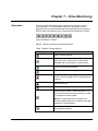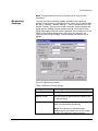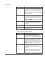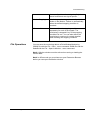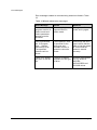
1
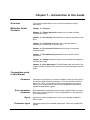
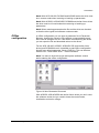
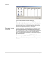
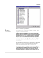
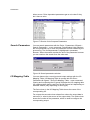
DriveWare User's Guide DriveWindow Light 2 DriveWindow Light 2 User's Guide DriveWare Code: 3AFE 64560913 EFFECTIVE: 22.11.2010 SUPERCEDES: 01.01.2010 2010 ABB Oy. All rights reserved. Table of Contents Table of Contents ............................................................................................................................................... iii Chapter 1 – Introduction to this Guide .......................................................................................................... 1-1 Overview .................................................................................................................................................. 1-1 What this Guide Contains ........................................................................................................................ 1-1 Conventions used in this Manual ............................................................................................................. 1-1 Parameter ...................................................................................................................................... 1-1 Drive dependent parameter ........................................................................................................... 1-1 Signal ............................................................................................................................................. 1-1 Parameter signal ........................................................................................................................... 1-1 Upload ........................................................................................................................................... 1-2 Download ....................................................................................................................................... 1-2 Online ............................................................................................................................................ 1-2 Offline ............................................................................................................................................ 1-2 Offline configuration ....................................................................................................................... 1-2 Backup ........................................................................................................................................... 1-2 Restore .......................................................................................................................................... 1-2 Wizard............................................................................................................................................ 1-2 ACS 100-400 and DCS400 drives ................................................................................................. 1-2 ACS800 series ............................................................................................................................... 1-2 Parameter Data ............................................................................................................................. 1-2 Chapter 2 – Overview ...................................................................................................................................... 2-1 Overview .................................................................................................................................................. 2-1 Chapter 3 – Getting Started ............................................................................................................................ 3-2 System Requirements ............................................................................................................................. 3-2 Installing DriveWindow Light .................................................................................................................... 3-2 NT4 ................................................................................................................................................ 3-2 Win2000 and WinXP ..................................................................................................................... 3-2 Starting DriveWindow Light ..................................................................................................................... 3-2 Connecting Drive and PC ........................................................................................................................ 3-2 Chapter 4 – Drive Status ................................................................................................................................. 4-2 Status Panel............................................................................................................................................. 4-2 Drive Status ................................................................................................................................... 4-2 Advanced Status ........................................................................................................................... 4-3 Status Bar ...................................................................................................................................... 4-3 Function Buttons ............................................................................................................................ 4-3 Online/Offline ........................................................................................................................................... 4-4 Chapter 5 – Parameters ................................................................................................................................... 5-2 Parameter Browser .................................................................................................................................. 5-2 Online Mode .................................................................................................................................. 5-2 Offline Mode .................................................................................................................................. 5-3 Parameter Group ........................................................................................................................... 5-4 Parameters & Signals .................................................................................................................... 5-4 Backup/Restore ....................................................................................................................................... 5-5 Offline configuration ................................................................................................................................. 5-7 Parameter Subset Selection .................................................................................................................... 5-8 DriveWindow Light 2 iii Table of Contents Compare Parameters .............................................................................................................................. 5-9 Search Parameters ................................................................................................................................5-10 I/O Mapping Table .................................................................................................................................5-10 Start-up Wizard ......................................................................................................................................5-11 External Applications .............................................................................................................................5-11 Adaptive Programming ..........................................................................................................................5-11 Sequence Programming ........................................................................................................................5-13 Main Window ...............................................................................................................................5-13 State Property Windows ..............................................................................................................5-14 Chapter 6 – Drive Control Panel ..................................................................................................................... 6-2 Operation ................................................................................................................................................. 6-2 Step Function ........................................................................................................................................... 6-3 Chapter 7 – Drive Monitoring .......................................................................................................................... 7-2 Operation ................................................................................................................................................. 7-2 Monitoring Settings .................................................................................................................................. 7-3 File Operations......................................................................................................................................... 7-5 Chapter 8 – Settings ........................................................................................................................................ 8-2 Communication Settings .......................................................................................................................... 8-2 Confirmation and Options ........................................................................................................................ 8-4 Chapter 9 – Error Messages ........................................................................................................................... 9-2 Parameter Browser .................................................................................................................................. 9-2 Backup/Restore ....................................................................................................................................... 9-3 Drive Status ............................................................................................................................................. 9-4 Drive Identification ................................................................................................................................... 9-4 Communication ........................................................................................................................................ 9-6 Monitor ..................................................................................................................................................... 9-7 Wizard ...................................................................................................................................................... 9-7 iv DriveWindowLight 2 Chapter 1 – Introduction to this Guide Overview The document describes how to use the DriveWindow Light 2 application. What this Guide Contains Chapter 2 – Overview Chapter 3 – Getting Started describes how to install and start DriveWindow Light. Chapter 4 – Drive Status describes how to monitor the status of the drive. Chapter 5 – Parameters describes how to operate with the parameters in online and in offline mode. Chapter 6 – Drive Control Panel describes how to control the connected drive. Chapter 7 – Drive Monitoring describes how to monitor drive operations. Chapter 8 – Settings describes how to view and edit the settings of DriveWindow Light. Chapter 9 – Error Messages of DriveWindow Light are listed in this chapter. Possible reasons and solutions for these messages are also listed. Conventions used in this Manual Parameter Parameters are frequency converter variables, which are brought up to users for adjusting drive operations. They are identified with four digits (e.g. 12.34). In this document the term parameter is used to refer not only to parameters but also drive dependent parameters, signals and parameter signals. Drive dependent parameter Drive dependent parameters are such that a default value cannot be defined in the parameter files. They are dependent on the particular drive rating values. Signal Parameter signal DriveWindow Light 2 Signals are read only parameters, which are cyclically updated in online mode. Parameter signals are writeable parameters, which are updated like signals. 1-1 Introduction to this Guide Upload Download Upload loads parameter values from the drive to Parameter Browser. Download writes parameter values from Parameter Browser to the drive. Online In online mode drive status and signals are uploaded cyclically from the drive to the PC and changed parameter values are written to the drive immediately. Offline In offline mode there is no communication between the PC and the drive without specific commands from the user. Offline configuration With offline configuration it is possible to change parameter values without a connected drive. Backup With backup operation parameters are uploaded from the drive straight to a PC file. Restore With restore operation parameters are written from a PC file straight to the drive. Note! Drive type and software version number together with the parameter file are checked when restoring. Wizard ACS 100-400 and DCS400 drives 1-2 Wizards are DLL-files, which are using DriveWindow Light’s communication module interface to talk with the drive. In this document the term ACS 100-400 and DCS400 drives is used when the features of DriveWindow Light are different depending on the type of the connected drive. The term includes the ACS140, ACS160, ACS400 and DCS400 drive series, where all the ACS drives belong to the range of the DriveIT Low Voltage AC Drives. ACS800 series The term ACS800 series is used in the same way as ACS 100-400 and DCS400 drives. The term includes the ACS800 drive series and if not otherwise mentioned the ACS600 drive series. Standard, pump and fan control together with spinning control applications are supported. The drives belong to the range of the DriveIT Low Voltage AC Drives. Parameter Data The term parameter data refers to all other information about a parameter than its actual value. That is: parameter's name, min and max values, unit and information concerning the way DWL processes the actual value. DriveWindow Light 2 Chapter 2 – Overview Overview DriveWindow Light is a start-up and maintenance tool for e.g. the ACS140, ACS160, ACS310, ACS320, ACS350, ACS355, ACS400, ACH400, DCS400, ACS550, DCS550, ACH550, ACS600, ACS800 and DCS800 drive series. DriveWindow Light is designed to run under the Microsoft Windows NT 4.0, Windows 2000, Windows XP, Windows Vista and Windows 7 operating systems on IBM-compatible PCs. The key functions of DriveWindow Light are the following: DriveWindow Light 2 Show the actual status of the connected drive Edit and show the drive parameters Save and load drive parameters Back up and restore drive parameters Offline configuration of drive parameters Graphical monitoring of drive signals Numerical monitoring of drive signals Run step response tests Control the drive Plug ’n Play connection of drives 2-1 Chapter 3 – Getting Started System Requirements To operate DriveWindow Light your computer must meet the following minimum requirements: Table 1 System Requirements Installing DriveWindow Light Category Minimum Requirement Processor Pentium 133 MHz Operating System Windows NT 4.0 (SP6), Windows 2000, Windows XP, Windows Vista or Windows 7 Display 1024x768, 256 colors System Memory (RAM) 64 MB Hard Disk Space 80 MB Insert the DriveWindow Light CD-ROM into the CD drive of your PC. NT4 Start Control Panel Double click on Add/Remove Programs Click the Install button Follow the instructions Win2000 and WinXP Start the Control Panel Double click on Add/Remove Programs Click the Add New Programs button Follow the instructions Note! When installing DriveWindow Light you must have Administrator privileges. Starting DriveWindow Light DriveWindow Light is started with a shortcut found in the DriveWare folder. Connecting Drive and PC To connect the drive and the PC you need different hardware depending on the drive type. On PC side you can use any free RS232 port. 3-2 DriveWindow Light 2 Getting started If you have an ACS310, ACS320, ACS350, ACS355 or ACS/ACH550 drive you need an OPCA-02 adapter. If you are working with a DCS400, DCS550 or DCS800 drive you do not need any other hardware components then a standard serial cable. You can connect the cable directly into the RS232 port of the drive. With other drives you need a standard serial cable and an appropriate adapter. If you are connecting an ACS140 or an ACS400 drive you must have an RS485/RS232 adapter. The adapter used with these drives is shown in Figure 1. For ACS160 drives a CFB-RS adapter is needed and to connect an ACS600 or ACS800 drive a panel link is established via an NPCU-01 adapter. If you do not have the adapter needed you may order one from a local ABB representative. Figure 1 RS485/RS232 Adapter DriveWindow Light 2 3-3 Chapter 4 – Drive Status Status Panel Drive Status Drive Status Panel is located on the left side of the DriveWindow Light main window. The status panel can be hidden or shown with the View - Drive Status Panel menu command. The upper part of the status panel shows information about the operation of the drive. It contains the following items for all drives: Drive type and its Modbus node number Drive remote/local mode (Auto / Hand-Off for ACH550) Running/stopped Running direction (forward or reverse) Drive state (OK, Warning or Fault) The name of the active fault or alarm. If the fault/alarm text is longer than the status panel, you can move the mouse cursor on it and see the text as a tool tip. Note! With ACS350, ACS/ACH550 and DCS800 (and similar) drives the modbus node number shown is usually 247, the default when communicating through the panel connector. This is different than the node number used when communicating through standard modbus fieldbus connector. The rest of the information about the drive operation varies between AC and DC drives. For AC drives the status panel contains the following items: Output frequency [Hz] Current [A] Power [kW] Speed [rpm] For DC drives the following items are displayed: DriveWindow Light 2 Armature voltage [V] Current [A] Power [kW] Speed [rpm] 4-2 Drive Status AC drives DC drives Figure 2 Drive Status Advanced Status Drive Advanced Status shows the status word and the control word of the drive. Advanced status is shown or hidden with the View Advanced Status menu command. Status and control words are shown in both binary and hexadecimal format. With ACS drives both Status Word and Control Word are frequently read from the drive. With DCS drives only Status Word is read from the drive and Control Word is the latest one sent to the drive. Figure 3 Drive Advanced Status Status Bar Status Bar, situated at the bottom of the screen, shows drive and connection status together with additional information on what the different menu commands and buttons affect. Status Bar is shown or hidden with the View – Status Bar menu command. Figure 4 Status Bar Function Buttons The lower part of Drive Status Panel contains the following function buttons: DriveWindow Light 2 Wizard - Opens the Wizard window Monitor - Opens the Monitor window 4-3 Drive Status Figure 5 Function buttons Online/Offline The state between online and offline is changed with the online/offline buttons in the Application Toolbar or with the Communication – Online and Communication - Offline menu commands. The Application Toolbar is shown or hidden with the View – Application Toolbar menu command. Table 2 Application Toolbar buttons Buttons Function Switch to online mode. Switch to offline mode. Upload all parameter values (and parameter data if it is read from the drive). Note! In offline mode also the status panel is updated. Figure 6 Application Toolbar and online mode With the ACS350, ACS/ACH550, DCS800 and similar future drives and ACS800 series the parameter data is not known beforehand, so the user is prompted to upload all data when changing to offline mode. Figure 7 Switching to offline with ACS350, ACS/ACH550 and DCS800 drives (or a similar future drive) and ACS800 series 4-4 DriveWindow Light 2 Drive Status The user has also the possibility to switch to offline with only the data he has uploaded in online mode. In this case only these parameters can be edited in offline mode. Parameter values (and parameter data when applicable) can be uploaded with the refresh button in Application Toolbar or with the Communication - Refresh menu command. DriveWindow Light 2 4-5 Chapter 5 – Parameters Parameter Browser You can use Parameter Browser to navigate parameters and signals and to modify parameter values. Parameters are organized as groups in a tree structure. Double clicking on the parameter group expands or collapses the group. You can also expand/collapse groups with the right/left arrow key or with the enter key. Parameter values can be modified by double clicking on the parameter or by pressing enter on a highlighted parameter. All parameter groups can be opened with the Drive – Parameters & Signals – Open All Parameters menu command. You can save the parameter names and values in a DriveWindow Parameter (DWP) file with the File – Save or File – Save as… menu commands. The parameters can be read from a DWP file and opened in the Parameter Browser with the File – Open or File – Open in Browser… (if you already have an open browser) menu commands. If you are in online mode the parameter file values are downloaded to the drive when you open a DWP file. These files are in ASCII or UNICODE format with semicolon delimiters and can be opened with most of the spreadsheet applications. Note! With ACS350, ACS/ACH550 and similar future drives the opening of the file and download may be cancelled if the drive doesn’t grant the start inhibit for the download time. Figure 8 Parameter Browser Online Mode DriveWindow Light 2 The basic idea of the online mode is that the values shown in the Parameter Browser should match the parameter values in the connected drive. The parameter values - and with ACS350, ACS/ACH550, DCS800 and similar future drives and ACS800 series also the parameter data - are uploaded automatically when the 5-2 Parameters parameter group is opened for the first time. Later the parameters can be uploaded with the refresh command. Signals are updated cyclically in the online mode. The modified parameter values are also immediately downloaded to the drive. In online mode with ACS350, ACS/ACH550, DCS800 and similar future drives and ACS800 series DriveWindow Light constantly monitors the drive for changes in the visible parameter set. If a change occurs the user is prompted to re-identify drive in order to achieve correct parameter data. The user can also continue with old data. With ACS350, ACS/ACH550, DCS800 and similar drives some minor changes are updated without prompting. Figure 9 Change of parameter structure with ACS800 series Note! Re-identifying the drive means that the connection to the drive is closed for a moment. Offline Mode In offline mode parameters are edited in RAM only. You can upload/download all the highlighted parameter values (or all values within the groups if you highlight the group name) with the Upload/Download command in the Drive - Parameters & Signals... menu. The command Upload All/Download All uploads/downloads also the values of not highlighted parameters/groups. DriveWindow Light asks for user confirmation for downloading if the confirmation is selected in the Options - Confirmation and Options table. After changing from offline to online mode the parameter values are uploaded. The application will ask if you want to download any changes you have made in offline mode before uploading. Note! DriveWindow Light doesn’t check drive type and software version with the download function. Note! With ACS800 series the Download All function doesn’t load parameter group 99. Note! With ACS310, ACS320, ACS350, ACS355 and ACS/ACH550 drives the Download All function loads also group 99, which means that if the drive ID run was performed earlier the ID run data is lost. DriveWindow Light 2 5-3 Parameters Note! With ACS350, ACS/ACH 550 and similar future drives a download may be cancelled if the drive doesn’t grant the start inhibit for the download time. The change of motor control mode changes a considerable amount of parameter data with ACS350 and ACS/ACH550 drives. If offline configuration has been started from a default PAR file the program suggests the user to change the PAR file in order to show correct data if the control mode is edited. Figure 10 Changing ACS350 or ACS/ACH550 drive's control mode in offline mode Note! Changing the PAR file means that the made changes to parameter values are lost if not downloaded to a drive (or saved to a file). Parameter Group Parameter Browser has the following icons to represent the different kinds of parameter groups: Table 3 Parameter group icons Icon Parameter Group Closed parameter group Open parameter group Closed subset selection group Open subset selection group Parameters & Signals Parameter Browser contains five different types of parameters. These types are identified with the icons shown in Table 4 Parameter icons. The most common type is parameter. Parameters are readable and writeable and their names, values and units are shown in Parameter Browser. A parameter's value is only read once, and if you want to update this value you have to request for it. There are also parameters, which are updated frequently, but accept only 0 as written value. Signals are like parameters, but you can't write their values. In online mode the value is updated cyclically in Parameter Browser. 5-4 DriveWindow Light 2 Parameters Parameter signals are also updated frequently and you can edit their values. In offline mode parameters are marked with a value-changed icon, when a new value is written or a previously saved parameter file is opened, but not yet downloaded to the drive. Drive dependent parameters appear only when you open a new offline drive. An offline drive always includes default values of the parameters, but not any values of drive dependent parameters (the values depend on motor, network, etc.). These values are not downloaded to the drive if you have not changed their values. A drive dependent icon is replaced with a value-changed icon when you write a new value to the drive dependent parameter. Note! For the ACS800 series, DCS550 and DCS800 there are no PAR files available, so you must have a previously saved file before offline configuration is possible. The adaptive parameters and the function of them are explained in the paragraph concerning Adaptive Programming. Table 4 Parameter icons Icon Parameter Parameter has no icon Signal Parameter signal Value changed in offline mode Drive dependent parameter Backup/Restore You can backup drive parameters to a file with the Drive - Parameters & Signals - Backup... menu command. Use the Drive - Parameters & Signals - Restore... menu command to restore a backup file to the drive. With ACS 100-400, DCS400 and ACS800 series the backup files are in ASCII or UNICODE format and have the extension DWB. With the ACS800 series both user data and ID run results are saved when backing up. The restore operation asks the user which of these he/she wants to restore. With ACS350, ACS/ACH550, DCS800 and similar future drives the backup files are encrypted binary files with the file extension VAR. DriveWindow Light 2 5-5 Parameters With these drives there may be several different restore options. See drive’s manual for details. The sets available in the selected file are enabled in the restore dialog. After the file is downloaded the differences between drive and file are shown and the values of these parameters can be edited at this point. If there were differences the downloaded values are saved to the drive memory only after user confirmation. If the user chooses ‘No’ the drive will be in the same state that it was before restore operation was started. Figure 11 Restore options with ACS350, ACS/ACH550, DCS800 and similar drives Figure 12 Download differences window Figure 13 Download confirmation 5-6 DriveWindow Light 2 Parameters Note! With ACS 100-400, DCS400 and ACS800 series the drive must be in remote mode when restoring or backing up parameters. Note! With ACS350, ACS/ACH550, DCS800 and similar future drives the drive must be in local mode when restoring or backing up parameters. Note! When restoring parameters the file and the drive are checked so that the drive types and software versions match. Offline configuration In offline configuration you can open a parameter file in Parameter Browser, change the values in office without a connected drive and then save all changes to a file. Later when commissioning the drives you can open the file and download values to the drives. For the ACS 100-400, ACS350, ACS/ACH 550 (and similar future drives) and DCS400 drives it is possible to start offline configuration directly from default parameter values (PAR file). This can be done with the File – New Offline Drive… menu command. Note! You have to know drive type and system software version before starting the offline configuration. Figure 14 New Parameter Document With ACS350, ACS/ACH550 and similar future drives you don’t need the software version but you need to know the control mode, localization and mains voltage. DriveWindow Light 2 5-7 Parameters Figure 15 New Parameter Document with ACS550 The user can also save parameters to a file (DWP file) and use this file for offline configuration. A previously saved file can be opened with the File – Open or File – Open in Browser… (if you already have an open browser) menu commands. In the Options - Confirmation and Options table you can configure DriveWindow Light to skip the automatic drive identification and start in offline mode. Parameter Subset Selection You can use the Drive - Parameters & Signals - Parameter Subset... menu command to create a virtual parameter group of your own. Click on the checkbox in front of the parameter to select it and use the '>>'-button to add, '<<' and '<< All' -buttons to remove parameters. The selected parameters are shown in the Selected Parameters pane. The created subset of parameters is shown as the first group in the Parameter Browser. Parameter subsets are saved into a SUBSET.DWP file. One subset for each drive type (ACS550, ACS800 for example) can be saved. Parameter subset selection dialog is also used to select parameters to monitor. 5-8 DriveWindow Light 2 Parameters Figure 16 Parameter Subset Selection Compare Parameters You can use the Drive - Parameters & Signals - Compare... menu command to compare parameters. In offline mode you can either compare parameter values between the active parameter browser and a freely selected DriveWindow Parameter (DWP) file or between the active parameter browser and the connected drive. The file in the active browser can be either a default file (PAR) or a file that has been saved by the user (DWP). In online mode you can only compare parameter values between the active parameter browser and a DriveWindow Parameter (DWP) file because the values in the active browser are the ones from the connected drive. The Result window shows the differing parameter/group names in the first column. The second column shows the value in the active browser and the third column the value in the drive or file. The comparison is based on parameter number, which consists of group number and the parameter’s index within the group. The values of the parameters are compared only if both the numbers of the parameters and their names are the same. Otherwise the result shows that the parameter or parameter group is missing (n/a) from DriveWindow Light 2 5-9 Parameters either source. Drive dependent parameters get an n/a value if they don’t have a value. Figure 17 Results of the Compare Parameters Search Parameters You can search parameters with the Drive - Parameters & Signals Search Parameters… menu command. DriveWindow Light searches the next parameter up or down the parameter browser containing the given string. The found parameter is highlighted in parameter browser. When the search reaches the end of the parameter browser you can continue the search from the other end. Figure 18 Search parameters window I/O Mapping Table You can observe the current input and output settings with the I/O Mapping Table. I/O Mapping Table is opened with the Drive Parameters & Signals - Show I/O Mapping Table... menu command. Closing and re-opening the I/O group refreshes the I/O mapping data. I/O mapping table data is read from the INI file and isn't depending on software version (only depending on drive type). The first column in the I/O Mapping Table shows the name of the corresponding I/O. For outputs the second column shows from where the output data is retrieved (i.e. what is the source of the output data). The third column shows the number of the parameter, which is used to configure the corresponding output. 5 - 10 DriveWindow Light 2 Parameters For inputs the I/O Mapping Table shows which inputs have been configured to affect some attribute in the drive. The second and third columns show the name and the number of the parameter where the configuration has been done. Figure 19 I/O Mapping Table I/O Mapping table is offered for e.g. ACS 100-400 series, ACS310, ACS350 and ACS/ACH550 drives. Start-up Wizard DriveWindow Light includes start-up wizards for e.g. ACS310, ACS350, ACS/ACH550 and DCS400 drives. You can start a wizard with the Drive - Launch Wizard… menu command or by pressing the Wizard button in Status Panel. To start a wizard you must have an online connection to a drive that has a wizard. External Applications DriveWindow Light offers the possibility to launch some external applications through its user interface. The external applications can be found under Tools menu. The applications are installed during the DriveWindow Light installation. The user interface of DriveWindow Light is frozen for the time that the other application is running. Adaptive Programming The ACS800 drives with Standard application software (not the ACS600 series) have a feature called Adaptive Programming. Adaptive Programming consists of a set of blocks, which can be programmed to perform any of a predefined set of functions. It is like having a small PLC inside the drive. The user can freely define inputs to the blocks, wiring between the blocks and connections to the drive I/O or to the drive control. In this way the user is able to create new input and output signals and modify the drive’s speed or torque control. DriveWindow Light 2 5 - 11 Parameters Figure 20 Adaptive parameters The adaptive parameters are found in group 84. Some of these parameters have a little special format but they are in principle common parameters,. The accepted values for them are either in pointer form or constant form. In DriveWindow Light the parameters are given as strings, which must be in the right format. The application doesn’t guide the user for the format when editing, but if the input is incorrect the right format is shown in the error message. Table 5 Format of adaptive parameters Format Parameter values ±.xxx.yyy.zz denotes the pointer form. If minus sign (-) is selected the value read is inverted. Xxx = parameter group number (0-255), yyy = parameter number (0-255) and zz = bit number (0-31) C.xxxxx C denotes constant form. Xxxxx = value (-32768 - 32767) 5 - 12 DriveWindow Light 2 Parameters For more information about Adaptive Programming refer to the Adaptive Programming Guide, the manual concerning this subject. Sequence Programming Tool The ACS350 and ACS355 drives have a feature called Sequence Programming (for short: SP). To ease the use of this feature DriveWindow Light Includes a Sequence Programming Tool, which can be launched with a menu command Tools – Sequence Programming Tool. Figure 21 Sequence Programming Tool, main window The Sequence Programming Tool has basically three types of windows: the main window, state property windows and common settings windows. In the main window of the SP Tool are the tool’s menus and the state diagram of the sequence program. The parameters of the states are edited in the property windows. In the common settings windows the user can edit other parameters related to SP. The SP program can be saved to a PC file simply by saving drive’s parameters to DriveWindow Light’s parameter file (the menu command File – Save or File – Save As in DriveWindow Light). The SP parameters are saved together with all other parameters. For detailed information of the sequence programming feature of the drive see drive’s user manual. Main Window DriveWindow Light 2 The SP main window is shows the state diagram of the sequence program. The diagram shows the states and the state transitions. The 5 - 13 Parameters parameters of each state are shown in a read only format. If DriveWindow Light is in online mode the diagram is drawn based on the information uploaded from the connected drive. In offline mode the information is read from file. All states which have a transition to some other state are shown in the diagram. A state is shown also if some other state has a transition to it. So to add a state to a program the user must either add a transition to that state or a transition from that state. To remove a state the user has to remove all transitions from that state and also all transitions to that state. The first state is always shown since all programs start from state one. The bolded border of the state denotes that the state is active at the moment. In the main window you can show the SP toolbar with the menu command View – SP Toolbar. The toolbar has buttons to start, stop, pause or reset the SP program. It also has a combo box and buttons to force the program to a given state (the SP program has to be running and paused) or to jump to editing given state’s properties. Figure 22 SP toolbar In the Drive –menu are found the up- and download commands to load all SP related parameters. This means the whole parameter group 84, which is the actual SP group but also all other parameters that can be associated with the SP. In other words all parameters found under the Common settings –menu. For documentation purposes there are a couple of options. In the File –menu there are commands to print either the state diagram or the common settings as a parameter list. With the Edit – Copy diagram – menu command you can copy the state diagram as a bitmap and then paste it to any application supporting that format. 5 - 14 Common Settings Windows From the Common Settings –menu the user can open a selection of windows. In these windows are found the parameters that may affect to or can be manipulated from the SP program but are not directly associated to any state. State Property Windows The parameters of a state are edited in the states’ property windows. A property window includes all parameters that are specific to that state. State’s property window can be opened by clicking the Edit button of the state or by selecting the wanted state from the SP toolbar and clicking toolbar’s Edit button. From each property window you can also go either to the previous state or to the next state (in numerical order). DriveWindow Light 2 Parameters Figure 23 Window for editing state’s parameters DriveWindow Light 2 5 - 15 Chapter 6 – Drive Control Panel Operation You can use Control Panel to control the drive operation. Control Panel can be shown or hidden with the View - Drive Control Panel menu command. You can also find all drive operation commands from the Drive - Control Panel menu. Control Panel has the following buttons: Table 6 Drive Control Panel buttons Buttons Function Switch between local and remote mode. The button is checked when local mode is active. For example ACH550 drives have auto button instead of Local/Remote shown above. Auto button switches to the auto mode if the drive was in hand-off mode. The button is checked when the auto mode is active. Reset active fault on drive Start the drive (ACH550: change to the hand mode if not already and start the drive) Stop the drive (ACH550: change to the off mode if not already and stop the drive) Run forward (For AC drives only) Run reverse (For AC drives only) Close contactor (For DC drives only) Open contactor (For DC drives only) Speed reference edit box Download the speed reference to drive Execute step function In online mode the local/remote button (auto button with for example ACH550) is always active with all drives. The reset button is always active with ACS350, ACS/ACH550, DCS800 and similar future drives. With ACS350 and ACS/ACH550 (and similar) the speed reference editing is active also in remote mode if the drive expects a reference from the tool/panel link. The other Control Panel buttons are enabled only when switched to local mode (hand-off mode with for example ACH550). In offline mode all the Control Panel buttons are disabled. DriveWindow Light 2 6-2 Drive Control Panel Figure 24 Drive Control Panel Step Function You can use step function to execute step response tests for the drive. Step function alters the external speed reference with a given value for a given time. Step function is triggered from the Drive - Step Function - Run Step Function menu command or from the Control Panel button. Step function is configured with the Drive - Step Function - Step Function Settings... menu command. Figure 25 Step Function Settings You can configure the speed reference step size (negative or positive) and the duration of the step. Default step size is 1 % of the current speed reference and the default duration of the step is 1000 ms. DriveWindow Light 2 6-3 Chapter 7 – Drive Monitoring Operation You can use DriveWindow Light to monitor the operation of your connected drive. The operational values can be shown in both graphical and numerical format and monitoring data can be saved to a file for later use. Monitoring is controlled with the Monitor Toolbar. Figure 26 Monitor Toolbar Monitor Toolbar contains the following buttons: Table 7 Monitor Toolbar buttons Button Function Open monitor settings Start lasso zoom. An area can be selected with the mouse. Lasso zoom mode can be disabled with a second click on this button. Zoom in the trend line graph Zoom out the trend line graph Clear the monitoring data from the numeric screen, from the graph and from application's memory Start monitoring Stop monitoring Show monitor data in numerical format. You can open several numerical windows in order to compare monitoring data. Note! In numerical format the values are shown multiplied with the coefficient set either manually or automatically. Activate auto scroll. Scrolls automatically to the rightmost position. DriveWindow Light 2 7-2 Drive Monitoring Note! The application has to be in online mode in order to start monitoring. Monitoring Settings You can select the monitored signals and define the monitoring settings in the Monitoring Settings window, which can be opened with the Drive – Monitor – Monitor Settings… menu command or from the Monitor Toolbar. There are two kinds of settings: Global settings and signal specific settings. Signal specific settings can be set to each signal individually when the signal is selected in the combo box in the middle of the Settings dialog box (1.02 Speed is selected in the Figure 22 Monitoring Settings). Global settings are identical for all signals. Figure 27 Monitoring Settings Table 8 Global monitoring settings Dialog Item Meaning Sample Interval (ms) Sample interval in milliseconds. Manual Y-axis Set the minimum and maximum values of the Y-axis manually. Auto Y-axis The minimum and maximum values of the Yaxis are calculated automatically. Note! The values are calculated when enabling auto mode and when in auto mode closing the parameter subset selection DriveWindow Light 2 7-3 Drive Monitoring window. Max Y-axis Maximum Y-axis value. In Auto Y-axis mode the value for Y-axis maximum is the biggest maximum value of the monitored parameters. Note! The positive Y-axis values are limited to be under 200 000. Min Y-axis Minimum Y-axis value. In Auto Y-axis mode the value for Y-axis minimum is the smallest minimum value of the monitored parameters. Note! The negative Y-axis values are limited to be over -200 000. Amount of Samples The number of samples stored in the RAM. The value should be between 1 000 and 1 000 000. X-axis length The length of the X-axis in seconds. Enable Point Marks Show point marks to represent actual samples in the trend lines. Table 9 Signal specific monitoring settings Dialog Item Meaning Select Select a maximum of four signals for monitoring. Monitoring signals are selected with the parameter subset selection dialog. Manual Coefficient Set the coefficient value for the signal selected in the drop down list. The actual sample values received from the drive are multiplied by this value. Coefficients can be used to scale signals in order to improve clarity. Auto Coefficient The coefficients are calculated automatically based on the maximum values of the monitored signals and the maximum value of the Y-axis. Note! Auto coefficients are calculated when the Monitoring Settings window is closed. Note! Manual or Auto Coefficient selection is 7-4 DriveWindow Light 2 Drive Monitoring the same for all monitored signals. Only the actual coefficients are signal specific. File Operations Monitor Stopping Monitoring can be stopped manually with the button in the Monitor Toolbar or automatically when the defined stopping condition is reached. After conditions You can define the stopping condition separately for each of the signals. The monitoring is stopped if any of the stopping conditions is true. You can also define the monitoring to continue for certain duration after reaching the stopping condition. You can save the monitoring data to a DriveWindow Monitoring (DWM) file with the File - Save... menu command. DWM files can be loaded with the File - Open In Monitor... menu command. Note! A Monitor window must be active when saving or loading the monitor data. Note! In offline mode you must have an open Parameter Browser before you can open the Monitor window. DriveWindow Light 2 7-5 Chapter 8 – Settings Communication Settings You can configure the communication settings with the dialog window opened with the Communication - Communication Settings... menu command. In auto mode DriveWindow Light uses first the communication settings that are the default settings for ACS 100-400 (primary settings) and then the default settings of DCS400 drives (secondary settings). With both settings the application scans the bus also with ACS800 series type of identification. The ACS/ACH550 type of identification is done with the primary settings. The communication (COM) port can be selected with the drop down list in the Auto-Mode Settings. Table 10 Communication Settings in auto mode Setting Primary Settings Secondary Settings Baud Rate: 9600 9600 Data: 8 8 Parity: None Odd Stop: 2 1 Modbus Address 1 … 10, 247 with ACS350, ACS/ACH550 and similar 1 … 10 You can also check the User Defined check box to define your own communication settings. In order to identify the ACS800 series in this mode you'll have to mark the ACS800 series identifying check box. Otherwise DriveWindow Light will search only for ACS 100-400, ACS350, ACS/ACH550 (and similar) and DCS400 drives. Possible values for settings are the following: Table 11 User Defined Communication Settings DriveWindow Light 2 Setting Possible values Port: All com ports on your PC 8-2 Settings DriveWindow Light 2 Baud Rate: 9600 … 115200 Data: 7 bit or 8 bit Parity: None, Odd or Even Stop: 1 or 2 Modbus Address 1 … 255 8-3 Settings For the timeout setting there are no actual limits. After the timeout DriveWindow Light judges that there will be no answer to the previous question and tries again. Note! With Auto settings the identification is done with constant timeout of 400 ms. If longer timeout value during identification is needed, use User Defined settings. Note! With ACS350, ACS/ACH550 and similar drives the communication speed mentioned here is the speed used at identification. After identification the communication speed is automatically set to the highest possible i.e. 115200 bit/s. Note! Use User defined settings: 38400 bit/s, 8 bits, odd, 2 and 247 to communicate with DCS550 or DCS800. Figure 28 Communication Settings Confirmation and Options 8-4 You can configure DriveWindow Light to start in either online or offline mode. You can also configure DriveWindow Light to show confirmation dialogs for critical operations. These configurations can be set in the Confirmation and Options window opened with the DriveWindow Light 2 Settings Options - Confirmation and options... menu command. For example if you select Drive Start, the application asks ‘Are you sure you want to start the drive?’ when you have requested to start the drive. Default settings are shown in the figure below. Figure 29 Confirmation and Options DriveWindow Light 2 8-5 Chapter 9 – Error Messages Parameter Browser Parameter Browser related error messages are listed in Table 12. Table 12 Parameter Browser related error messages DriveWindow Light 2 Error Message Cause Solution Can't compare parameter browser and Drive in bus because parameter browser does not have a software version number. Perhaps parameter browser is opened from a file. Proceed to the online mode? The opened document does not include any identification data. Select proper drive type and the software version manually. Can't continue compare operation because Drive was not found. Trying to compare parameters between the parameter browser and a drive, but no drive is found. Check the connection to the drive and try again. Given value was invalid. Please input valid value. The value you are trying to give does not fit between minimum and maximum values of the parameter. Check the minimum and maximum values and give a proper value. Operation is not possible in Local mode. Change to Remote mode. Open and save functions are not available in local mode. Switch to remote mode and try again. Could not write value. This parameter accepts only 0 as written value. The parameter is of a type that doesn’t accept any other value to be written than 0, which resets the parameter. Write 0 if you want to reset the parameter. 9-2 Error Messages Error occurred while uploading parameters. Check the connection and try again. The connected drive’s application software is not supported by DWL. Product family of the parameter file differs. Download is cancelled. Press OK to enter offline mode. DWL is in the online mode and the parameter file you are trying to open is for different type of drive than the one that is connected. Access to …\cdwl2.ini was denied. Backup/Restore Switch to offline mode or select a proper parameter file. You must have Administrator privileges to avoid this error message. Error messages related to Backup/Restore functionality are listed in Table 13. Table 13 Backup/Restore error messages Error Message Cause Solution Download not allowed, incomp. Drive type (SAP Error code: 0x215) The backup file that you are trying to restore to the drive is from a different drive type. Choose a file saved from a similar drive that you’re connected to. Parameter download failed, too much differences (SAP error code: 0x219) There were so many differences during the download that the operation could not be finished. Parameter download failed 1. You chose ‘No’ to the parameter save confirmation 1. Everything is OK 2. Try again 2. Some unspecified error occurred DriveWindow Light 2 9-3 Error Messages Unable to perform restore! Target has old download interface and backup file has been done with new download interface Drive Status Restore is not possible due to differences in the drive software of the backup file and the connected drive. Drive status related error messages are listed in Table 14. Table 14 Drive status related error messages Drive Identification Error Message Cause Solution Some errors occurred while updating Status panel. Error(s) occurred in the update procedure. Check the connection and try again. The drive in bus is changed, proceed to online mode and reidentify drive? If continued to online mode, all current information in parameter browser will be lost. The connected drive has been changed. Select OK to switch to online mode and to update the contents of the Parameter Browser. Select cancel to switch to offline mode and keep the contents of the Parameter Browser unchanged. You’re entering offline mode. In offline mode you don’t have access to parameters whose data you haven’t uploaded. Do you want to upload all parameter data before entering to the offline mode? With the ACS350, ACS/ACH550, DCS800 (and similar future drives) and ACS800 series the parameter data is not known beforehand, so the user is prompted to upload all data when changing to offline mode. Select yes if you want to upload all parameter data and switch to offline mode. Select no to switch to offline without uploading any data or cancel to stay in online mode. Drive identification related error messages are listed in Table 15. Table 15 Drive identification related error messages 9-4 DriveWindow Light 2 Error Messages Error Message Cause Solution Could not find drive, scans failed. Returning to Offline mode. Cannot switch to online mode. Either there is no drive connected or the communication settings are wrong. Check the connection to the drive and the communication settings and try again. The drive in the bus doesn't have serial number, so the identification was done by comparing software versions. Software versions were the same, but the drive may still be different. Proceed to the online mode? DWL cannot uniquely identify the drive. The drive type and SW version are the same but the DWL cannot read the serial number from the drive. Select yes to switch to online mode. Select no to switch to offline mode. Detected unsupported Drive software product. DriveWindow Light supports Spinning Control, Standard and Pump&Fan Control Applications. Do you want to continue with the Standard Application support? The connected drive’s application software is not supported by DWL. Select yes if you want to continue with the Standard Application support. Select no if you want to use DriveWindow Light like parameter tool (control panel is disabled). No drive detected. DWL cannot find any drive. Either there is no drive connected or the communication settings are wrong. Check the connection to the drive and the communication settings and try again. The lower modbus address must be smaller than the higher address. DriveWindow Light 2 Set the values correctly. 9-5 Error Messages Communication The drive in bus is changed. Proceed to online mode and reidentify drive? If continued to online mode, all current information in parameter browser will be lost. The drive connected to the bus is of different type or software version than the one that has been in offline mode. If you don't want to lose the modifications made in offline mode click no and save your data. You must select drive and version. You must select drive type and software version to create a new offline parameter set. Select the drive type and software version. Communication related error messages are listed in Table 16. Table 16 Communication related error messages 9-6 Error Message Cause Solution CRC error. CRC check sum contains an error. Try again. Error opening COM port. DWL is not able to open the COM port. This happens if the COM port is not properly set in the communication settings or if another application is using the COM port. Check the communication settings, close other applications that are using the same COM port and try again. DriveWindow Light 2 Error Messages Monitor Modbus device returned an exception code xxx. (1 = Illegal function, 2 = Illegal data address, 3 = Illegal data value, 6 = slave device busy.) Modbus exception number xxx occurred. Code 1 means that the drive doesn't support the used function. Code 2 indicates that there is a parameter in the used parameter file which doesn't exist in the drive. Code 3 means that the given value is out of the limits accepted by the drive. Code 6 can occur if the drive is doing some action, which prevents parameter writes for some time. For further information check the error code from the User's Manual of the connected drive. Time Out Error. Drive response time exceeded the length of the time out period. Check the connection and try again. Returned invalid device response. DWL cannot find sofware version information from the parameters 33.01 and 33.02. Probably software version of the Drive is unsupported, you can still use DriveWindow Light like parameter tool. Monitoring related error messages are listed in Table 17. Table 17 Monitoring related error messages Error Message Cause Solution Start of drive monitoring is not possible in Offline mode. In order to get values for monitoring from drive DWL must be in online mode. Change to online mode and try again. Wizard DriveWindow Light 2 9-7 Error Messages Error messages related to commissioning wizard are listed in Table 18. Table 18 Wizard related error messages 9-8 Error Message Cause Solution To launch wizard, program must be in Online mode and Online parameter browser must be activated. You are trying to launch Wizard in offline mode. Change to online mode and try again. Can't load Wizard file: C:\Program files\… System returned an error: The specified module can't be found. The wizard DLL that is specified for the drive type and software version in question cannot be found. Check from the drive type's INI file that the path to find the wizard is correct and the wizard is named correctly. There is no wizard file given in the INI file. There is no wizard available for this type of drive. Wizards are available for e.g. ACS310, ACS350, ACS/ACH550 and DCS400 drives. DriveWindow Light 2 3AFE 64560913 22.11.2010 ABB Oy Drives P.O.Box 184 FI-00381 HELSINKI FINLAND Telephone Telefax Internet + 358 10 22 11 + 358 10 22 22681 http://www.abb.com/motors&drives