1
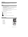
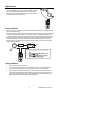
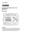
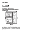
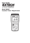
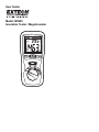
User Guide
Model 380260
Insulation Tester / Megohmmeter
Introduction
Congratulations on your purchase of Extech’s Insulation Tester/Megohmmeter. The Model
380260 provides three test ranges plus continuity and AC/DC voltage measurement. A handy
test lock feature and a data hold function are also included. This professional meter, with
proper care, will provide years of reliable service.
Safety
1.
Circuits under test must be de-energized and isolated before connections are made
(except for voltage measurements).
2.
Circuit connections must not be touched during a test. Use extreme caution when
working near bare conductors and bus bars. Accidental contact with conductors could
result in electrical shock.
3.
Use caution when working near voltages above 60VDC or 30VACrms.
4.
After insulation tests, capacitors must be discharged.
5.
Test leads (including alligator clips) must be in good working order, clean and without
broken or cracked insulation.
6.
When servicing, use only specified replacement parts.
International Safety Symbols
Caution, refer to this manual before using this meter
Dangerous Voltages
Meter is protected throughout by double or reinforced insulation
Meter Description
1. LCD Display
2. Hold Button
3. Test Button
4. Rotary Switch
5. Backlight Button
6. Lock Button
7. Input Terminals
2
380260-EU-EN-V 2.3-3/11
Operation
Warning
Ensure that the circuit under test does not include components that can be damaged by 1000VDC; such
devices include power factor correction capacitors, low voltage mineral insulated cables, electronic light
dimmers, and ballasts/starters for fluorescent lamps.
Connecting Test Leads
For all measurements, connect the red test lead to the VΩ input terminal and the black
test lead to the COM input terminal.
Test Lead Check
1.
Set the rotary switch to the 200Ω
2.
Touch the test lead tips together.
range.
3.
Resistance should read less than 0.5Ω and the audio tone should sound.
4.
With the leads not touching, the display should read infinity indicated by “1”.
5.
Readings displayed other than the readings described above are indicative of a test
lead problem. The test leads must be replaced before using the meter. Failure to do
so could result in damage to equipment and electrical shock.
Insulation Resistance Measurements (Megohmmeter Tests)
Warning: Do not perform Insulation Resistance measurements if AC Voltage is present on the
device under test.
1. Connect the red test lead to the VΩ input terminal; black lead to the COM terminal.
2. Set the function switch to the desired MΩ test voltage position.
3. Connect the tips of the test leads to the equipment under test. If there is a voltage
present, a constant beep will sound and the voltage will be displayed.
4. The display will show “1“until the TEST button is pushed. Press and hold the TEST
button. The upper right display shows the test voltage applied and the flashing high
voltage symbol
will be displayed. The main display shows the resistance.
5. Keep the test leads connected to the equipment under test and release the TEST
button. The circuit will discharge through the meter. Keep the test leads connected
until the circuit is completely discharged and the upper right display shows 0 volts.
Lock Function
For hands-free operation, use the LOCK feature.
1. With the test leads connected to the equipment under test, simultaneously press the
TEST and LOCK keys.
” will appear on the display. A beeper will sound every 2
2. The LOCK icon”
seconds to indicate that the meter is in Lock mode.
3. Press the LOCK key to disable the Lock function and end the test.
3
380260-EU-EN-V 2.3-3/11
Notes on IR (Megohmmeter) testing:
1.
The maximum measurement range for the 380260 is 2000MΩ. Frequently, insulation
resistance will exceed this value. When this happens, the display will indicate “1”,
meaning the resistance is very high and the insulation being tested is good.
2.
If the device being tested is highly capacitive, the display will indicate an increasing
resistance value over time. Always wait until the reading has stabilized before
recording the value.
AC/DC Voltage Measurement
1. Set the Rotary switch to the ACV or DCV position.
2. Connect the red test lead to the VΩ terminal and the black test lead to the COM
terminal.
3. Connect the test leads to the circuit under test.
4. Read the voltage value on the LCD.
Resistance Measurement
WARNING
Do not run this test unless ACV = 0. Do not use this mode to check diodes.
1. Set the Rotary switch to the 200kΩ position.
2. Connect the red test lead to the VΩ terminal and the black lead to the COM terminal.
3. Connect the tips of the test leads to the circuit under test.
4. Read the resistance value on the display.
Low Resistance (Continuity) Measurement
1. Set the Rotary switch to the 200Ω
position.
2. Connect the red test lead to the VΩ terminal and the black lead to the COM terminal.
3. Connect the tips of the test leads to the circuit under test.
4. Read the resistance value on the display. When the resistance of a circuit is less than
approx. 40Ω, the audible tone will sound.
Auto Power Off
To conserve battery life, the meter will automatically turn off after approx. 15 minutes of
non-use. To turn the meter back on, turn the rotary switch to OFF, then to the desired
function.
Hold Function
The hold function freezes the reading in the display. Press the HOLD key momentarily to
activate or to exit the hold function
Backlight
Press the
key for to turn on the display backlight function. The backlight will
automatically turn off after 15 seconds.
4
380260-EU-EN-V 2.3-3/11
Applications
Measuring Power Tools and Small Appliances
This section applies to any device under test that uses a line
cord. For double insulated power tools, the meter’s leads
should be connected to the device’s housing (chuck, blade,
etc.) and the lines of the power cord.
Testing AC Motors
Disconnect the motor from the line by disconnecting the wires from the motor terminals or
opening the mains switch.
If the mains switch is opened, and the motor also has a motor-starter, then the starter must
be held in the ON position. With the mains switch opened, the measured resistance will
include the resistance of the motor wire and all other components between the motor and
the main switch. If a weakness is indicated, the motor and other components should be
checked individually. If the motor is disconnected at the motor terminals, connect one
meter lead to the grounded motor housing and the other lead to one of the motor leads.
Refer to diagram at below.
Motor
GND
Mains
Switch
Starter
Line
Notes:
1. The STARTER must be in the ON position during the
Testing DC Motors
1.
Disconnect the motor from the line.
2.
To test the brush rigging, field coils and armature, connect one meter lead to the
grounded motor housing and the other lead to the brush on the commutator.
3.
If the resistance measurement indicates a weakness, raise the brushes off of the
commutator and separately test the armature, field coils and brush rigging (one at a
time). Leave one lead connected to the grounded motor housing while testing the
motor components. This also applies to DC Generators.
5
380260-EU-EN-V 2.3-3/11
Testing Cables
1.
Disconnect the cable under test from the line.
2.
Disconnect the opposite end of the cable to avoid errors as a
result of leakage from other equipment.
3.
Check each conductor to ground and/or lead sheath by
connecting one meter lead to ground and/or lead sheath and
the other meter lead to each of the conductors in turn.
4.
Check insulation resistance between conductors by
connecting meter leads to conductors in pairs. Refer to
diagram at right.
Specifications
Range Specifications
o
o
Accuracies are specified as % reading + digits at 23 C ± 5 C < 80% RH
MEGOHMMETER RANGES
Range
Resolution
Accuracy
200MΩ/250V
0.1MΩ
±3% + 5d
250V + 10% ~ -0%
200MΩ/500V
0.1MΩ
±3% + 5d
500V + 10% ~ -0%
0-1000MΩ/1000VDC
1MΩ
±3% + 5d
1000V + 10% ~ -0%
1000-2000MΩ/1000VDC
1MΩ
±5% + 5d
1000V + 10% ~ -0%
Range
Terminal Voltage
Test Current
200MΩ/250V
Short Circuit Current
250kΩ (load)
200MΩ/500V
0-1000MΩ/1000VDC
1mA
500kΩ (load)
<1mA
1MΩ
1000-2000MΩ/1000VDC
AC VOLTAGE (40Hz-400Hz)
Range
Resolution
750VAC
Accuracy
Input
Impedance
1V
±1.2% + 10d
10MΩ
Resolution
Accuracy
Input
Impedance
Overload
Protection
750Vrms
DC VOLTAGE
Range
1000VDC
1V
±0.8% + 3d
10MΩ
Overload
Protection
1000Vrms
RESISTANCE
Range
Resolution
Accuracy
Max. Open
Circuit Voltage
Protection
Overload
200Ω
0.1Ω
±1% + 2d
4.5V
250Vrms
200kΩ
0.1kΩ
±1% + 2d
3V
250Vrms
6
380260-EU-EN-V 2.3-3/11
General specifications
Display
LCD with dual display
Sampling rate
2.5 readings per second
Continuity beeper
<40Ω, short circuit current <200mA, open circuit voltage
4.5V
Over range indicator
‘1’ displayed
Zero adjust
Automatic
Low battery indicator
Low battery symbol displayed when battery voltage is low
Environmental
Installation category II, Pollution Degree 2, Altitude up to
2000 meters, Indoor use only
Power source
Six (6) 1.5 ‘AA’ batteries
Fuse
250mA/600V ceramic 3AG Fast blow
Operating conditions
0 to 40 C (32 to 104 F); 80% RH
o
o
o
o
Storage conditions
-10 to 460 C (14 to 140 F); <80% RH
Dimensions
200 x 92 x 50mm (7.8 x 3.6 x 1.9”)
Weight
700g (24.6oz)
IEC 1010
Approvals
CAT III-1000V
7
380260-EU-EN-V 2.3-3/11
Maintenance
Battery Replacement
When the low battery symbol
appears on the LCD, the six
1.5V ‘AA’ batteries must be replaced.
1. Turn the meter off and remove the test leads
2.
Unsnap the tilt stand from the rear of the meter
3.
Remove the four Phillips head screws holding the battery
cover
4.
Remove the battery compartment cover
5.
Replace the batteries observing polarity
6.
Affix the rear cover and secure the screws.
7.
Reattach the tilt stand
You, as the end user, are legally bound (EU Battery ordinance) to return all
used batteries, disposal in the household garbage is prohibited! You can
hand over your used batteries / accumulators at collection points in your
community or wherever batteries / accumulators are sold!
Disposal: Follow the valid legal stipulations in respect of the disposal of the
device at the end of its lifecycle
Cleaning
Periodically wipe the case with a dry cloth. Do not use solvents or abrasives to clean this
instrument.
Copyright © 2011 Extech Instruments Corporation (a FLIR company)
All rights reserved including the right of reproduction in whole or in part in any form.
8
380260-EU-EN-V 2.3-3/11