1
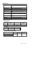
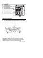
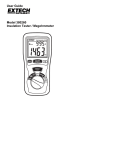
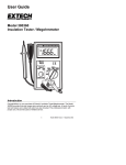
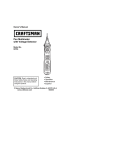
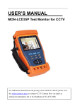
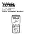
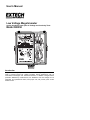
User's Manual
Low Voltage Megohmmeter
Analog Insulation Tester plus AC Voltage and Continuity Tests
Model 380350
Introduction
Congratulations on your purchase of Extech’s Low Voltage Megohmmeter. This
meter is geared toward low voltage insulation testing applications such as
Information Technologies and Telecommunications. In addition to Megohmmeter
(Insulation Resistance) measurements, low Resistance and AC Voltage can be
measured. This professional meter, with proper care, will provide years of safe
reliable service.
Safety
1.
2.
3.
4.
5.
6.
Circuits under test must be de-energized and isolated before
connections are made (except for voltage measurements).
Circuit connections must not be touched during a test. Use extreme
caution when working near bare conductors and bus bars. Accidental
contact with conductor could result in electrical shock.
Use caution when working near voltages above 60VDC or 30VACrms.
After insulation tests, capacitors must be discharged.
Test leads (including alligator clips) must be in good working order, clean
and without broken or cracked insulation.
When servicing, use only specified replacement parts.
International Safety Symbols
Caution, refer to this manual before using this meter
Dangerous Voltages
Meter is protected throughout by double or reinforced insulation
Rated Environmental Conditions
•
Indoor use only
•
Installation Category III
•
Pollution degree 2
•
Altitude up to 2000 meters
•
Ambient conditions: Temperature: 32 to 104oF (0 to 40oC); RH: 80% max.
2
380350
V1.4 11/2003
Specifications
General specifications
Display
Insulation test ranges
AC Voltage test
Low Resistance
Live circuit indicator
Withstand voltage
Power source
Power consumption
Fuse protection
Operating conditions
Dimensions
Weight
Taut band multi-scale analog display with Power
Test and Live Circuit status LEDs and zero screw
adjust
20/50/100MΩ (50V/125V/250V) tests
600VAC measurements (40 to 1kHz)
0 to 50Ω
LED lights when live circuit is sensed
Meets IEC-1010 safety requirements for Cat. III
600V
Eight 1.5 AA cells included
Megohmmeter: 160mA max.; Continuity: 120 mA
max.
250V (1A) for Insulation Resistance and Continuity
Tests
32 to 104oF (0 to 40oC); < 80% RH
6.7 x 6.5 x 3.6” (170 x 165 x 92mm)
2.1 lbs (970g)
Range Specifications
Low Resistance
Range
Max. open circuit
Volt
600mV (240mA)
0 to 50Ω
Accuracy
Overload
Protect.
250Vrms
±5% of scale
length
AC Voltage
Range
600VAC
Accuracy
±2.5% of full
scale
Line Frequency
40 to 1kHz
Insulation Resistance / Megohmmeter
Range
0 to 20MΩ (50VDC ±10%)
0 to 50MΩ (125VDC ±10%)
0 to 100MΩ (250VDC ±10%)
Accurac
y
±5% of
reading
3
Short circuit
current
2mA
380350
Overload
Protection
250Vrms
V1.4 11/2003
Meter Description
1.
2.
3.
4.
5.
6.
7.
8.
9.
10.
Analog Display
Live Circuit status LED
Pointer zero adjustment screw
Power Test status LED
TEST pushbutton with Lock function
Function select switch
Battery compartment on rear
Test lead EARTH input jack
Test lead LINE input jack
Test lead storage compartment
Analog Scale Description
1.
125V / 50MΩ Megohmmeter Scale (multiply reading by 2 for 250V / 100MΩ
range)
2.
50V / 20MΩ Megohmmeter Scale
3.
4.
Low Resistance Scale (0 to 50Ω)
AC Voltage Measurement Scale (0 to 600V)
There are two Scales for the Megohmmeter (Insulation Resistance)
measurements. The top scale (No.1 in diagram) is used for the 125V / 50MΩ
range. This same top scale is also used for the 250V / 100MΩ range but the user
must multiply the reading by 2. Scale No. 2 in the diagram is used for the
50V/20MΩ range only. Scale No. 3 in the diagram is used for low resistance
measurements. Scale No. 4 is used for AC voltage measurements.
4
380350
V1.4 11/2003
Operation
Measurement Precautions
Refer to the earlier Safety section for detail safety information. Always connect
the meter leads to the circuit under test before pressing the TEST button. Do not
touch the clip ends of the test leads when the TEST button is pressed. Some
electrical equipment, especially cables, may retain an electrical charge when
disconnected from the line. It is good practice to discharge such equipment with
grounding straps, or other suitable devices, before testing. The meter
automatically discharges the test circuits when the spring loaded TEST button is
released.
Connecting Test Leads
For all functions (Megohmmeter, Low Resistance, and AC Voltage), connect the
red test lead to the LINE terminal and the black lead to the EARTH terminal.
Mechanical Zero Adjust
Insert the test leads into the meter and short the free ends of the test leads. Set
the function switch to the ohms position and push the TEST button to the test
position. Carefully adjust the mechanical zero screw for a zero ohms reading.
Test Lead Check
Set the rotary switch to the low resistance position (Ω). Connect the leads to the
meter and short the clip ends of the test leads and read the green resistance
scale on the display. The resistance should read between 0 and 0.5Ω. The
display should read maximum range with the leads open (not shorted). If any
readings are obtained other than the readings just described, the test leads
should be considered faulty and must be replaced before using the meter.
Failure to do so could result in damage to equipment and electrical shock.
Insulation Resistance / Megohmmeter Testing (50V/20MΩ 125V/50MΩ
250V/100MΩ)
Connect the red test lead to the LINE input jack and connect the black test lead
to the EARTH input jack. Connect the other ends of the test leads to the device
under test. Turn the rotary switch to the desired range and press and hold down
the TEST button. To lock the TEST button down, turn the TEST button to the
right after pressing it down. The resistance reading will display until the TEST
button is released. To interpret the Insulation Resistance reading on the Analog
display scale refer to the previous section entitled Analog Scales Description.
Note on large installations: In large wiring installations where the insulation
of outlets is being tested, more than one measurement may have to be made
to take into account parallel resistances. Divide large systems into subgroups
and test subgroups individually. Also, in large installations, the capacitance of
the insulation will be high thereby taking longer to charge when being tested.
Care must be taken not to finish a measurement until the insulation
capacitance is fully charged (a steady, stable reading is an indication that this
is the case). The charge stored in the insulation after a test will be discharged
automatically when the test button is released. Be careful not to turn the range
switch while the test button is pressed.
5
380350
V1.4 11/2003
Live Circuit Status LED
If the Live Circuit status LED is lit, voltage is present on the device under test.
DO NOT proceed to test with voltage present. Shock to the user and damage to
the meter or device under test can result if testing is done with voltage present.
Proceed with testing only when the voltage is removed from the device under
test.
Power Test Status LED
When the meter is actively testing, the Power Test status LED will blink. When
this status LED is flashing DO NOT touch the test leads or any exposed parts in
the testing area. Hazardous voltages exist that can cause shock. If the Power
Test LED fails to light, the batteries must be replaced. Refer to the Maintenance
section near the end of this manual.
Low Resistance Tests
WARNING: Do not run this test unless the voltage on the device under test is
zero. Do not use this mode to check diodes or other semiconductor devices. If
the Live Circuit status LED lights when a test is initiated, immediately abort the
test and check that the circuit under test is not powered.
1. Set the Function select switch to the Resistance (Ω) position.
2. Connect the red test lead to the LINE input and the black lead to the
EARTH input.
3. Perform a zero adjustment using the zero adjust screw on the display as
described earlier.
4. Connect the other ends of the test leads to the circuit under test and read
the resistance on the green display scale. The maximum resistance is 50Ω.
AC Voltage Tests
1. Set the Function select switch to the red ACV 600V position.
2. Connect the red test lead to the LINE input and the black test lead to
EARTH.
3. Connect the other end of the test leads IN PARALLEL to the circuit under
test.
4. Read the voltage value on the red display scale.
6
380350
V1.4 11/2003
Maintenance
Battery Replacement
If the red Power Test status LED no longer lights when a test is initiated, the
eight 1.5 V AA batteries must be replaced.
1.
Ensure that the meter is not in the test mode and that the test leads
aren't connected.
2.
Remove the phillips head screw on the rear battery compartment cover.
3.
Remove the battery compartment cover.
4.
Replace the eight AA batteries ensuring proper polarity.
5.
Affix the rear cover, and secure the rear screw.
Fuse Replacements
To test for an open fuse first assure that the batteries are not defective and then
proceed as follows:
1.
Connect the test leads to the meter and short the clip ends of the test
leads.
2.
Set the function switch to the ohms position and press the TEST button.
3.
If the fuse is open (blown), the pointer will indicate an open circuit (max
resistance).
4.
To locate the fuse, open the rear battery/fuse compartment via the
Phillips head screw located at the center of the meter case.
5.
Replace the fuse (250V, 1A fast acting) located in the battery/fuse
compartment just above the batteries to the right. Secure the
battery/fuse cover.
Cleaning
Periodically wipe the case with a dry cloth. Do not use solvents or abrasives. Do
not allow water to seep into the meter case.
7
380350
V1.4 11/2003
Calibration and Repair Services
Extech offers repair and calibration services for the products we sell. Extech also
provides NIST certification for most products. Call the Customer Service
Department for information on calibration services available for this product.
Extech recommends that annual calibrations be performed to verify meter
performance and accuracy.
Warranty
EXTECH INSTRUMENTS CORPORATION warrants this instrument to be free of
defects in parts and workmanship for one year from date of shipment (a six
month limited warranty applies on sensors and cables). If it should become
necessary to return the instrument for service during or beyond the warranty
period, contact the Customer Service Department at (781) 890-7440 ext. 210 for
authorization or visit our website at www.extech.com (click on ‘Contact Extech’
and go to ‘Service Department’ to request an RA number). A Return
Authorization (RA) number must be issued before any product is returned to
Extech. The sender is responsible for shipping charges, freight, insurance and
proper packaging to prevent damage in transit. This warranty does not apply to
defects resulting from action of the user such as misuse, improper wiring,
operation outside of specification, improper maintenance or repair, or
unauthorized modification. Extech specifically disclaims any implied warranties
or merchantability or fitness for a specific purpose and will not be liable for any
direct, indirect, incidental or consequential damages. Extech's total liability is
limited to repair or replacement of the product. The warranty set forth above is
inclusive and no other warranty, whether written or oral, is expressed or implied.
Support Hotline (781) 890-7440
Tech support: Ext. 200; Email: [email protected]
Repair/Returns: Ext. 210; Email: [email protected]
Website: www.extech.com
Copyright © 2003 Extech Instruments Corporation
All rights reserved including the right of reproduction in whole or in part in any form.
8
380350
V1.4 11/2003