1
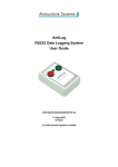
AntiLog
RS232 Data Logging System
User Guide
DOC/ANTILOG/UG/2003001/5.1
25-Mar-2011
G Hatto
(c) Anticyclone Systems Limited
DOC/AntiLog/UG/2003001_5.1
Page 1 of 90
Copyright (c) Anticyclone Systems Ltd, 2011.
All rights reserved.
No reproduction in any form of this publication, in whole or in part
(except for brief quotation in critical articles or reviews),
may be made without prior written authorisation from
Anticyclone Systems Ltd.
Anticyclone Systems Ltd reserves the right to make changes
in the product design without reservation and without notification to its users.
www.anticyclone.co.uk
Disposal of your old product
AntiLog hardware is constructed from high quality materials and components, which can
be recycled and reused. This product is covered by the European Directive 2002/96/EC.
Please inform yourself about the local separate collection system for electrical and
electronic products. Please act according to your local rules and do not dispose of your
AntiLog product with your normal household waste.
DOC/AntiLog/UG/2003001_5.1
Page 2 of 90
Table of Contents
1. Introduction................................................................................................................................................. 7
1.1 Example Application.............................................................................................................................. 7
2. Important Information................................................................................................................................. 8
2.1 User Guide Applicability........................................................................................................................ 8
2.2 Intended Use......................................................................................................................................... 8
2.3 Safety.................................................................................................................................................... 8
2.4 Maintenance......................................................................................................................................... 8
2.5 Recording Considerations..................................................................................................................... 8
2.6 Playback Considerations....................................................................................................................... 9
2.7 Battery Life............................................................................................................................................ 9
2.8 AntiLog Customer Options.................................................................................................................. 10
2.9 AntiLog Design Variants...................................................................................................................... 10
3. Quick Start Guide ................................................................................................................................... 11
4. Getting Started.......................................................................................................................................... 12
4.1 The 'On' and 'Off' Buttons................................................................................................................... 12
4.2 Fitting an Internal Battery.................................................................................................................... 12
4.3 Supplying External Power................................................................................................................... 12
4.4 Switching On for the First Time........................................................................................................... 13
5. The Menu System..................................................................................................................................... 14
5.1 The Main Playback Menu.................................................................................................................... 14
5.2 Playback and Menu Port Reset ......................................................................................................... 15
5.3 Menu System for Dual Serial Port Use................................................................................................ 15
5.4 Locking User Options.......................................................................................................................... 16
5.5 Battery Check...................................................................................................................................... 17
5.6 Turning Your Unit Off.......................................................................................................................... 18
6. Operation Overview.................................................................................................................................. 19
6.1 Recording Channels............................................................................................................................ 19
6.2 Single Serial Port Mode....................................................................................................................... 19
6.2.1 Half duplex bus snooping.......................................................................................................... 20
6.3 Dual Serial Port Mode......................................................................................................................... 20
6.3.1 Dual serial port on the OEM product......................................................................................... 21
6.3.2 Full duplex bus snooping........................................................................................................... 21
6.4 The Recording Mode........................................................................................................................... 22
6.4.1 Terminating a recording session............................................................................................... 22
6.5 Playback Mode.................................................................................................................................... 23
6.5.1 Playback connections............................................................................................................... 23
6.6 Erasing Stored Data Using the Panel Buttons.....................................................................................24
6.7 AntiLog Date and Time....................................................................................................................... 24
6.8 User Equipment Commands............................................................................................................... 25
6.9 Automated Data Recovery.................................................................................................................. 25
6.10 Media Compatibility........................................................................................................................... 26
6.11 Digital Bit State Logging.................................................................................................................... 26
7. General Options Menu.............................................................................................................................. 28
7.1 System Time and Date Options.......................................................................................................... 28
7.1.1 Date and time transfers to other units.......................................................................................29
7.1.2 1PPS time synchronisation output............................................................................................. 30
DOC/AntiLog/UG/2003001_5.1
Page 3 of 90
7.2
7.3
7.4
7.5
7.6
7.7
Menu System Port Settings................................................................................................................. 30
Menu Quiet......................................................................................................................................... 31
Enabling the Dual Serial Port Mode.................................................................................................... 31
Two Button Erase................................................................................................................................ 31
Media Data Recovery......................................................................................................................... 32
User Option Storage........................................................................................................................... 32
7.7.1 Saving a set of user options...................................................................................................... 32
7.7.2 Loading a set of user options.................................................................................................... 33
7.7.3 Erasing a set of user options..................................................................................................... 33
7.8 Power Management and Start Up Options.......................................................................................... 34
7.8.1 Automatic power saving............................................................................................................ 34
7.8.2 Forced playback........................................................................................................................ 34
7.8.3 Forced playback via 'EventIn' line............................................................................................. 35
7.9 AntiLog Software Upgrades................................................................................................................ 35
7.10 Restoring Factory Defaults................................................................................................................ 35
8. Recording Options Menu......................................................................................................................... 37
8.1 Dual Channel Data Logging................................................................................................................ 37
8.2 Configuring a Serial Port for Record.................................................................................................... 38
8.2.1 RS232 signal line inversion....................................................................................................... 38
8.3 Recording Method............................................................................................................................... 39
8.3.1 Recording all data..................................................................................................................... 39
8.3.2 Filtering GPS NMEA messages................................................................................................ 39
8.3.3 Sub Sampling ASCII Line Data................................................................................................. 40
8.3.4 No log method........................................................................................................................... 42
8.4 Time Stamping Recorded Data........................................................................................................... 42
8.4.1 ASCII line time stamping........................................................................................................... 43
8.4.2 ASCII 8 bit line time stamping................................................................................................... 43
8.4.3 'N' byte binary time stamping................................................................................................... 43
8.4.4 Specifying date and time for $EVENT message.......................................................................44
8.5 Defining the End Of Line Character.................................................................................................... 44
8.6 Defining the 'On' and 'Off' button functions for record.........................................................................45
8.6.1 Logging button events............................................................................................................... 46
8.6.2 Logging Digital Bit State on a button push.................................................................................46
8.6.3 Sending User Commands on a button push..............................................................................46
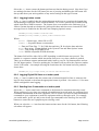
8.7 User Equipment Commands and Polling Functions............................................................................47
8.7.1 Defining the polling period......................................................................................................... 48
8.7.2 Logging Digital Bit State at the polling rate ...............................................................................48
8.8 User Equipment Command Selection................................................................................................. 49
8.9 User Equipment Command Management.......................................................................................... 50
8.9.1 Defining User Equipment Commands.......................................................................................50
8.9.2 Defining User Equipment Commands as hexadecimal.............................................................51
8.9.3 Viewing the current user command definition............................................................................52
8.10 Media Writing Options....................................................................................................................... 53
8.10.1 Ring buffer store..................................................................................................................... 54
8.11 Event input logging............................................................................................................................ 55
8.12 Controlling Front Panel LEDs for Record.......................................................................................... 56
8.13 Erasing Recorded Data..................................................................................................................... 56
8.14 Entering Record Mode from the Menu System..................................................................................56
9. Playback Options Menu............................................................................................................................ 57
9.1 Serial Port Configuration for Playback................................................................................................. 58
9.1.1 RS232 playback signal line inversion........................................................................................ 59
9.2 Raw Playback..................................................................................................................................... 59
9.3 Real Time Playback............................................................................................................................ 59
DOC/AntiLog/UG/2003001_5.1
Page 4 of 90
9.4 Hexadecimal Playback Dump ............................................................................................................ 60
9.4.1 Hexadecimal playback with time stamps...................................................................................61
9.5 Real Time Playback Options............................................................................................................... 61
9.5.1 Maximum playback time delay.................................................................................................. 61
9.5.2 Time shifted playback............................................................................................................... 61
9.5.3 Line triggered playback............................................................................................................. 62
9.6 Session Headers................................................................................................................................. 62
9.7 Time Stamp and Channel Number Playback......................................................................................63
9.7.1 Inserting the channel number into the playback stream............................................................64
9.8 Controlling the Front Panel LEDs for Playback...................................................................................64
9.9 Using the Escape Key to Abort Playback ........................................................................................... 64
10. The About Menu...................................................................................................................................... 66
10.1 Hardware and Software Revisions.................................................................................................... 66
10.2 Detected Capabilities........................................................................................................................ 66
10.3 Port and Settings Overview............................................................................................................... 67
10.3.1 Recording port settings........................................................................................................... 67
10.3.2 Playback port settings............................................................................................................. 68
10.3.3 Menu port settings................................................................................................................... 69
10.3.4 General Menu settings............................................................................................................ 69
11. Baud Rate Selections............................................................................................................................. 70
11.1 Baud Rate Menu Examples............................................................................................................... 70
11.2 User Defined Baud Rate Selection.................................................................................................... 71
12. The AntiLog Data Transfer protocol...................................................................................................... 72
13. RTC Backup Battery .............................................................................................................................. 73
13.1 RTC Battery Backup for AntiLog Hardware.......................................................................................73
13.2 RTC Battery Backup for AntiLogPro Hardware.................................................................................73
14. Problem Solving...................................................................................................................................... 74
14.1 General Problems............................................................................................................................. 74
14.1.1 AntiLog will not switch on........................................................................................................ 74
14.1.2 I can't see the terminal menu in playback mode......................................................................74
14.1.3 I cannot start the unit in record mode......................................................................................75
14.1.4 I see a single red or green flash at start up but nothing else...................................................75
14.1.5 My PC says it wants to install new drivers when I boot up.......................................................75
14.1.6 The unit won't respond to either the 'On' or 'Off' button...........................................................75
14.1.7 The last digit of the current date and time in main menu acts strangely..................................75
14.2 Recording Problems ........................................................................................................................ 76
14.2.1 The data I logged appears corrupted......................................................................................76
14.2.2 I see three or four flashing red LEDs in recording mode ........................................................76
14.2.3 I see five flashing red LEDs in recording mode ......................................................................76
14.3 Playback Problems........................................................................................................................... 77
14.3.1 The output 'breaks up' on my terminal screen during playback. ............................................77
14.3.2 I can't stop the playback once it has started............................................................................77
14.3.3 I have started playback but nothing is coming out...................................................................77
15. Abbreviations.......................................................................................................................................... 78
16. Appendix A – Standard Feature Set....................................................................................................... 79
16.1 AntiLog Standard Feature Set........................................................................................................... 79
16.1.1 General features..................................................................................................................... 79
16.1.2 Recording features.................................................................................................................. 79
16.1.3 Playback features.................................................................................................................... 79
16.1.4 Configuration features............................................................................................................. 79
16.2 Feature Set for AntiLog Hardware REV C and Later.........................................................................80
16.3 Feature Set for AntiLog Hardware REV E and Later.........................................................................80
16.4 Feature Set for AntiLog Hardware REV F and Later.........................................................................80
16.5 AntiLogPro specific features.............................................................................................................. 80
DOC/AntiLog/UG/2003001_5.1
Page 5 of 90
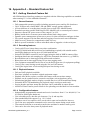
17. Appendix B – Option Packs................................................................................................................... 81
17.1 Option Pack Codes........................................................................................................................... 81
17.2 Software Options............................................................................................................................... 81
17.2.1 'D' Option – Force Dual Serial Port Operation.........................................................................81
17.2.2 'L' Option – Menu Port lock..................................................................................................... 81
17.2.3 'M' Option – ICD-GPS-15x...................................................................................................... 82
17.2.4 'N' Option – NOLOG................................................................................................................ 82
17.2.5 'S' Option – Security (password controlled menu access).......................................................83
17.2.6 'X' Option – Extended Playback 'On' delay..............................................................................83
17.3 Hardware Options............................................................................................................................. 83
17.3.1 'P' Option – Forced Power....................................................................................................... 83
17.3.2 'R' Option – OEM Real Time Clock......................................................................................... 83
17.3.3 '[R]' Option – External Real Time Clock..................................................................................83
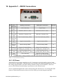
18. Appendix C – RS232 Connections......................................................................................................... 85
18.1 DC Power.......................................................................................................................................... 85
18.2 Dual Serial Port Cable....................................................................................................................... 86
18.3 Dual Port Data Sniffing Cable........................................................................................................... 86
19. Appendix D – LED Flash Codes............................................................................................................. 87
19.1 Recording Errors............................................................................................................................... 87
19.2 Recording Modes.............................................................................................................................. 87
19.3 Playback Modes................................................................................................................................ 87
19.4 Playback Error Codes....................................................................................................................... 88
19.5 LEDs During Media Data Recovery................................................................................................... 88
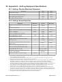
20. Appendix E – AntiLog Equipment Specifications.................................................................................89
20.1 AntiLog: Absolute Maximum Parameters.......................................................................................... 89
20.2 AntiLog: Normal Operation................................................................................................................ 89
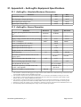
21. Appendix E – AntiLogPro Equipment Specifications...........................................................................90
21.1 AntiLogPro: Absolute Maximum Parameters.....................................................................................90
21.2 AntiLogPro: Normal Operation.......................................................................................................... 90
Index of Figures
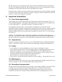
Figure 1: AntiLog............................................................................................................................................. 10
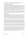
Figure 2: AntiLogPro....................................................................................................................................... 10
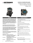
Figure 3: Battery access.................................................................................................................................. 12
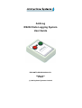
Figure 4: Single port recording configuration .................................................................................................. 19
Figure 5: Single port playback configuration.................................................................................................... 20
Figure 6: Example of single port bus snooping............................................................................................... 20
Figure 7: Recording from two data sources simultaneously............................................................................21
Figure 8: Example dual serial port configuration............................................................................................. 21
Figure 9: Example of dual port bus snooping.................................................................................................. 22
Figure 10: Playback configuration................................................................................................................... 24
Figure 11: Dual serial port playback................................................................................................................ 24
Figure 12: Ring buffer block filling during record............................................................................................. 54
Figure 13: Dual serial port cable wiring........................................................................................................... 86
Figure 14: Dual port data sniffing cable wiring................................................................................................. 86
DOC/AntiLog/UG/2003001_5.1
Page 6 of 90
1. Introduction
The AntiLog range of products from Anticyclone Systems Ltd provide a very effective way to
log RS232 data from a vast range of civil and military products including GPS navigation
receivers, laboratory and medical equipment, process control systems and sensor units (e.g.
temperature, weight, inertial). There are boxed versions of the product which can operate
stand alone and there are OEM versions which allow you to easily add a data logging solution
to your own equipment configurations. All versions of the product can be fed with an external
DC power source for extended operation.
The design goal was to establish an incredibly simple to operate RS232 data logging system
that only required two panel mounted buttons - 'On' and 'Off'. Even though AntiLog units are
simple to operate, there are no compromises on features available or on performance. Each
AntiLog unit contains an embedded microcontroller which is able to perform full speed real
time capture of RS232 data without any hold off (e.g. flow control) which could upset the
timing of equipment under investigation.
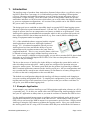
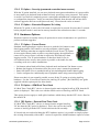
V5.1 of the embedded software supports both the original
AntiLog hardware and the new AntiLogPro hardware
design. V5.1 is backward compatible with all previous
AntiLog board revisions and has the ability to log two
independent serial port data streams at the same time on
supported hardware. This is a very powerful feature which can
be likened to having two single channel AntiLog units in one
box. As an example, with dual serial port logging, you are able to monitor RS232 data in both
directions on an existing full duplex RS232 link, even if the two data paths have different
baud rates and port settings.
The key to the success of AntiLog lies in the ability to configure the system before trials or
other recording sessions take place. AntiLog units are configured for operation using an
interactive menu system. The menu system built into the product is operated by a standard
RS232 terminal application connected to the AntiLog serial port. All user configurations and
any recorded data are stored in non-volatile memory so flat batteries or battery changes have
no effect on the unit's configuration or the recorded data.
The default user configuration shipped with AntiLog will almost certainly need changing to
suit your recording and playback needs. To simplify unit configuration, you are able to group
together and store up to four named sets of user options so that you can later recall these in
one go for your different data logging trials.
1.1 Example Application
As an example, you could use AntiLog to test GPS navigation application software on a PC in
a repeatable way. To do this, you would collect real GPS data using AntiLog and play it back
into your PC application as many times as you want in real time to simulate the GPS receiver.
Use the AntiLog terminal menu system to configure real time playback and to set the record
and playback baud rates to be the same as the GPS receiver. Then connect AntiLog to the
GPS receiver and record the NMEA output for a representative period of time. Simply switch
AntiLog off using the 'Off' button to terminate the logging session. Next, you would connect
the AntiLog unit to the PC using a NULL modem cable and press and hold the 'On' button so
DOC/AntiLog/UG/2003001_5.1
Page 7 of 90
that the unit powers up in playback mode. Stop and start the playback of the recorded data
into your PC application using 'On' and 'Off' button presses or even restart playback from the
beginning of the log data at any time just by pressing the 'On' button.
Note that in this example, once the terminal menu system has been used to configure AntiLog,
no further contact with a host machine is required. Simply use the unit with the 'On' and 'Off'
buttons to conduct data logging and playback.
2. Important Information
2.1 User Guide Applicability
This manual refers to AntiLog products from Anticyclone Systems Ltd running release V5.1
of the embedded software. All original AntiLog hardware release revisions are supported up
to and including REV F. AntiLogPro hardware is supported at REV A.
The embedded software release version number and hardware revision codes can be
determined from the playback terminal menu system described in section 10 of this document.
Separate supplement guides are available for the OEM versions of the product and for the
additional option packs which extend AntiLog capability for specific users. For more details,
see section 17.
AntiLog V5.1 embedded software is therefore available for all existing AntiLog hardware
revisions. Note that some of the earlier AntiLog hardware may not be able to support some of
the latest features (for example, not all older hardware supports the dual serial port feature).
2.2 Intended Use
AntiLog is intended exclusively for use as a low voltage RS232 data recording and playback
system. Anticyclone Systems Ltd is not liable for any damage resulting from improper use.
2.3 Safety
• Avoid exposure to extreme humidity (e.g. do not spray or submerge in water).
• Never apply more than 18.0V to the DC supply input to avoid damage and always ensure
mains power adapters are safe, correctly insulated and correctly earthed before use.
• Ensure the equipment to be connected to your AntiLog unit is correctly earthed and does
not apply power in any form to the RS232 signal connections.
• Do not expose the AntiLog enclosure to any solvents.
• Do not store or operate this product within the reach of children – this product is not a toy!
2.4 Maintenance
Clean boxed AntiLog units with a dry cotton cloth which should be slightly moistened in case
of heavy staining. Never use cleaning agents which contain solvents.
2.5 Recording Considerations
Always select the correct RS232 baud rate and the correct number of RS232 data bits for data
recording. Any data collected using AntiLog where there is a difference between the
recording baud rates and/or the number of data bits per character may result in severely
corrupted or lost data. In common with any other RS232 data recording system, it is not
DOC/AntiLog/UG/2003001_5.1
Page 8 of 90
normally possible to recover any information from data recorded at the wrong baud rate or
data recorded with the wrong number of RS232 data bits per character.
2.6 Playback Considerations
The playback baud rates are completely independent of the baud rates you used to record the
data. You may select any combination of baud rate and RS232 bits per character which suit
your needs. However, If you attempt to use a terminal program to view the AntiLog playback
menu system you may see nothing if the terminal baud rate and/or data bit selection is
different to the currently set AntiLog menu baud rate. Section 5.2 describes how to reset the
menu port settings to a known state if this happens. Additionally, if you have hardware that
supports the Dual Serial Port feature, playback and/or the menu system may be assigned to
different hardware serial ports and so output may not be seen on the primary port.
Also note that if you choose to playback data with less RS232 bits per data character than the
recorded data format, data corruption may occur if any of the output bytes don't fit into the bits
specified. The safest policy is to leave the number of RS232 bits per character set to eight for
playback and for the menu system unless your host equipment requires other settings.
2.7 Battery Life
If you are running from an internal battery, always use a new one when recording important
trials data. To maintain the life of the battery, it is recommended that it is disconnected
completely from the system if AntiLog is not to be used for more than a week or so. This is
because AntiLog supports active power management which means that there is a very small
current drain on the battery when AntiLog is switched off. Over extended periods of time,
this standby current will effect the total charge remaining in a given battery. Use the battery
check feature at the main playback terminal menu to ensure the battery is in good condition.
If you do not need to transmit to your unit in record mode (e.g. you are not transmitting
polling or other equipment initialisation requests) then you can save power by not physically
connecting the transmit pin from AntiLog. This power saving tip works because AntiLog
must drive the fixed load in the equipment if this connection is made which will consume a
small amount of power. Note that AntiLogPro hardware automatically performs this function
for you internally without the need to disconnect any signal wires from the connecting cable.
When AntiLog is idle, it will consume less power when running V5.1. Typically, AntiLog can
reduce the running power consumption by 25% compared to the original single channel build
of AntiLog software. If your data source has data gaps (such as during GPS NMEA sentence
transmission) then you will observe lower power consumption compared to full rate data.
For the original AntiLog boxed units fitted with the Real Time Clock (RTC) feature (hardware
REV F and above, and RTC upgrades), there is a backup battery fitted to the upper PCB card
mounted in the lid section of the unit which may need replacing after several years use. A
warning will be displayed via the terminal menu system if an RTC power failure has been
detected. Replacing this battery will require screwdriver access to remove the lid assembly. In
the AntiLogPro design, there is a rechargeable Lithium battery inserted into a holder on the
main PCB so that the battery can be replaced should it fail to hold charge.
DOC/AntiLog/UG/2003001_5.1
Page 9 of 90
2.8 AntiLog Customer Options
The standard hardware and embedded software provide a core level of functionality that is
designed to meet the vast majority of customer data logging needs. Section 16 gives a
complete list of features that apply to the various hardware revisions. For each AntiLog build
type, there are two available variants, boxed and OEM.
For specific customers, extra software and hardware options are available in the form of
option packs. Option packs simply extend the capability of the standard AntiLog product.
For example, the 'M' option pack provides effective logging of serial data from Military or
Government GPS receivers. See section 17 for a summary of the option packs available.
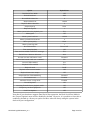
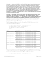
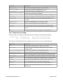
2.9 AntiLog Design Variants
The following table describes the main capability differences between the AntiLog hardware
design build variants when running V5.1 of the embedded software.
Capability
AntiLog
AntiLogPro
2
3
Maximum supported baud rate (each channel)
460800
921600
Maximum full rate single channel data logging (baud)
230400
921600
Maximum full rate dual channel data logging (baud per channel)
115200
460800
Pins that can be used as logged digital inputs
5
8
Bi-colour LED state indicators
1
2
User invertible RS232 lines (e.g. for CMOS level logging)
N
Y
Selectable “ring buffer” storage method
N
Y
Battery test voltage indicator (maximum)
9.9V
20.0V
N
Y
Number of hardware serial ports supported
One Pulse Per Second (1PPS) output time stamp reference (OEM only)
Figure 1: AntiLog
DOC/AntiLog/UG/2003001_5.1
Figure 2: AntiLogPro
Page 10 of 90
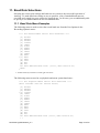
3. Quick Start Guide
When you first receive your AntiLog unit, you will want to check that it functions correctly.
You may also want to change the settings from the factory defaults. The following very top
level description will allow you to connect AntiLog to a PC, power it up for the first time, turn
it off, turn it back on in record mode and turn it off again. For more details on all of these
actions, see the rest of the user guide.
• Connect a NULL modem 9 way D cable (one is supplied with boxed AntiLog) between the
AntiLog unit and a PC.
• Configure a terminal program of your choice (such as Microsoft HyperTerminal) on the PC
to 115200 baud, 8 bits, no parity with handshaking set to 'none'.
• Fit a battery to AntiLog or connect a regulated 4.5V to 18V (maximum) to the DC power
jack, centre pin +ve.
• Switch on AntiLog in playback mode by holding down the 'On' button until a green LED
lights, then release.
• Terminal should now show the main menu (use terminal space bar to refresh the display).
AntiLog-MR V5.1, Serial number ASL/16/001, 28-Feb-2011 15:20:03.519
(32430 bytes recorded in 1 session, 0% of 489.2MB)
(PLAYBACK mode. Data transfer and 'On' button aware)
<S>
<R>
<P>
<G>
<L>
<B>
<A>
<U>
?
Start playback now (or use 'On' button)
Recording options
Playback options
General options
Lock user options
Battery check
About AntiLog
Shut down
• Use terminal keyboard input to select menu items and change AntiLog settings.
• To turn AntiLog off, hold the 'Off' button down for more than 1 second. You should see
both LED colours flash briefly to confirm power down, then release.
• To turn AntiLog on in record mode, simply press the 'On' button for a short period (i.e. less
than 1¾ seconds), LED will flash red. Note that LED will flash red followed by a number
of green (and/or yellow) flashes to show you AntiLog is writing data to FLASH store in
record mode.
• To turn AntiLog off again, hold 'Off' button down for more than 1 second, wait for LED
confirmation, then release.
DOC/AntiLog/UG/2003001_5.1
Page 11 of 90
4. Getting Started
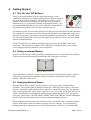
4.1 The 'On' and 'Off' Buttons
There are two push buttons and one (AntiLog hardware) or two
(AntiLogPro hardware) bi-coloured, high intensity LEDs mounted on
the front panel of the boxed units. The buttons are sensitive to the
amount of time they are held down to allow the unit to operate in
different ways (e.g. to start the recording and playback modes). The
green push button labelled 'On' is used to switch the unit on and the
red push button labelled 'Off' is used to switch the unit off.
The buttons can also be used when AntiLog is already powered on to perform other functions.
For example, the 'On' button can be used to start the playback of recorded data or log events
and send selected user commands to connected equipment in record mode. The 'Off' button
can stop data playback and can also be used in the record mode for selected event recording
and user command output.
All that is required to get AntiLog working is a power source and an RS232 data cable
connection. The main power source can be a PP3 battery fitted internally, or an external
source plugged into the external DC power connector.
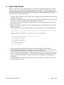
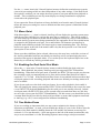
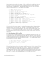
4.2 Fitting an Internal Battery
To fit a new PP3 battery, remove the battery compartment cover on the back of the AntiLog
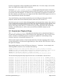
enclosure by pressing down on the marked area and sliding the cover back.
Figure 3: Battery access
Fit the PP3 battery to the PP3 flying lead clip inside observing the polarity of the connector.
Note that it is not possible to damage AntiLog by making a connection with the wrong
polarity. Refit the battery cover.
4.3 Supplying External Power
External power can be fed into AntiLog units via a DC power jack to extend normal
operation. The original AntiLog hardware requires a 6.5mm DC power jack (2.1 mm inner
pin size) connection. AntiLogPro hardware requires a 1.3mm DC power jack. All AntiLog
units accept regulated DC power in the range 4.5 to 18V (9.5 to 18V for the Forced Power 'P'
option) which means for example that AntiLog can be fed directly from a 12V car battery
source for vehicle trials. NEVER APPLY MORE THAN 20V ABSOLUTE MAXIMUIM to
the DC feed at any time otherwise you may permanently damage your unit.
When supplying external power, the centre pin of the external DC power connector must be
positive with respect to the outer barrel to supply power to AntiLog. It is not possible to
damage AntiLog by applying power with the wrong polarity. However, if an internal PP3
DOC/AntiLog/UG/2003001_5.1
Page 12 of 90
battery is fitted, the power will be taken from this instead of the external source and hence the
system may give the impression of being powered externally, but will stop logging when the
internal battery runs out.
AntiLog gets its power from either the internal battery connection or from an external power
source. If an internal battery is fitted then the external power source MUST have a higher
voltage than the terminal voltage of the battery fitted, otherwise the external DC power source
will be ignored and instead, power will be taken from the internal battery. For this reason, it is
recommended that the external DC voltage should be 10V to 18V if an internal PP3 is already
fitted.
Anticyclone Systems Ltd recommend fitting an internal battery if you are supplying an
external power source higher than 9V because if for some reason the external supply of power
to the AntiLog unit is interrupted for a short time (e.g. a car adapter gets knocked or vibrated
out of position during a car trial) then the internal battery power source will automatically take
over and cover for the drop out period.
The external DC power source will never attempt to charge any internally fitted cell. If you do
fit a PP3 rechargeable cell into AntiLog, this is OK, but it must be removed from the unit and
recharged separately when required.
4.4 Switching On for the First Time.
Connect your AntiLog unit to a PC using a NULL modem cable (the cable is supplied with the
boxed version of the product). Configure a terminal port application (such as Microsoft
HyperTerminal) to 115200 baud, 8 bits no parity with no flow control.
Press and hold the 'On' button until the green LED lights (top LED for AntiLogPro hardware)
to enter the playback mode and release. You have now started AntiLog in the playback mode
(LED will flash green) and the text based menu system will appear on the terminal screen.
DOC/AntiLog/UG/2003001_5.1
Page 13 of 90
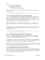
5. The Menu System
5.1 The Main Playback Menu
The playback main menu will appear each time the unit is powered on in playback mode1.
The default serial port settings for the playback menu system are 115200 baud, 8 bits, no
parity, one stop bit. The menu system allows you to quickly change recording, playback and
system settings within AntiLog. All settings are non-volatile which means that they will
remain active even if all sources of power are removed.
A display is shown for each menu and single keys are typed into the terminal to select
different menu options. Keyboard selections available are enclosed in either angled (<>) or
square ([]) brackets. If a menu item is shown in angle brackets, it means that a sub menu or
other prompt or action will follow this menu item if selected, else square bracketed items
show that an item is selectable directly on the page. A '*' character next to a menu item
indicates that item is active or selected. Text within menus which appears in between curly
brackets, '{' and '}', indicate a currently active value for a selectable item.
The terminal keyboard 'Escape' key is used to abort operations and to exit sub menus. For
some special sub menu functions, the 'On' or 'Off' buttons must be used to confirm or reject
user input. The current menu content can generally be refreshed to the terminal by typing the
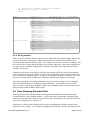
terminal space bar at any time. The following is an example of an AntiLog main menu:AntiLog-[R] V5.1, Serial number ASL/16/001, 25-Feb-2011 12:09:10.234
(Ch1=602475, Ch2=2113535 bytes recorded in 2 sessions, 1% of 244.7MB)
(PLAYBACK mode. Data transfer and 'On' button aware)
<S>
<R>
<P>
<G>
<L>
<B>
<A>
<U>
?
Start playback now (or use 'On' button)
Recording options
Playback options
General options
Lock user options
Battery check
About AntiLog
Shut down
The first line starts with the product name (e.g. AntiLog or AntiLogPro ). If the name is
followed by _OEM (e.g. AntiLogPro_OEM ) then the software is running on OEM hardware
and extra features will be enabled later in the menu system to allow access to the extended
features in the OEM version of the product.
The product name is followed by a dash and any options you have installed. In the example,
[R] means the AntiLog hardware real time clock is present. Following on this line is the
embedded software version number, a unique product serial number and the current date and
time (if available).
The next line shows how many bytes (characters) are currently recorded (both channels when
applicable) to the flash media store, how many sessions have been recorded and how full the
store currently is (as a percentage) and the total data storage capacity of the installed media in
MB (Megabytes) or GB (Gigabytes), whichever is appropriate.
1 Selecting the 'Menu Quiet' item in the 'General' menu will inhibit this output if desired.
DOC/AntiLog/UG/2003001_5.1
Page 14 of 90
The next line shows that AntiLog is in playback mode and it is ready for special AntiLog
specific 'Data Transfers' upon request, and it will start transmitting data from the start of the
store as soon as the 'On' button is pressed.
The items in the main menu allow you to enter the recording menu, playback menu and a
general options menu (which covers system wide selections). The other items allow you to
start playing back data now (equivalent to pressing the 'On' button on the front panel), lock the
user options (to prevent accidental modification to the settings in trials), check the battery
status and to show more about the current settings, detected capabilities and embedded
software details. You can also request a system power shut down (equivalent to holding the
'Off' button) form the main menu.
The 'About AntiLog' menu item is an important option which allows you to see a summary of
AntiLog's settings, detected options, user selections and current hardware configuration. We
recommend you use this feature frequently to check your settings before you commit to
recording important data in a trials environment. The about menu feature is described in more
detail later in section 10.
5.2 Playback and Menu Port Reset
The playback and menu port settings can be set via the terminal menu system to a wide range
of combinations. If the Dual Serial Port option is enabled in the 'General options' menu, then
the playback and menu systems can additionally be configured to operate on either the main or
the secondary serial port. The default is to use the primary serial port for both the playback
and menu system.
If you change the menu or playback port settings and forget what you have set them to (or you
suspect someone else has altered the port settings without your knowledge) then there is a
simple way to return the playback and menu port settings back to known conditions. With
AntiLog switched off, press and hold the 'On' button for at least ten seconds until the LED
(top LED for AntiLogPro) turns solid yellow (both red and green segments light up). Release
the 'On' button and this will force the playback and menu port settings to the factory defaults.
AntiLog will enter playback mode with a flashing green LED. The terminal menu system will
be set to the primary serial port with a baud rate of 115200, eight bits per character, no parity
and one stop bit. No other settings (e.g. record port settings, playback modes, etc.) are
modified during this process and all recorded data is preserved.
5.3 Menu System for Dual Serial Port Use
When dual serial port operation is selected in the 'General Options' menu, dual port recording
and/or dual serial port playback can be selected in the 'Recording Options' and the 'Playback
Options' menu respectively. In this case, the menu system will always show which channel
the current menu refers to when the content is channel specific. To help with the definition of
dual port features, you are able to quickly switch backward and forward between the channel
settings at various menu levels. In some menus, you are also able to copy the settings from
one channel to another at the current menu level to speed up unit configuration.
As an example, most channel specific menus have one or more of the following options
present:-
DOC/AntiLog/UG/2003001_5.1
Page 15 of 90
[G] Go to the other channel
[+] Copy these options to the other channel
Use the <G> item to flick between channel 1 and channel 2 settings at the same menu level.
Use the '+' item to copy these settings to the other channel. You will be prompted to confirm
this action before the copy actually takes place. Note that the copy is intelligent in that if you
copy port settings from one channel to the other, it ensures both ports are not assigned to the
same physical serial port hardware.
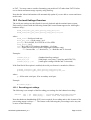
5.4 Locking User Options
The user is able to change the recording, playback and general options with simple key presses
using the terminal menu system in playback mode. However, if AntiLog is accidentally
connected to a live source of RS232 data and the unit is powered on in playback mode instead
of the intended recording mode, AntiLog will think the incoming characters are user menu
input and settings may be altered. If the incoming input stream just happens to have the
characters 'REY' at the point when AntiLog is at the root menu, then AntiLog will go into the
recording options (<R>), select 'Erase all recorded data' (<E>) and will confirm deletion ('Y').
The user options lock prevents any input in playback mode from altering any of the AntiLog
system settings. For this reason, Anticyclone Systems Ltd strongly recommends always using
the settings lock feature to protect the settings on your AntiLog unit. It does not stop the unit
functioning in playback mode, it just prevents any alteration to the data and/or user settings.
Enabling the lock has been made very easy. Simply type an 'L' key at the root menu and the
main menu will change as in the example that follows:AntiLog-[R] V5.1, Serial number ASL/16/nnn, 28-Feb-2011 12:33:53.042
(3148395 bytes recorded in 1 session, 9% of 30.3MB)
(PLAYBACK mode, Data transfer and 'On' button aware)
<S> Start playback now (or use 'On' button)
!LOCKED! Recording options
!LOCKED! Playback options
!LOCKED! General options
<L> UnLock user options
<B> Battery check
<A> About AntiLog
<U> Shut down
?
It is now only possible to start data playback (which is always a non destructive action),
attempt to unlock the options lock (discussed here later), display more about AntiLog (read
only) or to safely shut the system down. Attempts to select other menu items are ignored.
To unlock the options lock, you need to go through a set sequence. With the root menu
locked, type 'L' and confirm that you want to release the options lock by typing a 'Y' key at the
'Are you sure?' prompt. The following display shows the screen output to this stage:-
DOC/AntiLog/UG/2003001_5.1
Page 16 of 90
Are you sure?
<Y> Yes
<N> No
<Esc>
? Y
==== Unlock User Options ====
**** Press the 'On' button now to unlock user options ****
?
Escape key or 'Off' button to cancel the operation
<Esc>
At this moment in time the options lock is STILL active. Press the main green 'On' button to
actually release the lock. If instead you press the 'Off' button at this point the operation is
cancelled and the options lock will remain on. If you type a space character, RETURN or
LINEFEED character then the display is refreshed waiting for the 'On' key once more but no
other actions are taken. Any other keyboard input will cancel the unlock operation and the
options lock will remain on.
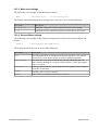
5.5 Battery Check
A battery check will show the current condition of the AntiLog power source. The testing is
performed against the current power supply input which is either through the external DC
socket or via the internal PP3 clip connection. Note that if a PP3 battery is fitted but an
external power source is simultaneously applied with a terminal voltage higher than the PP3
voltage, then the test results will relate to the external power source, not the PP3 battery.
Select the <B> item at the AntiLog main menu to show the battery condition check menu.
==== Battery Condition Check ====
If power goes off during a check then battery needs replacing.
A check will take approximately 20 seconds to complete.
?
<B> Start a battery condition check
<Esc>
Select the <B> item in the 'Battery Condition Check' menu to actually perform a battery check.
During the check, a number of '#' characters are filled into a bar style display as shown below.
When all of the '#' characters have been drawn (which will take no more than about 20
seconds), the test results are shown. An example of a typical battery condition check follows.
Performing battery condition check
[####################]
***
***
***
***
***
Test Results:Battery voltage, min load = 9.0V
Battery voltage, max load = 8.9V
ADVISE: More than 24 hours remaining
Testing complete
If the bar display appears to lock up (i.e. The display is not completed within about 20
seconds) then the check detected that the supply had fallen below an internal cut-off voltage
DOC/AntiLog/UG/2003001_5.1
Page 17 of 90
limit and the unit has automatically shut down. This action indicates the the source battery
needs replacing immediately.
You may terminate a battery check when it is running at any time by pressing the 'Off' button.
In this case, the battery test will be aborted and no test results are reported.
5.6 Turning Your Unit Off
To turn off AntiLog at any time, press and hold the 'Off' button for more than one second until
you see red and green LED segments light up simultaneously for a brief period indicating the
shut down request has been actioned, and then release the 'Off' button. It is not possible to
turn off the unit by briefly touching the 'Off' button. This feature helps prevent accidental shut
down incidents which could be caused by knocking into the buttons in a trials environment.
However, you are also able to shut down AntiLog from the main menu. Select the <U> item
at the main menu and AntiLog will ask you confirm the action:Shut down...
Are you sure?
?
<Y> Yes
<N> No
<Esc>
Type a 'Y' key to proceed with the shut down or an 'N' key (or any other key other than the
space bar which will just refresh the display) to cancel the request.
DOC/AntiLog/UG/2003001_5.1
Page 18 of 90
6. Operation Overview
6.1 Recording Channels
There are two recording channels built into AntiLog V5.1. If you configure your unit for dual
serial port operation you can think of each channel as being a separate single channel AntiLog
unit. Therefore, each channel can be completely independently configured for use and each
has its own hardware serial port connection. For single serial port operation, all recording and
playback is performed on channel 1. By default, channel 1 is assigned to the primary serial
port and channel 2 is assigned to the secondary serial port hardware but you can choose to
swap them over if you wish using the AntiLog terminal menu system.
For AntiLogPro OEM hardware, you can choose from three hardware serial port sources for
each logging channel. The primary serial port, the secondary serial port and a third CMOS
level auxiliary serial port available from the internal J3 pin header.
Each channel can define its own response to 'On' and 'Off' button pushes whilst in the
recording mode. You can assign equipment user commands and log events from button
pushes during the record mode. Each channel has its own independent polling mechanisms
which can even output messages on the other channel output port if required. You can for
example easily log selected GPS NMEA sentences on one channel and poll a radio frequency
power meter for readings at a user defined rate whilst recording its output on another.
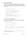
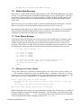
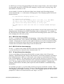
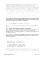
6.2 Single Serial Port Mode
With the standard single serial port configuration you must perform all serial port activities
through the one primary hardware serial port. For example, this means you will need to
disconnect the recording data source from the AntiLog serial port connector to plug in a
NULL modem cable or equivalent for data replay into a host computer such as a PC. You are
also only able to record or play back into a single RS232 connection.
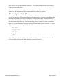
When recording data in single channel mode, AntiLog is designed to look like a PC COM port
so that equipment designed to plug into the serial port of a PC will plug straight into AntiLog
without any need for additional cabling.
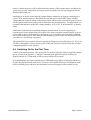
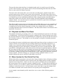
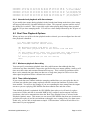
RS232 data source.
E.g. GPS receiver.
1:1 RS232 cable
AntiLog
Figure 4: Single port recording configuration
If the cable connecting the equipment to AntiLog is incorrect or the baud rate specified within
AntiLog does not exactly match that of the source data, then successful recording will not be
possible.
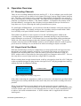
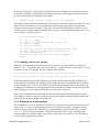
When playing back data in single channel mode, the connection appears as though it is
coming from a PC. To connect AntiLog to a real PC therefore requires a NULL modem cable.
A NULL modem cable crosses over the transmit and receive lines as well as handshake lines
to achieve successful communications. A NULL modem cable is supplied with a boxed
AntiLog unit.
DOC/AntiLog/UG/2003001_5.1
Page 19 of 90
PC, PDA or other
RS232 host
RS232 NULL modem cable
AntiLog
Figure 5: Single port playback configuration
If the cable is not correct, or the host machine (e.g. a PC) is not configured to the baud rate
and data bits which exactly matching the AntiLog settings then successful communication will
not be possible.
If the Dual Serial Port mode is not active or it has been deselected, then the RTS/CTS line
functionality is available in the playback menu options. If dual serial port mode is enabled,
the RTS/CTS lines become the secondary serial port transmit and receive lines.
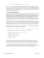
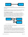
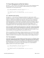
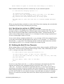
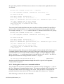
6.2.1 Half duplex bus snooping.
In single serial port mode you can 'listen in' to one of the lines on an existing RS232
connection without upsetting the data flow because AntiLog does not require any form of
handshaking to slow down the data source. To listen to a single line on an existing
connection, you need a connection from the primary AntiLog Receive Data (Rx1) line and
ground (GND) to the cable RS232 signal line of interest (normally pin 2 or 3 on the
equipment connector depending on whether you want to listen in to the Transmit or the
Receive line) and Ground. See section 18 for AntiLog connector wiring details.
Transmit
User Equipment 1
Receive
User Equipment 2
Ground
Rx1
Gnd
AntiLog
Figure 6: Example of single port bus snooping
A half duplex bus snooping adapter cable is available from your local AntiLog supplier if you
do not want to construct a cable for your own application.
6.3 Dual Serial Port Mode
If you have hardware revision C or later, you may select the Dual Serial Port operating mode.
In Dual Serial Port mode, AntiLog is able to use the primary serial port and an additional
secondary serial port for all data recording, playback and terminal menu system activities. A
special 'V' or 'Y' shaped lead is used to plug into the single AntiLog 9 way D connector to give
two 9 way D connections, each of which look like PC serial ports to connected equipment.
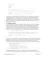
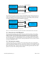
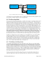
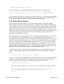
If you need to log the output from two pieces of equipment at the same time, you can use the
following configuration. Note the data paths below are shown bi-directional because you can
independently transmit user commands as well as receive data from the two serial ports.
DOC/AntiLog/UG/2003001_5.1
Page 20 of 90
RS232 data source.
E.g. GPS receiver.
1:1 RS232 cable
Primary serial port
'Y' Lead
RS232 data source
E.g. Power Meter
AntiLog
1:1 RS232 cable
Secondary serial port
Figure 7: Recording from two data sources simultaneously
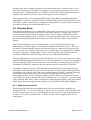
The terminal menu system is used to configure independently which AntiLog serial ports are
used for record, playback and for the terminal menu itself. The ability to assign which port is
used for the different serial port functions greatly increases the flexibility of the system and
can simplify installation in completely standalone installations.
RS232 data source.
E.g. GPS receiver.
PC, PDA or other
RS232 host
1:1 RS232 cable
RS232 NULL
modem cable
Primary serial port
'Y' Lead
AntiLog
Secondary serial port
Figure 8: Example dual serial port configuration
The 'V' or 'Y' lead is also used if you need to play back on both channels at the same time.
6.3.1 Dual serial port on the OEM product
The boxed AntiLog product requires RS232 line levels on both the primary and secondary
ports to function. The OEM designs allow a configuration to provide a direct connection to
CMOS 3V3 RS232 levels (on the secondary and auxiliary serial ports only) when in dual
serial port mode. This allows data logging from direct connections to OEM equipment that
does not contain RS232 level shifting hardware (such as most OEM GPS receiver modules).
See the OEM supplement supplied with the AntiLog OEM product for more details on how to
access the CMOS RS232 levels.
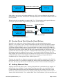
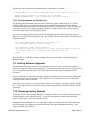
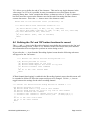
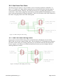
6.3.2 Full duplex bus snooping.
In dual serial port mode you can 'listen in' and record both data paths on an existing RS232
connection without upsetting the data flow. You need to connect one of the signal lines to the
primary AntiLog Receive Data (Rx1) input and the other signal line to the secondary AntiLog
Receive Data (Rx2) input. You also need to connect the AntiLog ground (Gnd) to the cable
ground. See section 18 for AntiLog connector details.
DOC/AntiLog/UG/2003001_5.1
Page 21 of 90
Transmit
User Equipment 1
Receive
User Equipment 2
Ground
Rx1
Rx2
Gnd
AntiLog
Figure 9: Example of dual port bus snooping
A full duplex bus snooping adapter cable is available from your local AntiLog supplier if you
do not want to construct a cable for your own application.
6.4 The Recording Mode
If you press the 'On' button momentarily (i.e. hold it for less than 1¾ seconds) when the unit is
powered down then the unit will switch on and enter the recording mode. The bi-coloured
LED (lower LED on AntiLogPro hardware) will light red for a second or so and then flash red
to show the unit is in recording mode. The unit is now recording any data seen on the 9 way
D connector using your selected recording method. For the original AntiLog hardware, you
will know if data is being written to the flash store because the panel LED will flashes once in
red and then flash one or more times (depending on the data filtering currently selected, see
section 19.2) in green and then yellow to represent the two recording channels followed by a
pause. If no new data is being written to the flash store, only a single red flash is seen. For
AntiLogPro hardware, the top LED flashes green after the lower LED red record flash to show
data is being recorded for channel 1 and the lower LED flashes green when data is being
recorded for channel 2. The number of green (or yellow for original AntiLog) LED flashes
that immediately follow the red flash indicate the data filtering mode active during record.
If AntiLog is configured to record everything it sees on the RS232 port, one coloured flash
will appear when data is present for a given channel. If AntiLog is configured to filter
incoming NMEA sentences, then two LED flashes will be seen when data accepted by the
filter is written to the flash media store. If the ASCII line sub sample filter is enabled, then
four LED flashes will be seen when the accepted filtered data is written to the flash media
store. To see a table of these flash codes, see section 19.2.
6.4.1 Terminating a recording session
To terminate a data logging session, the 'Off' button is used. However, you cannot simply
press the 'Off' button momentarily to turn the unit off, you must hold it down for at least one
second to terminate the logging and to turn the power off. This feature helps to reduce the
incidence of data recording loss due to accidental activation of the 'Off' button by knocking it
during trials and it also allows user events to be logged using a normal momentary push of the
'Off' button during the record process. When you do attempt to terminate a logging session,
you will see both red and green LED segments light up simultaneously for a brief period
indicating the shut down request has been actioned.
You may repeat the 'On' and 'Off' cycling of the power in record mode as many times as
required to append more data to the AntiLog media store without the fear of losing data
DOC/AntiLog/UG/2003001_5.1
Page 22 of 90
already stored. Data is simply appended to the current media store in a new session. Every
time you switch the unit on and start recording more data, AntiLog will create a new time
stamped session. During playback, it is possible to embed this session information into the
playback data stream so you know when each logging session commenced.
If the storage media is ever completely filled (and the Ring Buffer recording method and
AntiLogPro is not active), the unit will stop recording and the panel LED will flash five times
followed by a pause, continuously. It is therefore not possible to overwrite (and hence delete)
recorded data with any new data at the RS232 port.
6.5 Playback Mode
With AntiLog switched off, press and hold the 'On' button for more than 1¾ seconds until the
bi-coloured LED shines green (top LED for AntiLogPro hardware). At this point you can
release the button and the unit is in playback mode. The bi-coloured LED will now flash
green to indicate playback mode. If you have a terminal program connected to AntiLog set to
the current AntiLog playback baud rate then you will see the main menu on the terminal's
display.
With the unit already power up in playback mode, you can press the 'On' button again
momentarily to start the replay of recorded data straight from the AntiLog store. You can
alternatively initiate playback from the terminal menu system. Data can be replayed at full
rate, or you can use a real time playback mode for selected types of recorded data to simulate
the source equipment's original output. There is also an option to play back the data as a
combined hexadecimal and ASCII dump for low level equipment data analysis.
When playing back data, you must use the 'Off' button if you wish to stop output early. Menu
keyboard input during playback has no effect. The 'On' button can be used to restart playback
from the beginning of the recorded data store even if the unit is currently playing back data.
Pressing the 'On' and 'Off' buttons in this way can be repeated as may times as required.
The number of green (or yellow) LED flashes that immediately follow the playback green
flash indicate the playback mode active for each channel. For the original AntiLog hardware,
green flashes represent the state of the first recording channel (Channel 1) and any following
yellow flashes represent the state of the second recording channel (Channel 2). For
AntiLogPro hardware, the top LED green flashes represent the state of channel one and the
lower LED green flashes represents the state of channel two. See section 19.3 for more details
on the playback flash codes. When configured for single channel playback, only green flashes
following the first green playback flash will be seen (top LED for AntiLogPro hardware).
6.5.1 Playback connections
When playing back data in single channel mode, the connection appears as though it is
coming from a PC. To connect AntiLog to a real PC therefore requires a NULL modem cable.
A NULL modem cable crosses over the transmit and receive lines as well as handshake lines
to achieve successful communications. A NULL modem cable is supplied with a boxed
AntiLog unit.
DOC/AntiLog/UG/2003001_5.1
Page 23 of 90
PC, PDA or other
RS232 host
RS232 NULL modem cable
AntiLog
Figure 10: Playback configuration
If the cable is not correct, or the host machine (e.g. a PC) is not configured to the baud rate
and data bits which exactly matching the AntiLog settings then successful communication will
not be possible.
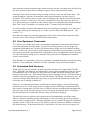
When dual serial port playback is required, the 'V' or 'Y' lead can be used to provide the two
serial port outputs from the single AntiLog connector on the end panel.
PC, PDA or other
RS232 host
PC, PDA or other
RS232 host
RS232 NULL
modem cable
RS232 NULL
modem cable
Primary serial port
'Y' Lead
AntiLog
Secondary serial port
Figure 11: Dual serial port playback
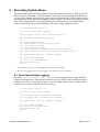
6.6 Erasing Stored Data Using the Panel Buttons
Normally, you would erase all stored data in AntiLog via the terminal menu system.
However, it is possible to erase all stored flash data using the 'On' and 'Off' buttons together
during power up if required. To do this, ensure the unit is switched off then hold down the
'Off' button. Whilst holding it down, press and hold the 'On' button until the LED lights up
green indicating the unit has started in playback mode. Now release both buttons. The same
LED turns solid yellow briefly (both red and green segments light up) to confirm the erase
operation has been actioned. If you have a terminal connected to AntiLog a message appears
informing you that the media has been erased. If you do not hold the 'On' button down for
long enough, the system will not power up and no data will be erased. This is done to prevent
accidental media erasure which could be caused by accidentally pressing both buttons
simultaneously for a short period of time with the power off.
You may not want this two button erase sequence to be available to operators in the field for
critical trials work so it is possible to disable this facility using the terminal menu system. In
this case, the only way data can be erased from the system is via the terminal menu system.
6.7 AntiLog Date and Time
AntiLog references all dates to the 1st January 2000 and time is maintained as the number of
milliseconds since midnight. If your original AntiLog system does not contain Real Time
Clock hardware then any date and time information displayed or written to the file system
defaults to relative time from switch on (amount of time elapsed assuming switch on was 1st
January 2000 00:00:00.000). Even without Real Time Clock hardware, you can enter date and
DOC/AntiLog/UG/2003001_5.1
Page 24 of 90
time manually from the terminal menu system and enter into the recording mode directly from
the menu system to allow data recordings to appear with real date and time stamps.
AntiLog is able to date and time stamp recording sessions, events and ASCII line data. The
system maintains a software clock and the battery backed hardware real time clock (if
available). The internal software clock is used to maintain time and date in normal operation.
However, if power is removed (i.e. the unit is switched off), these date and time values are
lost. When AntiLog is switched on, the software clock is set automatically from the hardware
Real Time Clock (if available) or it defaults to the 1st January 2000, 00:00:00.000.
It is now possible to transfer date and time from one AntiLog unit (running V3.1d and above)
to any other AntiLog unit running any V3 or later version of the embedded software. (See
section 7.1.1).
Date and time stamps are generally maintained with at least 1mS resolution but time stamp
accuracy can be effected by poor FLASH media performance.
6.8 User Equipment Commands
V5.1 allows you to define up to four user equipment commands which can be transmitted to
connected equipment in record mode. For a given recording channel, you can assign user
equipment commands to the 'On' and 'Off' buttons and/or assign one to the channel's polling
feature. In this way, you are able to poll equipment periodically for measurements (e.g. from a
power meter) and issue commands such as equipment reset or configuration requests using the
'On' and 'Off' buttons during record. Section 8.9 describes the User Equipment Command
system in more detail.
Note that there is a maximum of four user equipment commands shared across both recording
channels. If you change the definition of a user command, it may effect both channels.
6.9 Automated Data Recovery
When AntiLog is in record mode, all data collected is written to the single media FLASH
store. When the 'Off' button is pressed and held, AntiLog will automatically flush the current
recording buffer (up to 508 bytes) to the media store, update the media directory entry and
then power down the unit. If the internal battery slowly discharges below 4.25V then AntiLog
switches itself off as though the user pressed and held the 'Off' button. In both these cases, the
current recording buffer and the directory entry are processed and flushed to the media store
before the unit is actually switched off.
However, if no internal main battery is fitted and an external supply is used, media storage
problems can occur. If the supply power is simply switched off during record then AntiLog
does not have enough time (or power left) to flush the current recording buffer and update the
directory entry and so when the system is next powered up in playback mode, it will appear
that no data has been recorded (the directory entry will not have changed).
The AntiLog software can detect this situation and will automatically rebuild the entire
directory structure including session information as soon as the unit is powered up again in
either record or playback mode. During media data recovery, both LED segments are flashed
together (yellow). When the recovery has finished, AntiLog continues with data recording or
the playback mode. In the playback mode it is possible to view the recovery in progress on
DOC/AntiLog/UG/2003001_5.1
Page 25 of 90
the terminal screen. You may press the 'Off' button during media data recovery if you want to
abort the recovery action and make no changes to the directory structure.
Data recovery can be initiated at any time from within the General Options menu. Media data
recovery will even 'undelete' data which was erased from the Recording Options 'Erase' menu.
The media data recovery feature is unable to recover any data that was in the 508 byte
recording buffer when power was removed. This means that up to a maximum of 508 bytes
may be lost if power is suddenly removed from AntiLog instead of using the 'Off' button to
shut the unit down in recording mode.
6.10 Media Compatibility
AntiLog V5 uses a dual port file system. This new file system is backward compatible with all
previous AntiLog versions but is designed to be more interoperable when using media card
readers fitted to a PC. It supports MultiMedia Card (MMC), Secure Digital (SD) and Secure
Digital High Capacity (SDHC) media up to 32GB. It also supports MiniSD, MicroSD and
SDHC versions of these cards when fitted into an SD card adapter.
AntiLog does not use the Microsoft FAT filing system for data storage, but if you ever need to
remove the media card from an AntiLog system and fit it into a PC media card reader then the
V5 file system is more 'FAT friendly' in that it does not write to FAT sensitive areas of the
media. You still need special application software to remove the recorded data from the
media but in AntiLog V3.2 systems and earlier, the File Allocation Table used by the FAT
system could be overwritten which could cause the PC to not recognise media placed into a
media card reader slot.
6.11 Digital Bit State Logging
V5.1 has the ability to log the state of selected digital input lines on the AntiLog hardware and
insert these as events or messages in a channel's log file. This may help you monitor the status
of one or more discrete output lines from your equipment.
You can configure AntiLog to record the current digital bit state in response to a button push
or you can use a channel's polling function to record the bit state at a user defined rate.
Currently, the following digital lines are able to be monitored:Bit
number
Pin Assignment
Pin location
AntiLog
boxed
AntiLog AntiLogPro AntiLogPro
OEM
boxed
OEM
1
Secondary serial port 9-Way: Rx2, pin 8
2
Secondary serial port J3: Tx2/RTS, Pin
15
*
3
Primary serial port
9-Way: Rx1, pin 2
4
Event Input
J3: Event_In, Pin 9
*
5
Aud1,VBACK
J3: Aud1, Pin 10
**
4
Event Input
J3: EventIn, Pin 17
***
DOC/AntiLog/UG/2003001_5.1
Page 26 of 90
Bit
number
Pin Assignment
Pin location
AntiLog
boxed
AntiLog AntiLogPro AntiLogPro
OEM
boxed
OEM
5
Auxiliary Rx
J3: Pin 19
6
Auxiliary Tx
J3: Pin 20
7
D4
J3: Pin 21
8
D5
J3: Pin 22
9
DB9 Pin 1
9-Way, pin 1
*
Not applicable to AntiLog hardware revisions less than C.
** Not accessible on AntiLog hardware revision F.
*** EventIn is also routed to 9-Way connector pin 9 on AntiLogPro boxed version.
Note that bits 1 and 3 will be inverted if you use the 9 way D connector inputs for these
signals rather than CMOS levels (on the OEM version for example). The reason is because
these RS232 inputs go through an inverting function before they reach the microcontroller.
The advantage to using the RS232 inputs as digital input lines is the wide voltage range these
inputs will tolerate (-20 to +20V) which will often mean that external level conversion is not a
requirement to log the signal line state from user equipment.
A digital bit state event is inserted into a channel log file as a single ASCII event message
line. The event records each logic input level as either a logic 1 or 0. The format of the
digital bit monitor event is as follows (format depends on whether the 'Add explicit date and
time text to inserted $EVENT messages' item is enabled in the 'Record Time Stamping
Options' menu):$EVENT,DMON,n,d1,d2,d3,d4,......dn*csum
$EVENT,DMON,n,d1,d2,d3,d4,......dn,f,date,time*csum
Where:
n = Number of digital bit states recorded in this message
d1 to dn = 'n' lots of bit state readings, each either a '0' to a '1'.
f = Date and Time flag. 'V' for Valid date and time, 'R' for relative date and time.
date = Date string. Format defined in 'System Time and Date Options' menu.
time = Time string as HH:MM:SS.sss (millisecond resolution)
csum = NMEA compatible EXOR checksum
The following is an example of a digital bit state event (example from AntiLogPro
hardware):$EVENT,DMON,5,1,0,0,1,1,V,05-Mar-2010,19:22:55.190*50
DOC/AntiLog/UG/2003001_5.1
Page 27 of 90
7. General Options Menu
Type a 'G' at the main menu to enter the 'General Options' menu. This menu is important
because it is used to configure whether the entire AntiLog unit can be used in single or dual
serial port mode. It also allows access to the system date and time options as well as the menu
system settings, start up and general system features. Additionally, the general options menu
gives access to the User Option Storage menu and provides an menu item to initiate embedded
software upgrades.
==== General Options ====
(Data transfer and 'On' button aware)
<T> System time and date options
: :
*[P] Menu system on playback port settings
<U> Menu system on user defined port settings
[Q] Menu is not displayed until key press (Quiet)
: :
[D] Enable dual serial port operation
*[E] Keypad two button hold ERASE enabled
: :
<M> Media data recovery
<O> User option storage
<R> Reset current user options to factory defaults
<B> Power management and start up (Boot) options
<!> Perform embedded software upgrade
: :
<S> Start playback now (or use 'On' button)
<Esc>
?
7.1 System Time and Date Options
Select the <T> item to enter the 'System Time and Date' options menu. If your system does
not contain Real Time Clock hardware and a date and time has not already been manually
entered, the following menu appears:==== System Time and Date Options ====
(Data transfer and 'On' button aware)
(No Real Time Clock hardware detected)
!!! Current time and date not valid !!!
<T> Enter new system time and date
: :
*[0] Format: dd-mmm-yyyy HH:MM:SS.sss e.g. 20-Apr-2008 12:45:30.325
[1] Format: dd/MM/yyyy HH:MM:SS.sss e.g. 20/04/2008 12:45:30.325
[2] Format: ISO 8601 date and time
e.g. 2008-04-20T12:45:30.325
: :
<S> Start playback now (or use 'On' button)
<Esc>
?
Use the keyboard Enter (or Return) key or space bar to update this menu and hence show the
current time if a valid time and date is set.
DOC/AntiLog/UG/2003001_5.1
Page 28 of 90
Use this menu to select how you would like the date formatted in AntiLog. Select either text
format ([0]) or numeric format ([1]).
Use the <T> item in this menu to enter a date and time manually. You must enter a time and a
date to have the entry accepted. Anticyclone Systems Ltd recommend you always use UTC
time and date for data recording to ensure you don't get confused with time zones during data
analysis.
==== New Date and Time Entry ====
Date formats: dd-mmm-yyyy, dd/mmm/yyyy, dd-MM-yyyy or dd/MM/yyyy
Time formats: HH:MM:SS.sss, HH:MM:SS or HH:MM
Example: 04-Apr-2008 23:30:45 (Use 'Control-P' to edit the current date and time)
New Date and Time:
The date and time are only set when you hit the Enter or Return key at the terminal, so it is
possible to type in a date and time slightly ahead of real time and hit Enter at the moment the
time and date become valid. This will set the date and time as accurately as possible from
keyboard input. You can edit the current time and date value by typing Control-'P'.
If a real time clock is present, the entered time and date will be written to it during this
process, else the time and date will be valid while the unit remains in playback mode with the
power on. You can use the 'Record Data Now' option in the Recording menu to use this date
and time without powering down your unit so that recording time stamps contain valid time
and dates.
Internally, all time and dates are related to 1st January 2000 at midnight. If no real time clock
is available, this time will be set at power up and all timing will be relative to this time and
date. See the description of AntiLog date and time in section 6.7 for more details.
7.1.1 Date and time transfers to other units
If you need to use a number of AntiLog units in a trial, it is a good idea to ensure the date and
time held on each is as accurate as possible. To transfer date and time effectively from one
unit to another (and to save time setting up your units) use the date and time transfer function
in the 'System Time and Date Option' menu.
Ensure all units ready to receive time and date are switched on in playback mode with the
same menu serial port settings as this transmitting unit and also ensure the settings locks are
off on all receiving units.
==== System Time and Date Options ====
(Data transfer and 'On' button aware)
(Real Time Clock hardware detected)
04-Apr-2008 14:38:20.753
<T>
: :
<X>
: :
*[0]
[1]
[2]
Enter new system time and date
Perform time transfer to another AntiLog unit
Format: dd-mmm-yyyy HH:MM:SS.sss e.g. 20-Apr-2008 12:45:30.325
Format: dd/MM/yyyy HH:MM:SS.sss e.g. 20/04/2008 12:45:30.325
Format: ISO 8601 date and time
e.g. 2008-04-20T12:45:30.325
DOC/AntiLog/UG/2003001_5.1
Page 29 of 90
: :
<S> Start playback now (or use 'On' button)
<Esc>
?
Select the <X> item to enter the time transfer mode on the transmitting unit.
==== Time Transfer to another AntiLog Unit ====
Replace this terminal connection now with a NULL modem connection
to each AntiLog unit in turn to transfer date and time.
Press the 'On' button on this unit to perform each date and time transfer.
<Esc>
?
Connect a NULL modem cable from this unit to the first AntiLog unit to receive date and time
and press the 'On' button on the transmitting unit. Wait about two seconds and then you can
disconnect and reconnect additional units as you want, pushing the 'On' button to perform the
date and time transfer to each.
The units that receive date and time in this way should be synchronised to within about a
millisecond of each other when the transfer occurs. Note that the receiving AntiLog units do
not need to be running V5.1 to accept the date and time. All V3.0 and above versions will
accept time transfers. However, you need V3.1d (or above) to support transmitting date and
time.
7.1.2 1PPS time synchronisation output
For some trials work, an accurate time reference is an important part of the data collection
process. One of the advantages to logging data on a dual channel data recorder is that the two
data sources share a commonly synchronised time source for time stamped data. The OEM
version of the AntiLogPro hardware extends this concept one stage further and offers a means
to synchronise many other pieces of equipment that accept a 1 pulse per second (1PPS) input,
including other AntiLog data units.
Although no time value itself is transmitted over the 1PPS interface, you can use the fact that
it is always on a 1 second boundary to post process corrections for other equipment whose
time is perhaps slowly drifting with respect to the reference AntiLog unit which is
transmitting the 1PPS source. For example, you could connect one or more AntiLog units to
the first via their 'EventIn' lines and log those EventIn events which will give you time
stamping to 1mS resolution when you post process all of your data.
The AntiLogPro hardware transmits a 1PPS square wave output on the dedicated '1PPSout'
header pin (pin 23 on on J3) with a 50% duty cycle. The positive edge represents the onboard 1 second epoch time reference (start of every 1 second count).
7.2 Menu System Port Settings
By default, the terminal menu system is displayed on the serial port assigned for data playback
([P] selected in the 'General Options' menu). In this case, changes to the playback port
settings (channel 1) will automatically apply to the menu system.
DOC/AntiLog/UG/2003001_5.1
Page 30 of 90
Use the <U> menu item in the 'General Options' menu to define the terminal menu system's
own serial port settings which are then independent of any other settings. If the Dual Serial
Port option is enabled, you can assign the menu system to one port and the data playback to
another. This would then prevent any menu display text being transmitted to equipment
connected to the playback port.
If you request the 'Reset all options to factory defaults' item from the main 'General Options'
menu, the menu port settings are reset to defaults and the menu system is linked back to the
playback port.
7.3 Menu Quiet
If the Menu Quiet ([Q]) item is selected, AntiLog will not display the opening system menu
until the user has entered a key (such as the space bar or return keys). This can be useful if
you want AntiLog to transmit recorded data to equipment exactly as it was recorded without
the main AntiLog system menu being transmitted to the equipment first if the terminal menu
is assigned to the playback serial port. Press and hold the 'On' button to put AntiLog in
playback mode and then push the 'On' button again to start transmitting data. The AntiLog
menu won't appear at the end of the transfer until a key has been pressed even if the menu
quiet option is not selected.
Please note that with Menu Quiet selected, other users who may have used older versions of
the AntiLog embedded software may think your AntiLog unit is not functioning because a
menu does not appear in playback mode. You can always use the keyboard Space bar or the
Return key to refresh any AntiLog terminal menu.
7.4 Enabling the Dual Serial Port Mode
Select the [D] item in the 'General Options' menu to enable/disable the dual serial port
feature. When disabled, the primary AntiLog serial port supports RTS/CTS hardware
handshaking. When dual serial port mode is enabled, the RTS/CTS lines on this port become
the secondary serial port transmit and receive lines and a custom Dual Serial Port cable is
required ('V' or 'Y' lead). If the Dual Serial Port feature is not enabled in this menu then dual
serial port options in the recording, playback and menu user defined port settings menus will
not be available.
If you do not need to use the dual serial port feature for record or playback, don't enable it.
This will simplify the menu system and the RTS/CTS lines will default to the correct line state
(even if RTS/CTS playback handshaking for the serial port is not actually selected). In dual
serial port mode, the RTS/CTS lines are the second serial port and when these are idle, they
are not in the correct state for RTS/CTS handshaking. For this reason, you should always use
a custom Dual Serial Port cable for dual serial port mode or ensure that equipment connected
to AntiLog (e.g. a PC) is not configured for hardware handshaking.
7.5 Two Button Erase
If you are working on important trials you may want to minimise the chances of losing
important recorded data. As such, you can disable the ability of a user in the field to erase the
contents of the flash media by holding down the 'Off' and the 'On' buttons at start-up (See
section 6.6). If a star character (*) does not appear to the left of the menu item then the only
way to erase stored data is via the 'Recording Options' menu using a serial port terminal.
DOC/AntiLog/UG/2003001_5.1
Page 31 of 90
[E] Keypad two button hold ERASE enabled
7.6 Media Data Recovery
Select the <M> option in the 'General Options' menu to force the Media Data Recovery feature
to start. You will be asked for confirmation and then the recovery will take place. On screen
you will see progress made so far, both red and green LEDs will flash together and the 'Off'
button can be used at this time to terminate the action without making any changes to the
media store.
When data recovery has finished, AntiLog returns to and displays the main menu. You can
then see exactly how much data and how many sessions have been recovered.
Note that the media data recovery feature can even 'undelete' data which was erased with the
Erase All item in the 'Recording Options' menu as long as no new data has been written to
AntiLog in record mode since the erase command was issued.
7.7 User Option Storage
You can save and load complete sets of user options to prevent having to reconfigure a unit
using all the menu items each time. Up to four option sets can be saved into non volatile
storage which means the saved option sets will not be lost when all sources of power are
removed. This feature is useful if you are involved with different projects where the settings
are different for each project but you need to share an AntiLog unit between the projects.
==== User Option Storage ====
*[1]
[2]
[3]
[4]
?
Store
Store
Store
Store
1:
2:
3:
4:
<empty>
<empty>
<empty>
<empty>
<L> Load into current user options from selected store
<S> Save current user options to selected store
<E> Erase selected store
<Esc>
7.7.1 Saving a set of user options
To save the current active options to a named options store, first select a store by typing '1' to
'4'. The currently selected store is the one marked with a '*' character. Select the <S> item to
request a save. You will be prompted to enter a descriptive name for the new option set. The
store name can be up to a maximum of 32 characters and doesn't have to be unique.
Enter a new store name for these options.
- You must use the 'On' button to confirm, 'Off' button or <Esc> key
to abort.
- Use Control-P to edit the existing store name.
New store name: Ch1=My Inertial Nav, Ch2=My GPS
While entering the store name, you can pull back the existing name for this store for editing (if
present) using the Control-'P' keyboard combination. The store name can contain spaces and
printable characters such as +, _, &, etc. If you do not enter a store name but proceed with the
save operation then the name will appear in the list as <no name>.
DOC/AntiLog/UG/2003001_5.1
Page 32 of 90
Press the 'On' button to confirm the save operation or the 'Off' button or terminal Escape key
to abort the operation. Pressing the 'On' button will start the saving process and you may have
to wait a few seconds for the process to complete.
[Saving current options, please wait...Save complete]
Pressing the keyboard Enter or Return keys during store name entry will not start the save, you
must use the 'On' button to prevent accidental overwriting of stored options from random
character input to the menu system. If the store chosen already had options saved to it, these
will now be overwritten with the currently active options. The following example shows a set
of user options written to store 2:==== User Option Storage ====
[1]
*[2]
[3]
[4]
?
Store
Store
Store
Store
1:
2:
3:
4:
<empty>
Ch1=My Inertial Nav, Ch2=My GPS
<empty>
<empty>
<L> Load into current user options from selected store
<S> Save current user options to selected store
<E> Erase selected store
<R> Reset current user options to factory defaults
<Esc>
7.7.2 Loading a set of user options
Ensure the store number is selected for the set of options you wish to retrieve by entering a
number '1' to '4'. The active store is the one with the '*' symbol next to it. Select the <L> item
to load the saved set of options into the currently active options.
Load options from named store: Inertial navigation+GPS trials
You must use the 'On' button to confirm, 'Off' button or <Esc> key to abort
You must confirm the operation using the 'On' button, not the keyboard Enter or Return key.
If you push the 'On' button, the loading operation will start and a confirmation will be printed
to the terminal screen. The saved settings are now the active settings and you may now need
to change your terminal port settings and baud rate to match any changes to the menu port and
baud settings (you will be prompted for this if such action is required).
Once a set of options have been loaded, they can be altered as usual using the menu system.
For example, it may be quicker to load in a set of known options and modify them rather than
modify factory default settings for a given trial.
7.7.3 Erasing a set of user options.
For completeness, if you would like to erase a store's content you can select the store first and
then use the <E> item. You must confirm the erase operation using the 'On' button, not the
keyboard Enter or Return key. When the erase has completed, the store location will show
<empty> for the selected store name. Note that you do not need to erase a selected store
before writing new content to that store location, just use the save item as a save will always
overwrite any existing store content.
DOC/AntiLog/UG/2003001_5.1
Page 33 of 90
7.8 Power Management and Start Up Options
Select the <B> option from the 'General Options' menu to enter the 'Power Management and
Start Up Options' menu. Here you can enable or disable automatic power saving and
configure how your AntiLog unit starts up.
==== Power Management and Start Up Options ====
(Data transfer and 'On' button aware)
*[A] Automatic power saving enabled
[F] Always start up in playback mode (Forced Playback)
<Esc>
?
7.8.1 Automatic power saving
Selecting the [A] item in the Power Management and Start Up Options menu enables
automatic power saving. In common with other electronic computing devices, it is possible to
reduce the overall power consumption if you are able to reduce the effective system clock
frequency. AntiLog is able to dynamically change this value to give power consumption
savings during operation. When the power saving mode is disabled, AntiLog runs at full
clock speed regardless of selected baud rates and whether the unit is in recording or playback
mode. Enabling automatic power saving mode allows proportional changes to the system
clock frequency based on the selected settings which can for example reduce power
consumption by 40% or more when operating with baud rates equal to or less than 38400.
Power saving mode is enabled by default and only has an effect if the combined channel baud
rates are less than 115200 for a given operating mode (e.g. playback). AntiLog automatically
chooses the optimum microcontroller clock frequency for the current mode of operation. If
you are operating AntiLog in recording mode, the recording baud rates and settings are used
for this calculation, else the playback and/or menu baud rates are used.
There are no significant disadvantages to using the automatic power save mode for recording
data. For playback, there can be a slight reduction in the data transfer rates (<10%) which is
only true if a playback baud rate less than 115200 is selected. For this reason, you are able to
disable the automatic power saving mode for ultimate playback and recording performance.
7.8.2 Forced playback
If you want to always start your unit in playback mode then select the Forced Playback feature
in the 'Power Management and Start Up Options' menu. When this item is selected, AntiLog
will always start up in playback mode (e.g. regardless of the length of time the 'On' button is
pushed at start up). You can then select recording mode from the playback menu system (see
the 'Recording Options' menu, section 8) rather than rely on a short button press during
startup. This option is also useful if you want to gain control over a remote OEM ('P'
hardware option) unit every time power is applied.
==== Power Management and Start Up Options ====
(Data transfer and 'On' button aware)
*[A] Automatic power saving enabled
*[F] Always start up in playback mode (Forced Playback)
<Esc>
?
DOC/AntiLog/UG/2003001_5.1
Page 34 of 90
When active, the main menu will show that forced playback is selected:AntiLog_OEM-MR V5.1, Serial number ASL/16/001, 03-Oct-2009 11:02:21.203
(135922 bytes recorded in 2 sessions, 0% of 485.2MB)
(FORCED PLAYBACK mode. Data transfer and 'On' button aware)
7.8.3 Forced playback via 'EventIn' line
For AntiLog OEM customers that have the 'P' hardware option installed, there is a feature
added to allow units to automatically power up in playback mode rather than the default
record mode based on the state of the 'EventIn' pin on the J3 OEM header. If the 'EventIN' pin
is held low when power is applied (and this feature is enabled in the menu system) then the
unit will always start up in the playback mode.
An extra menu item appears in the new Power Management and Start Up Options menu to
allow you to define this start up behaviour. An example follows which shows 'EventIn' forced
playback enabled.
==== Power Management and Start Up Options ====
(Data transfer and 'On' button aware)
*[A] Automatic power saving enabled
*[P] Setting OEM line 'EventIn' low forces playback mode at start up
[F] Always start up in playback mode (Forced Playback)
<Esc>
?
Note that the [P] item shown in the example will not be selectable if 'Forced Playback' is
instead enabled.
7.9 AntiLog Software Upgrades
The embedded AntiLog software can be upgraded via the serial port. Instructions on how to
do this are supplied with a specific upgrade. If you decide to select this item you will be asked
if you really want to do this and if you confirm this action, the system bootloader will be
activated.
If you accidentally activate the bootloader, simply switch the unit off as normal by holding the
'Off' button down for at least one second. When you next switch the unit on, it will run the
existing software again as normal.
Note that if your system is a custom solution which is not supplied with the bootloader option,
the '!' menu option will not be present and you cannot upgrade the embedded software via the
serial port.
7.10 Restoring Factory Defaults
You can reset the unit to factory defaults to ensure you know the exact state of AntiLog before
making changes to the settings yourself. You will be prompted to confirm this operation
before it takes place. There is no 'undo' facility!
Setting the factory defaults does not erase any existing recorded data on the media and it also
does not change any settings saved into the named User Option Management stores. The
factory defaults are as follows:
DOC/AntiLog/UG/2003001_5.1
Page 35 of 90
Option
Default State
Dual Serial Port Mode
Off
Record baud rate
4800
Record RS232 data bits
8
Playback baud rate
115200
Playback RS232 data bits
8
Playback parity
None
Playback stop bits
1
Menu system locked to playback port
Yes
Menu Quiet
Off
Menu system baud rate
115200
Menu system RS232 data bits
8
Menu system parity
None
Menu system stop bits
1
Record data filter
Record All
Time stamp line data
Off
Date and time added to $EVENT messages
Yes
End Of Line Character Selection
Auto
Record 'On' and 'Off' button events
Disabled
Record 'On' button sends user command
No
Record LEDs enabled
Yes
Playback LEDs enabled
Yes
Playback mode
RAW
Playback insert session headers
Off
Playback insert time stamps
Off
Playback RTS/CTS handshaking
Disabled
Two button erase
Enabled
Automatic Power saving mode
Enabled
Forced Playback
Off
Asserting 'EventIn' forces playback mode
Off
Escape key can abort playbacks
Off
Lock User Options
Off
Note that if your hardware supports Dual Serial Port operation, the Dual Serial Port Mode in
the 'General Options' menu will be disabled by default. However, it is possible to force this to
enabled by default as a factory set option for those who will always using the system in the
dual serial port configuration.
DOC/AntiLog/UG/2003001_5.1
Page 36 of 90
8. Recording Options Menu
The 'Recording Options' menu available from the main menu controls how AntiLog records
RS232 data in record mode. The actual menu content may vary depending on the hardware
you are using, whether dual serial port mode has been enabled in the 'General Options' menu
and whether the 'Dual channel data logging' item is selected. The following example shows a
typical 'Recording Options' menu using AntiLogPro with dual serial port enabled in the
'General Options' menu, but not selected here for record (single channel record):==== Recording Options ====
[D] Dual channel data logging
: :
<P> Configure serial port {M:115200,8,N,1,-}
: :
<M> Recording method {Record All}
: :
<T> Time stamping {none}
<X> Define ASCII end of line character
<1> 'On' button actions
<2> 'Off' button actions
<U> User equipment commands and polling functions
<I> Event logging options for 'EventIn' digital input
: :
<W> Media write options {Normal logging}
: :
*[L] Panel LEDs enabled
<E> Erase all recorded data
<R> Record data now
<Esc>
?
1. The “Media write options” item only appears on AntiLogPro hardware
2. The “Event logging options” item only appears for OEM versions of the hardware
8.1 Dual Channel Data Logging
Select the '[D] Dual channel data logging' item to toggle between single and dual
channel recording mode. Note that this item will not be available if dual serial port mode is
switched off in the 'General Options' menu. The 'Recording Options' menu changes to the
example below if dual serial port record is selected:==== Recording Options ====
*[D] Dual channel data logging
: :
<1> Configure data recording for Channel 1
<2> Configure data recording for Channel 2
: :
<W> Media write options {Normal logging}
: :
*[L] Panel LEDs enabled
<E> Erase all recorded data
<R> Record data now
<Esc>
?
DOC/AntiLog/UG/2003001_5.1
Page 37 of 90
Enter a '1' to edit channel 1's options, enter a '2' to edit channel 2 options. The Media writing
options and the other items in this menu are not channel specific.
8.2 Configuring a Serial Port for Record
Use the configure serial port (<P>) option in the 'Recording Options' menu to set the serial
port baud rate and number of RS232 data bits per character to use when recording data. If
Dual Serial Port operation is selected in the 'General Options' menu, this option also allows
you to specify which port is connected to the data source and you will see options [1] and
[2] as displayed in the following example, otherwise these options will not be present.
==== Record Serial Port Settings {M:4800,8,N,1,-} ====
*[1] Record from main serial port
[2] Record from secondary serial port
[3] Record from auxiliary serial port
: :
<B> Set serial port baud rate
[5] 5 data bits
[6] 6 data bits
[7] 7 data bits
*[8] 8 data bits
: :
*[N] No parity
[E] Even parity
[O] Odd parity
[T] Two stop bits
: :
<I> RS232 signal line inversion
<Esc>
?
1. The “RS232 signal line inversion” item only appears on AntiLogPro hardware
2. The “Record from auxiliary serial port” item only appears on AntiLogPro OEM hardware
Select <B> to enter the baud rate select sub menu (see section 11). You can also use this
menu to configure the number of data bits, parity and stop bit settings for data recording.
8.2.1 RS232 signal line inversion
AntiLogPro users have an additional sub menu item in the 'Record Serial Port Settings' menu
which allows individual RS232 line inversion to be specified.
==== RS232 Signal Line Inversion Options ====
*[N] Normal
[R] Invert
[T] Invert
[B] Invert
<Esc>
?
RS232 signal line operation
Rx receive signal line logic (!R, will read CMOS/TTL RS232)
Tx transmit signal line logic (!T)
both Rx and Tx signal line logic (!B)
In this way, it is possible to log some CMOS RS232 data sources, such as those transmitted
directly from OEM GPS receivers without the need to convert the signals to true RS232 levels
first. RS232 line driver level conversion normally involves a logical signal inversion process
DOC/AntiLog/UG/2003001_5.1
Page 38 of 90
and so AntiLogPro is now fully configurable to cope with all combinations of possible data
inversion.
Please note that although it is possible to invert the transmit line which would then mean the
logic sense is correct for CMOS RS232 transmissions, the drive level output from AntiLogPro
is always at RS232 line levels which means you will see negative voltage as well as positive
values output from the AntiLogPro transmit pin.
8.3 Recording Method
The 'Recording Method' sub menu allow you to define how AntiLog captures your incoming
data. For dual channel capture, these settings can be (and often are) different for each
channel. Per channel, you can choose to record all data, record filtered GPS NMEA sentence
data or perform ASCII line sub sampling to reduce the amount of collected data.
You can also select the 'do not log' item which prevents incoming serial port data from being
logged but does allow Event inputs and digital bit state polling and other forms of internal
capture to be logging on that channel. As another example, you may want to use the second
channel to output user equipment commands but are not interested in the data it returns and
hence you may save on media storage requirements for a given trial.
==== Recording Method for Channel 1 ====
*[A] Record all data
<N> Record filtered GPS NMEA
<M> Record ICD-GPS-15x
<S> ASCII line sub sample filter
[X] Do not log incoming data for this channel
: :
[G] Go to the other channel
[+] Copy these options to the other channel
<Esc>
?
8.3.1 Recording all data
You may wish to record everything that appears at the RS232 port during record mode or have
AntiLog automatically filter the data it stores to the flash media. Select the [A] item in the
Recording Options menu to record everything without any filtering.
If you are recording ASCII line data (e.g. GPS NMEA data), you can optionally select the <T>
item and choose time and date tagging options for the start of each data line. The line time
and date can then be optionally embedded into the playback data stream and can also be used
directly to assist real time data playback.
8.3.2 Filtering GPS NMEA messages
If you are logging GPS NMEA sentences, you can choose to record everything using the
'Record all data' item in the 'Recording Options' menu or you can select which NMEA
sentences will be logged from a fixed list of GPS NMEA sentence names. Logging only
selected NMEA sentences helps to reduce total trial storage requirements and improves data
upload times. Recording only selected sentences may even simplify subsequent data
processing.
To select which GPS NMEA sentences to record, select the <N> item in the Recording
Options menu and then select which sentences to record. A star ('*') to the left of the
DOC/AntiLog/UG/2003001_5.1
Page 39 of 90
keyboard option indicates that this sentence will be recorded and it is toggled each time the
menu item is selected. Incoming sentences which are not selected in this list will not be
logged during a recording session. The following example shows that only GPS NMEA
sentences starting with GPGGA and GPRMC will be logged.
==== NMEA Sentence Filter ====
*[0] GPGGA [1] GPGSA [2] GPGSV *[3] GPRMC [4] GPBOD [5] GPGLL [6] GPRTE [7] GPVTG [8] GPZDA [9] GPRMB [E] PQNQR [F] PQNQI [G] PQNQP [H] PQNQV [I] PQNQT [J] PRWIZCH
<Esc>
?
GPS Solution
DOP and Active Satellites
Satellites in View
Recommended Minimum GPS
Bearing, Origin to Destination
Geographic Position, Latitude, Longitude
Routes
Track and Ground Speed
UTC Date and Time
Recommended Minimum Navigation Information
QinetiQ HSGPS Command Response
QinetiQ HSGPS Miscellaneous Information
QinetiQ HSGPS Extended Position
QinetiQ HSGPS Extended Satellites in View
QinetiQ HSGPS Time and date
- NAVMAN Jupiter specific
If you select all of the sentence names in the list (all items appear with a '*') then only these
sentences selected will be recorded, ALL OTHERS WITH OTHER NAMES ARE NOT
LOGGED. If you need to record all incoming data, return to the 'Recording Options' menu
and select <A>. If you want to filter NMEA sentences again, select the <N> item from the
'Recording Options' menu once more and the sentences you previously selected will still be
remembered.
8.3.3 Sub Sampling ASCII Line Data
If your source data is formatted as ASCII text lines (e.g. NMEA, equipment sensor data, etc.)
it is possible to write a sub sampled selection of this data to the flash store to help reduce the
overall storage requirements and to reduce data upload times. AntiLog supports a simple, but
powerful method of selecting sub sampled data. Selecting [S] from the 'Recording Options'
menu brings up the following sub menu.
==== ASCII Line Sub Sample Filter Options ====
?
<S> First line of frame starts with:
<N> Record 1 in every: {2} frames
<Esc>
When AntiLog is in record mode with the sub sample filter selected, it looks for an ASCII text
line starting with the characters specified (case sensitive). No data is recorded during this
process. The line detected and any following data lines are then recorded until this line is
found again in the source data. At this point, data recorded is disabled until the line is found
again. If this is the 'Nth' time this data line has been detected, data recording will be enabled
again, and so on. in this way, sub sampled frames of text line data are recorded.
DOC/AntiLog/UG/2003001_5.1
Page 40 of 90
Select the <S> item in the 'ASCII Line Sub Sample Filter Options' menu allow data entry of
the first few characters of the first line you want sub sampled in the data (in the example
above, $GPGGA has been entered). As you enter new characters, they will be echoed to the
terminal. Type the RETURN key to accept these changes or the Escape key to cancel data
entry and restore the previous value. If you want to delete the last character typed, use the
keyboard BACKSPACE key (or on some keyboards, the DEL key) and the current entry will
be re-written to the terminal on the next line. The first line string pattern is limited to a
maximum of 25 characters. If an empty string is entered, the sub sampling system will match
all text lines regardless of content.
Select the <N> item in the 'ASCII Line Sub Sample Filter Options' menu to enter the frame
selection rate. The menu system prompts for a new value below the sub menu. Enter a
number in the range 2 to 99999999. Use a backspace (or on some keyboards, the DEL key) to
delete the last digit typed. The frame periods are automatically restricted to the range 2 to
99999999 when the RETURN key is used to confirm a new entry. Use the Escape key to
cancel data entry and restore the previous value. The previous value is also restored if
RETURN is typed with no digits entered.
The following example demonstrates the sub sampling of a NMEA data source for the
following Sub Sample filter options:==== ASCII Line Sub Sample Filter Options ====
?
<S> First line of frame starts with: $
<N> Record 1 in every: 3 frames
<Esc>
Event
Recording Started->
Second logged Frame->
Third logged Frame->
Forth logged Frame->
Fifth logged Frame->
Sixth logged Frame->
Seventh logged Frame->
Eighth logged Frame->
Ninth logged Frame->
Source Data
$GPGSV,3,3,11,16,.....
$GPRMC,173840,A,5.....
$PRWIZCH,13,7,10,.....
$GPGGA,173841,511.....
$GPGSA,A,3,13,10,.....
$GPRMC,173841,A,5.....
$PRWIZCH,13,7,10,.....
$GPGGA,173842,511.....
$GPGSA,A,3,13,10,.....
$GPGSV,3,1,11,13,.....
$GPGSV,3,2,11,01,.....
$GPGSV,3,3,11,16,.....
$GPRMC,173842,A,5.....
$PRWIZCH,13,7,10,.....
$GPGGA,173843,511.....
$GPGSA,A,3,13,10,.....
$GPRMC,173843,A,5.....
$PRWIZCH,13,7,10,.....
$GPGGA,173844,511.....
$GPGSA,A,3,13,10,.....
$GPGSV,3,1,11,13,.....
$GPGSV,3,2,11,01,.....
$GPGSV,3,3,11,16,.....
$GPRMC,173844,A,5.....
$PRWIZCH,13,7,10,.....
$GPGGA,173845,511.....
$GPGSA,A,3,13,10,.....
.....
Sub Sample Logic: N = 3, Start=$
<- First line Match '$', start logging
<- Line match 1, stop logging
<- Line match 2, stop logging
<- Line match 3, start logging
<- Line match 1, stop logging
<- Line match 2, stop logging
<- Line match 3, start logging
<- Line match 1, stop logging
<- Line match 2, stop logging
<- Line match 3, start logging
<- Line match 1, stop logging
<- Line match 2, stop logging
<- Line match 3, start logging
<- Line match 1, stop logging
<- Line match 2, stop logging
<- Line match 3, start logging
<- Line match 1, stop logging
<- Line match 2, stop logging
<- Line match 1, stop logging
<- Line match 2, stop logging
<- Line match 3, start logging
<- Line match 1, stop logging
<- Line match 2, stop logging
<- Line match 3, start logging
<- Line match 1, stop logging
<- Line match 2, stop logging
<- Line match 3, start logging
The next example demonstrates the sub sampling of the same NMEA data source but using a
specific start line string shown in the following Sub Sample filter options:==== ASCII Line Sub Sample Filter Options ====
DOC/AntiLog/UG/2003001_5.1
Page 41 of 90
?
<S> First line of frame starts with: $GPGGA
<N> Record 1 in every: 3 frames
<Esc>
Event
Recording Started->
First logged Frame->
Second logged Frame->
Source Data
$GPGSV,3,3,11,16,.....
$GPRMC,173840,A,5.....
$PRWIZCH,13,7,10,.....
$GPGGA,173841,511.....
$GPGSA,A,3,13,10,.....
$GPRMC,173841,A,5.....
$PRWIZCH,13,7,10,.....
$GPGGA,173842,511.....
$GPGSA,A,3,13,10,.....
$GPGSV,3,1,11,13,.....
$GPGSV,3,2,11,01,.....
$GPGSV,3,3,11,16,.....
$GPRMC,173842,A,5.....
$PRWIZCH,13,7,10,.....
$GPGGA,173843,511.....
$GPGSA,A,3,13,10,.....
$GPRMC,173843,A,5.....
$PRWIZCH,13,7,10,.....
$GPGGA,173844,511.....
$GPGSA,A,3,13,10,.....
$GPGSV,3,1,11,13,.....
$GPGSV,3,2,11,01,.....
$GPGSV,3,3,11,16,.....
$GPRMC,173844,A,5.....
$PRWIZCH,13,7,10,.....
$GPGGA,173845,511.....
$GPGSA,A,3,13,10,.....
.....
Sub Sample Logic: N = 3, Start=$GPGGA
<- Line ignored
<- Line ignored
<- Line ignored
<- First line Match, start logging
<- Line match 1, stop logging
<- Line match 2, stop logging
<- Line match 3, start logging
<- Line match 1, stop logging
8.3.4 No log method
There are times when you need to capture events, digital bit state, button pushes, and the like
and write them into a log file for a channel but you are not interested in any RS232 data
presented at that channel's RS232 input. For example, if you were to use the secondary serial
port connection to log the digital bit state of an external signal line, each time it transitioned,
you may also get a random looking RS232 character presented at the input channel which
would be of no value.
Characters such as this at the input would also prevent the ASCII line insertion mechanism
from working as the system waits for a clean 'end of ASCII line' sequence before it can insert
more events into a channel's log file. Logging a few random characters will block this event
insertion mechanism and will therefore completely block further digital event storage.
Note that selecting this recording method does not prevent the sending of user commands
either from button pushes or from the polling mechanism. It is therefore safe to use this
option if you are only using a channel to define user commands and are not interested in any
data presented to that channel's RS232 input.
8.4 Time Stamping Recorded Data
AntiLog can automatically time stamp incoming data and embed this information in the
recorded data for each recording channel. You are then able to optionally expand this date
and time information later when you play back the data. AntiLog uses its own clock reference
for the time stamping (See section 6.7).
AntiLog uses efficient data compression to ensure embedded date and time stamps do not
require excessive storage. For example, although the date and time stamp when played back
DOC/AntiLog/UG/2003001_5.1
Page 42 of 90
in ASCII is up to 25 bytes long (depending on the chosen output format), the actual overhead
in storing date and time for ASCII line time stamping is only an extra six bytes giving a full
date and time resolution to 1mS.
As an example, if you have the 'Record all data' item selected in the 'Recording Options'
menu, then entering a <T> at this menu will bring up the 'Time Stamping options for Record'
menu as follows:==== Record Time Stamping Options ====
*[D] Disable time stamping
[A] ASCII line time stamping (ASCII line data, e.g. GPS NMEA)
[8] ASCII 8 bit line time stamping (line data is 8 bit)
<N> Insert time stamp before every {1} binary byte
: :
*[E] Add explicit date and time text to inserted $EVENT messages
<Esc>
?
Use the [D] item to disable time stamping for this channel. Not all of the options in the Time
Stamping menu will always be available depending on the recording mode. For example, if
the 'Record filtered GPS NMEA' item is selected in the 'Recording Options' menu, the 'N' byte
time stamping item will not be present.
8.4.1 ASCII line time stamping
Use the [A] item to select ASCII line time stamping. A time stamp will be inserted at the
start of each ASCII line. This is ideal for GPS NMEA sentences and power meter readings for
example. In this mode, the top bit in each eight bit character received is cleared before being
written to the FLASH store and so this mode is not suited to binary data recording but does
consume the least amount of data storage on the FLASH media.
8.4.2 ASCII 8 bit line time stamping
Use the [8] option to time stamp ASCII line data where full eight bit recording is required
(e.g. line data may have characters above decimal value 127).
8.4.3 'N' byte binary time stamping
If you are recording pure binary data (Record All), you may wish to select 'N' byte time
stamping. Without knowing the format of the data itself, it would not normally be possible to
time stamp binary data. However, in this mode, a time stamp is recorded ahead of every 'N'
bytes of incoming data. The time stamp refers to the time the first byte in a block of 'N' bytes
was received. The time stamp information can be expanded in the playback data or not output
at all. The time stamp can also be used to assist with real time playback. Using this time
stamping method allows full binary data capture but with the addition of embedded timing
information.
It is possible to set N to 1, so a time stamp exists for every byte recorded in a session. This
increases the FLASH media file size by a factor of 7 but this feature can be extremely valuable
for debugging system output. Selecting <N> in the 'Time Stamping Options for Record' menu
prompts for a value for 'N' which must be in the range 1 to 65535:-
DOC/AntiLog/UG/2003001_5.1
Page 43 of 90
Enter number of bytes to follow each time stamp (1 to 65535): 5
Enter a number followed by the Enter or Return key on your terminal keyboard.
==== Record Time Stamping Options ====
[D] Disable time stamping
[A] ASCII line time stamping (ASCII line data, e.g. GPS NMEA)
[B] Binary line time stamping (line data is 8 bit)
*<N> Insert time stamp before every {5} binary bytes
: :
*[E] Add explicit date and time text to inserted $EVENT messages
<Esc>
?
When you play back data recorded in a session with 'N' byte time stamping, the session header
contains the 'N' value to help with data post processing.
8.4.4 Specifying date and time for $EVENT message
When you request event logging (for example, button events, see section 8.6), the $EVENT
messages written to a channel log file by default contain a date and time field. The date and
time are stored in ASCII rather than a compressed binary format. You therefore have the
option to turn off date and time output in $EVENT messages to reduce storage requirements if
you are recording high volumes of events.
If you record with time stamping enabled, the $EVENT messages will be time stamped anyway,
so you may not need date and time added to the ASCII $EVENT messages. A '*' character to
the left of the [E] item in the Time Stamping Options for Record menu means date and time
will be added to ASCII $EVENT message written to the channel log file.
8.5 Defining the End Of Line Character
When reading in lines of ASCII data, AntiLog needs to know when a complete ASCII line has
been read in. ASCII text lines generally end in carriage return (<CR>) followed by line feed
(<LF>), carriage return only or line feed only.
==== ASCII End Of Line Character Selection ====
[R] ASCII Return (<CR>, 13 dec, 015 oct, 0x0d hex)
[L] ASCII Line Feed (<CR><LF> or <LF>, 10 dec, 012 oct, 0x0a hex)
<U> User defined
: :
*[A] Auto detect (<CR>, <LF> or <CR><LF>)
<Esc>
?
If you leave Auto Detect selected ([A]), AntiLog will attempt to determine the end of line
sequence itself based on the assumption that lines will end in either <CR>, <LF> or
<CR><LF>. If you know what the line termination character is, select it here and AntiLog
will not have to perform a search for possible end of line combinations. The advantage in
telling AntiLog in advance what the end of a line will be is that the auto detect mechanism can
never be 100% reliable in every situation (because of possible data corruption for example).
However, for most users, the auto detect end of line feature will perform well in nearly all
situations.
DOC/AntiLog/UG/2003001_5.1
Page 44 of 90
V5.1 allows you to define the end of line character. This can be any single character in the
value range 0 to 255 so it is possible in some circumstances to use this feature for time
stamping binary data. In the example that follows, a character value of 35 (the '#' character)
has been entered to represent the character used at the end of incoming data lines from a
custom data source. Select the <U> item to enter a line character value:Enter end of line character value (in decimal): 35
==== ASCII End Of Line Character Selection ====
[R] ASCII Return (<CR>, 13 dec, 015 oct, 0x0d hex)
[L] ASCII Line Feed (<CR><LF> or <LF>, 10 dec, 012 oct, 0x0a hex)
*<U> User defined (35 dec, 0x23 hex)
: :
[A] Auto detect (<CR>, <LF> or <CR><LF>)
<Esc>
?
8.6 Defining the 'On' and 'Off' button functions for record
The <1> and <2> items in the 'Recording Options' menu define the responses to the 'On' and
'Off' buttons during record. If there is a '*' character to the left of these items, this indicates
that a button has been configured to perform an action during record.
If you select the <1> item from the 'Recording Options' menu then the following sub-menu
will appear for the 'On' button:==== Define 'On' Button Actions During Record ====
*[N] Button performs no action
[E] Button sends event to log file
[D] Button sends digital bit state to log file
<U> Button transmits user command
: :
<B> Go to the 'Off' button menu
<Esc>
?
If 'Dual channel data logging' is enabled in the 'Recording Options' menu, then this menu will
be extended as follows to allow the output serial port to be changed. Use the [G] item to
toggle between the settings for the other recording channel.
==== Define 'On' Button Actions During Record for Channel 1 ====
*[N] Button performs no action
[E] Button sends event to log file on this channel
[D] Button sends digital bit state to log file on this channel
<U> Button transmits user command
--- Transmit user command to channel serial port {M:4800,8,N,1,-)
--- Transmit user command to other serial port
{S:4800,8,N,1,-)
: :
<B> Go to the 'Off' button menu
[G] Go to the other channel
<Esc>
?
DOC/AntiLog/UG/2003001_5.1
Page 45 of 90
Select the [N] item to ensure the button performs no function during record. Note that if you
are making selections for the 'Off' button, the act of pressing and holding the Off button will
always shut down your unit regardless of any action settings in this type of menu.
8.6.1 Logging button events
If the [E] item is enabled, then the assigned button push insert an event into the logged data
stream during record mode for the selected channel. An event is packed into an ASCII string
which looks like a NMEA sentence. The format of an event written to the flash store is as
follows (format depends on whether the 'Add explicit date and time text to inserted $EVENT
messages' item is enabled in the 'Record Time Stamping Options' menu):$EVENT,button,number*csum<CR><LF>
$EVENT,button,number,f,date,time*csum<CR><LF>
Where:
button = Button type, either ON or OFF
number = Sequential button event number.
f = Date and Time flag. 'V' for Valid date and time, 'R' for relative date and time.
date = Date string. Format defined in the 'System Time and Date Options' menu.
time = Time string as HH:MM:SS.sss
csum = NMEA compatible EXOR checksum
The button field will be either ON or OFF depending on which button was pressed. The
number is a sequence number which increments from zero every time a button is pushed.
There are two button counters maintained inside AntiLog, one for 'On' button pushes and one
for 'Off' button pushes. Therefore pushing the 'On' button will not effect the sequence number
for the 'Off' button. An example showing the fourth time the 'On' button has been pushed is
shown here:$EVENT,ON,3,V,03-Apr-2008,12:34:56.352*4D<CR><LF>
8.6.2 Logging Digital Bit State on a button push
If the [D] item is enabled, then the current state of selected digital I/O lines is written to the
log file as an inserted event when the appropriate button is pressed. See section 6.11 for more
details on digital bit state logging.
8.6.3 Sending User Commands on a button push
Select the <U> item to attach user commands to the buttons for transmission during record.
When configured, every time you push the selected button in record mode, the connected user
command is transmitted at the user equipment. This is useful if you need to send initialisation
commands to your equipment or mode the equipment mid way through a trial. For example,
you could attach 'power up' and 'power down' type commands to the AntiLog 'On' and 'Off'
buttons to control the user equipment power during a trial.
When you select the <U> item from the button actions menu for the 'On' button, the following
sub-menu will appear:-
DOC/AntiLog/UG/2003001_5.1
Page 46 of 90
==== Select User Equipment Command for 'On' button: Channel 1 ====
(User command 1 can contain up to 255 bytes, others up to 64 bytes each)
*[0] No selection
: :
[1] User command 1. No assignments
ASC: HELLO<CR><LF>
[2] User command 2. No assignments
(empty)
[3] User command 3. No assignments
(empty)
[4] User command 4. No assignments
(empty)
: :
--- Define selected user command
--- Modify selected user command using hexadecimal data entry
--- Show selected user command content
: :
<B> Go to the 'Off' button menu
[G] Go to the other channel
<Esc>
?
If you would like user command 1 to be assigned to your 'On' button, type a '1' to select User
Command 1.
==== Select User Equipment Command for 'On' button: Channel 1 ====
(User command 1 can contain up to 255 bytes, others up to 64 bytes each)
[0] No selection
: :
*[1] User command 1. Assigned to: 'On'[Ch1]
ASC: HELLO<CR><LF>
[2] User command 2. No assignments
(empty)
[3] User command 3. No assignments
(empty)
[4] User command 4. No assignments
(empty)
: :
<D> Define selected user command
<M> Modify selected user command using hexadecimal data entry
[S] Show selected user command content
: :
<B> Go to the 'Off' button menu
[G] Go to the other channel
<Esc>
?
If there is no content in the selected User Command definition, or you need to change the
existing content, you can use the <D> or <M> items in this menu to enter a new user
commands. Full details on how to enter user commands are given in section 8.9 but as an
example, you can select the <D> item, enter the command you need using the terminal input
and confirm the input entry by pressing the 'On' button. Now, every time you press the 'On'
button during record, the selected user command will be transmitted on the channel 1 assigned
serial port.
8.7 User Equipment Commands and Polling Functions
For each recording channel you can transmit a selected user command at a defined repeat
period. This feature is ideal if you need to poll equipment for readings. For example, if you
DOC/AntiLog/UG/2003001_5.1
Page 47 of 90
are recording data from a power meter, you may need to repeatedly send a command to return
readings to record.
Select the <U> item in the 'Recording Options' menu to define how polling and user
commands are handled in a channel. An example of selecting the menu for channel 1
follows:==== User Equipment Commands and Polling Functions for Channel 1 ====
<U> User equipment command selection {None selected}
[E] Enable polling of digital bit state to log file
: :
--- Define polling repeat period for this channel {1 sec}
--- Define initial polling delay for this channel {0 mS}
: :
--- Transmit user command to channel serial port {M:4800,8,N,1,-}
--- Transmit user command to other serial port
{S:4800,8,N,1,-}
: :
[G] Go to the other channel
<Esc>
?
If you need to send a user command you will need to select one using the 'User equipment
command selection' item. Full details on how to enter user commands are given in section
8.9.
8.7.1 Defining the polling period
If you select either a user command or you enable digital bit state logging, then you can define
the polling repeat interval (in milliseconds) for these selections. The text to the right of the
polling and polling delay items show the current settings. When you select the <P> itemfor
example, the following text appears:Enter new user command repeat period
Range: 50 to 1209600000 mS (50 mS to 14 days), 0=Send once only.
Time units can be used (any order): n DAYS n HOURS n MINS n SECS n MS
Example specifying 155600mS: 2 mins 35 secs 600
Repeat period (mS):
Enter a new value in the range 50 to 1209600000 (a range of 50mS to two weeks). If you
enter a value of zero then the user command will be transmitted just once at the start of a log
session.
You can specify the time with any combination of units as described by the prompt. So you
could enter:Repeat period (mS): 1 day 30 mins 20 secs
8.7.2 Logging Digital Bit State at the polling rate
If you toggle the [E] item in the Polled User Equipment Commands and functions menu until
there is a '*' character to the left if it, then you can record the digital bit state to the channel log
file at the defined polling rate. You do not have to select a User Command as well to do this.
DOC/AntiLog/UG/2003001_5.1
Page 48 of 90
However, the rate is shared between the functions so it is not possible to save the digital bit
state at a different rate to the polled user command output for a given channel.
If you do need to poll the digital bit state at the same time as outputting User Commands, but
at a different rate, try recording in dual channel mode and using the other channels polling
function to define a different rate.
8.8 User Equipment Command Selection
This menu is used to select a user command to output at the repeat rate defined in the 'User
Equipment Commands and Polling Functions' menu. You can select, define or redefine a
definition and you also get an overview of the other user command assignments to ensure your
changes here do not effect other user command operation, such as for existing assignment to
'On' or 'Off' button pushes. The following is an example where no User Command is assigned
for polling.
==== Polled User Equipment Command Selection for Channel 1 ====
(User command 1 can contain up to 255 bytes, others up to 64 bytes each)
*[0] No selection
: :
[1] User command 1. No assignments
ASC: HELLO<CR><LF>
[2] User command 2. No assignments
(empty)
[3] User command 3. No assignments
(empty)
[4] User command 4. No assignments
(empty)
: :
--- Define selected user command
--- Modify selected user command using hexadecimal data entry
--- Show selected user command content
: :
[G] Go to the other channel
<Esc>
?
In the preceding example, the first user command definition already has the characters
“HELLO” followed by carriage return and line feed assigned. To set this user command for
output polling, select [1]. The menu system changes to reflect your selection and you will
now see that user command 1 is assigned to polling:==== Polled User Equipment Command Selection for Channel 1 ====
(User command 1 can contain up to 255 bytes, others up to 64 bytes each)
[0] No selection
: :
*[1] User command 1. Assigned to: Polling[Ch1]
ASC: HELLO<CR><LF>
[2] User command 2. No assignments
(empty)
[3] User command 3. No assignments
(empty)
[4] User command 4. No assignments
(empty)
: :
<D> Define selected user command
<M> Modify selected user command using hexadecimal data entry
[S] Show selected user command content
DOC/AntiLog/UG/2003001_5.1
Page 49 of 90
: :
[G] Go to the other channel
<Esc>
?
8.9 User Equipment Command Management
AntiLog can store up to four user equipment commands which can be assigned for output on
any channel. The first user equipment command can be up to 255 bytes in length but the other
three can only contain up to 64 bytes each.
For each recording channel, any user equipment command can be assigned to the 'On' and 'Off'
buttons and they can be assigned to the channel's own output polling mechanism which means
a command can be transmitted repeatedly at a user defined rate for a given channel.
The selection of user commands is independent for each recording channel but unlike nearly
all other options, the actual user equipment command definitions are shared across the two
channels which means that if you make a change to a user equipment command definition, it
may effect both channels if the definition is in use by both channels.
To help with this situation, all user command definition menus show all assignments for both
channels for all available user commands.
8.9.1 Defining User Equipment Commands
The following example assumes you want to define a user command for polled output but the
same techniques apply for defining user command assignments for the 'On' and 'Off' buttons
for example.
==== Polled User Equipment Command Selection for Channel 1 ====
(User command 1 can contain up to 255 bytes, others up to 64 bytes each)
[0] No selection
: :
*[1] User command 1. Assigned to: Polling[Ch1]
(empty)
[2] User command 2. No assignments
(empty)
[3] User command 3. No assignments
(empty)
[4] User command 4. No assignments
(empty)
: :
<D> Define selected user command
<M> Modify selected user command using hexadecimal data entry
[S] Show selected user command content
<Esc>
?
Select one of the user equipment commands by typing '1' to '4', then either select the <D> or
<M> items to define the content of the selected user command. In the example, we are about
to define user command 1.
If you select the <D> item, the following prompt appears
Enter user equipment command.
'On' button to accept, 'Off' button to cancel.
DOC/AntiLog/UG/2003001_5.1
Page 50 of 90
Now send down any command sequence you require from your host device at the current
menu baud rate. If you have application software that would normally control your
equipment, you may wish to use that at this point and capture the command output. You must
then use the AntiLog 'On' and 'Off' buttons with this menu option to terminate input because it
is designed to accept real equipment commands which can be binary in nature. Typing the
Return or Enter key in during this mode would simply enter an ASCII return key code into the
user command definition rather than terminate user input. Similarly, typing the Escape key
will not cancel the current user input, it will enter an Escape ASCII character into the current
user command. Hence to accept any entered user command when input is complete, press the
'On' button. To reject any new user command input and restore the current user command,
press the 'Off' button.
You can dump the captured command to the terminal as a hexadecimal and ASCII string using
the [S] item to ensure you have exactly what you expect as the user command.
As an example, you could enter HELLO followed by the enter key on your terminal keyboard
and depending on how your terminal program handles sending of end of line characters, you
may end up with an entry similar to this for user command 1:: :
*[1] User command 1. Assigned to: Polling[Ch1]
ASC: HELLO<CR><LF>
The Polling [CH1] text shows you this definition is assigned to the polling function for
channel 1.
8.9.2 Defining User Equipment Commands as hexadecimal
If you would like to enter a user command as a series of hexadecimal values (with an optional
initial position offset), then select the <M> item in the User Equipment Command
Management menu. This method is an ideal way to enter complex equipment commands that
may contain binary values.
As an example, if we wanted to set user command 1 to HELLO then we would select the <M>
item in the 'User Equipment Command Management' menu with User Command 1 selected
and enter the following:==== User Equipment Command 1 Hexadecimal Data Entry ====
00: <empty>
Data entry format xx xx xx xx......
Data entry format oo: xx xx xx xx......
Where oo = Hexadecimal position offset, xx = Hexadecimal byte values.
: :
[Z] Clear command (set to zero length)
[-] Reduce length by one (remove last)
<Esc> Escape key to terminate data entry
? Data Entry: 48 45 4C 4C 4F
This data entry would give the following result when the Enter or Return key is pressed as we
have entered the hexadecimal equivalent of “HELLO” into the user command. Note the
hexadecimal values are shown in a column on the left together with their position offset and
DOC/AntiLog/UG/2003001_5.1
Page 51 of 90
the equivalent printable ASCII characters are shown in a column on the right when the menu
is refreshed.
[Setting user command: Please wait...complete]
==== User Equipment Command 1 Hexadecimal Data Entry ====
00: 48 45 4C 4C 4F
HELLO
Data entry format xx xx xx xx......
Data entry format oo: xx xx xx xx......
Where oo = Hexadecimal position offset, xx = Hexadecimal byte values.
: :
[Z] Clear command (set to zero length)
[-] Reduce length by one (remove last)
<Esc> Escape key to terminate data entry
? Data Entry:
You can use the Hexadecimal data entry menu to edit an existing command by specifying a
position offset (which defaults to zero if not specified) and new values for those locations.
For example, entering 02: 58 58 would set the two 'L' characters in HELLO to 'X' giving:[Setting user command: Please wait...complete]
==== User Equipment Command 1 Hexadecimal Data Entry ====
00: 48 45 58 58 4F
HEXXO
Data entry format xx xx xx xx......
Data entry format oo: xx xx xx xx......
Where oo = Hexadecimal position offset, xx = Hexadecimal byte values.
: :
[Z] Clear command (set to zero length)
[-] Reduce length by one (remove last)
<Esc> Escape key to terminate data entry
? Data Entry:
If you specify a position offset greater than the number of bytes already defined in the current
command definition then the menu system will fill the gaps with the last byte value in the
current definition (or zero if the current command is empty). Using the HEXXO example
above, entering 0A: 21 would request that the eleventh byte be set to ASCII '!' but filled to
that position with the last existing character (which is 'O') to give:00: 48 45 58 58 4F 4F 4F 4F 4F 4F 21
HEXXOOOOOO!
Any data specified beyond the maximum length allowed for a given User Equipment
Command will be ignored.
8.9.3 Viewing the current user command definition
You can show the current user command on the terminal screen by selecting the <S> item at
the 'User Equipment Command Options' menu. The current command will be listed both as a
hexadecimal dump and as ASCII listing to the screen. Each line shows 16 bytes and nonprintable characters shown in the ASCII area on the right will be shown as a '.' character.
If the following is entered as the user command:DOC/AntiLog/UG/2003001_5.1
Page 52 of 90
$PQNQS,RSET,RSET111111<CR><LF>
Then showing the user command will display the following to the menu terminal:00: 24 50 51 4E 51 53 2C 52 53 45 54 2C 52 53 45 54
10: 31 31 31 31 31 31 0D 0A -- -- -- -- -- -- -- --
$PQNQS,RSET,RSET
111111..
Note that the first two characters in the above lines (followed by ':') are the hexadecimal index
into the command so that a visual check can be made to ensure longer command sequences
are the correct length and characters and bytes appear where expected.
8.10 Media Writing Options
The AntiLogPro hardware supports a ring buffer storage method. In normal operation,
collected data is written to the FLASH media store unit until it is full and then logging stops.
This is important for critical data collection because with this storage method, no previously
recorded data can ever get overwritten, so for example, accidentally switching a unit on and
filling it up will never overwrite what has already been recorded on a unit. The only way to
delete previously recorded data in this case is to actively delete it either using the menu system
or optionally using a special 'On' and 'Off' button held sequence during power up (this
procedure is described in section 6.6).
With AntiLogPro, you can alternatively select a new ring buffer storage method. You define
the total storage space you would like to use for a media ring buffer and AntiLog will
maintain the most recent data but will overwrite (discard) the oldest so that the total collected
data still fits into the allocated media space. This storage method is ideal when you want to
capture an event from your equipment which may only occur vary rarely. Instead of using a
very large media storage option to record everything so you can capture the event, you can
select the ring buffer storage method with a suitable ring size to ensure you capture the event
and then if the event is detected, you have a record of the logged data leading up to the event
without having to download and process very large quantities of data.
A “Media write options” item in the 'Recording Options' menu for AntiLogPro allows you to
select the media writing method for a given task and it shows which method is currently
active.
<W> Media write options {Normal logging}
Select <W> item to open the 'Media Write Options' menu allows to select the normal logging
method, or a ring buffer method. The following example shows the ring buffer storage
method selected which uses all of the available space on the FLASH media.
==== Media Write Options ====
[N] Normal logging mode. Store data up to media capacity and stop
*[R] Ring buffer mode. Store the latest data, discard the oldest
: :
*[M] Use maximum media storage space available for ring buffer
<U> User defined maximum ring buffer storage space
<Esc>
?
DOC/AntiLog/UG/2003001_5.1
Page 53 of 90
8.10.1 Ring buffer store
If you application requires the ring buffer storage method, you can allocate all of the space
available on any inserted media card as the ring buffer or you can define your own total ring
buffer size instead. The total storage size you define is held in the AntiLog non-volatile
settings store, not on the media itself so you can use media cards with different capacities
knowing you have the same settings for each recording session. If you have defined a ring
buffer size which is higher than the current inserted media size then the maximum size
available on the inserted media will be used instead.
To enter your own total ring buffer storage size, select the <U> item from the 'Media Write
Options' menu and you will be prompted to enter a value in Mbytes.
Enter the total storage size to use for a new ring buffer in MBytes.
Range 1 to 4096. (Available size on inserted media is 983MB):
Please note that if a media card has already been used for ring buffer storage and you are about
to append some data to the store then the size already allocated on the card is used to add
another session. If you need the AntiLog unit settings applied instead then you will need to
use the 'Erase all recorded data' item in the 'Recording Options' menu to start a new ring buffer
with your desired settings.
Internally, AntiLog uses a special block overwrite algorithm to implement the ring buffer.
When you define the amount of media to be used for the ring buffer, AntiLog divides this
space into four blocks. Data is written into these blocks in turn until the maximum capacity
defined by the ring buffer size is exceeded. At this point, AntiLog will delete and overwrite
data that appears in the first allocated block, then the second, third, etc. In this way, AntiLog
will always have at least three out of the four blocks of recorded data available for replay. As
an example, if you define the total ring buffer media size to be 4MByte, then at least 3MByte
or more of data will be available for replay when you have recorded 3 or more MByte of data.
1
2
-
1
2
3
4
5
6
7
4
9
10
7
8
After 2 blocks
After 4 blocks
After 7 blocks
After 10 blocks
Figure 12: Ring buffer block filling during record
The major advantage to this block overwrite ring buffer method is that you can record data as
you normally would including support for multiple sessions, time stamping, sessions with
completely different settings, etc. The disadvantage is that some space (i.e. the empty part of
the block that is being written to) is not available at all times so you can only guarantee the
storage capacity of three out of the four ring blocks at any one instant.
There are no options to select for playing back data from a ring buffer store. Playback is
completely automatic from a normal store or ring buffer store and data will always appear in
the order it was recorded.
DOC/AntiLog/UG/2003001_5.1
Page 54 of 90
8.11 Event input logging
V5.1 can insert event messages into your recorded data stream whenever a logic level
transition occurs on a dedicated 'EventIn' digital input line. The 'EventIn' digital input line is
available as a CMOS 3.3V logic input on the header of the original AntiLog OEM hardware
or as a protected digital input on all AntiLogPro hardware revisions. Event input logging is
not possible with the original boxed AntiLog hardware as the 'EventIn' line is not accessible
and so in this case, the “Event logging options” item is not available in the 'Recording
Options' menu.
Product
Logic 1 Logic 0 Protection
Pull-up Impedance Connection
AntiLog OEM
>2.0V
<1.0V
0.0 to +3.3V
100k
AntiLogPro
>2.0V
<1.0V
AntiLogPro OEM >2.0V
<1.0V
100k
Header J3 pin 9
-40.0 to +40.0V -
90k
9-Way D, pin 9
-40.0 to +40.0V -
90k
Header J3 pin 17
The original AntiLog OEM 'EventIn' hardware line can be left open circuit to float high or
actively driven high to give a logic '1' or it can be pulled down to ground (via a switch for
example) or driven low to give a logic '0'. Do not apply voltages to this pin outside the normal
CMOS 3.3V logic levels (0.0V to 3.3V).
For all AntiLogPro hardware, you need to supply a logic voltage to set a logic '1' or no voltage
or a low level for logic '0'. The line is protected from any input in the range -40V to +40V.
You can set up Event logging for any data recording channel (or both if required) but the
selection for the edge triggering method will always be common to both channels so it is not
possible to log negative edge transitions for channel 1 and positive edge transitions for
channel 2.
==== Event Logging Options for 'EventIn' Digital Input for Channel 1 ====
[D] Disable 'EventIn' event logging for this channel
*[I] Insert 'EventIn' messages in the log file for this channel
: :
[N] Events triggered by Negative edge transitions (applies to BOTH channels)
*[P] Events triggered by Positive edge transitions (applies to BOTH channels)
: :
[G] Go to the other channel
[+] Copy these options to the other channel
<Esc>
?
Events are inserted into a channel log file as ASCII NMEA compatible data lines (complete
with a NMEA compatible checksum at the end). The format of the event is as follows (format
depends on whether the 'Add explicit date and time text to inserted $EVENT messages' item
is enabled in the 'Record Time Stamping Options' menu):$EVENT,EVI,pinID,polarity*csum
$EVENT,EVI,pinID,polarity,f,date,time*csum
Where:
pinID = '0'=EventIn pin (no other pins supported yet)
polarity = '0'=Negative edge detected, '1'=Positive edge detected.
f = Date and Time flag. 'V' for valid date and time, 'R' for relative date and time.
date = Date string. Format defined in the 'System Time and Date Options' menu.
DOC/AntiLog/UG/2003001_5.1
Page 55 of 90
time = Time string as HH:MM:SS.sss
csum = NMEA compatible EXOR checksum
Events will ONLY be inserted into the log file following a correctly terminated ASCII line
from the channel's data source (e.g. from ASCII NMEA data from a GPS receiver). If a data
source is connected to a channel input that is not ASCII line in nature then the insertion
process will not work and so you will need to select the “Do no log incoming data” item in the
“Recording Method” menu item in “Recording Options”.
8.12 Controlling Front Panel LEDs for Record
Select the <L> item in the 'Recording Options' menu to toggle the state of the LEDs during
record mode. You might need this function if you are working in a dark room environment or
you would prefer no visual distractions during a trial.
If a star character (*) appears to the left of the item, the LEDs will be active during recording.
If you want to run for as long as possible from a battery supply then disabling the flashing
LEDs will help to conserve energy slightly to extend battery life.
Note that if this unit is given to another operator to use, there could be confusion over whether
the unit is working properly if the LEDs are disabled during record. It may look as though
your AntiLog unit is not working at all in record mode.
8.13 Erasing Recorded Data
Use the '<E> Erase all recorded data' item in the 'Recording Options' menu to erase
all data currently in the AntiLog FLASH media store. You will be prompted to confirm this
action. You can also erase media contents using a special start up holding the 'Off' button
down. This procedure is described in section 6.6.
If you accidentally erase your media and decide you want to 'undo' the erase operation, use the
media recovery feature in the 'General Options' menu (see section 7.6).
8.14 Entering Record Mode from the Menu System
You can go straight into recording mode using the '<R> Record data now' menu item in
the 'Recording Options' menu instead of using the 'Off' and 'On' buttons to switch modes. You
will be prompted to confirm this action. If you do, AntiLog will display the message
(Recording mode) and it will enter recording mode. It is not be possible to issue further
menu commands until the unit is powered down out of record mode and then back up in the
playback mode.
One advantage of starting the record mode in this way is if your AntiLog unit does not have
real time clock hardware fitted. In this case, if you power your unit off and then on again in
record mode then any time and date active in AntiLog will be lost. If however, you use the
'General Options' menu to define the current date and time, you can enter the record mode
from the menu system without powering down the unit and hence preserving real date and
time for the recording session. Note that a recording session must be terminated by pressing
and holding the 'Off' button.
DOC/AntiLog/UG/2003001_5.1
Page 56 of 90
9. Playback Options Menu
Once data has been recorded in the flash media store in AntiLog you are able to replay the
data in many ways. You are not restricted to playing back the data at the same baud rate or at
the same playback rate or even the same port hardware that was specified during the recording
processes. You can play back data at full rate or in 'real time'. If your hardware supports dual
channel operation then you are able to playback two data channels simultaneously, again with
the option of 'real time' playback on both channels.
You are also able to upload data from AntiLog V5.1 using the serial port Data Transfer
protocol (ASLMTx2) while menus are active which state 'Data Transfer aware' in the text.
This new upload capability supersedes the X-Modem capability offered in the AntiLog V3.x
release and is much faster at higher baud rates compared to the ASLMTx protocol offered in
the V4.x releases. X-Modem is not supported in V5.1 because this version supports dual
channel operation and X-Modem does not.
When menus are 'On' button aware, you simply press the 'On' and 'Off' buttons to stop/start the
data playback as often as you like. You are also able to embed extra information which was
collected during the recording processing in the output data stream. Examples include date
and time stamps and session header information. You can also playback data in a special
hexadecimal dump mode for recorded data analysis.
New in V5 is the option to time shift the playback time stamps so that the time stamps reflect
current playback real time clock time. For example, AntiLog can replay recorded GPS NMEA
data and substitute all the date and time values so that it looks like the data is coming live
from a GPS receiver, complete with recomputed NMEA line checksum values.
The Playback Options menu defines how data is replayed from the FLASH media store. The
following is an example of a Playback Options menu for single channel playback. For single
channel playback, you can define how the data is played back and from what recorded channel
on the media. In the example, data replay will occur from data recorded as 'Channel 1'.
==== Playback Options ====
(Data transfer and 'On' button aware)
*[1] Playback data recorded on Channel 1
[2] Playback data recorded on Channel 2
--- Dual channel playback
: :
<P> Configure serial port {115200,8,N,1,-}
: :
*[R] RAW playback
[N] Real time playback: NMEA and time stamped data
[X] Hex dump playback
: :
--- Real time playback options
<T> Time stamp and channel number playback options
[H] Embed session header in playback data
: :
*[L] Panel LEDs enabled
: :
[A] Allow Escape key input to abort playback
<S> Start playback now (or use 'On' button)
<Esc>
?
DOC/AntiLog/UG/2003001_5.1
Page 57 of 90
The following is an example of the 'Playback Options' menu when 'Dual serial port operation'
has been enabled in the 'General Options' menu and Dual channel playback has been selected:==== Playback Options ====
(Data transfer and 'On' button aware)
*[D] Dual channel playback
: :
<1> Configure data playback for Channel 1
<2> Configure data playback for Channel 2
: :
*[L] Panel LEDs enabled
: :
[A] Allow Escape key input to abort playback
<S> Start playback now (or use 'On' button)
<Esc>
?
In dual playback mode, both recorded channels will be played back simultaneously and you
can choose the playback options you need for each playback channel. If you need 'real time'
playback from both channels, make sure you select real time playback for both channels.
9.1 Serial Port Configuration for Playback
When you type <P> to configure the serial port in the 'Playback Options' menu, the following
sub menu appears :==== Playback Serial Port Settings {M:115200,8,N,1,-} ====
(Data transfer and 'On' button aware)
*[1] Playback data to main serial port
[2] Playback data to secondary serial port
[3] Playback data to auxiliary serial port
: :
<B> Set serial port baud rate
[5] 5 data bits
[6] 6 data bits
[7] 7 data bits
*[8] 8 data bits
: :
*[N] No parity
[E] Even parity
[O] Odd parity
[T] Two stop bits
: :
<I> RS232 signal line inversion
--- RS232 Request To Send (RTS) enabled
<S> Start playback now (or use 'On' button)
<Esc>
?
1. Auxiliary serial port item only available for AntiLogPro OEM hardware
2. RS232 line inversion item only available for AntiLogPro OEM and AntiLogPro boxed hardware
Select <B> to enter the baud rate select sub menu (described later). If 'Dual channel playback'
was enabled in the 'Playback Options' menu then you will not see items [1] and [2] as
displayed in the example. Options [5] through to [8] select how many data bits are
DOC/AntiLog/UG/2003001_5.1
Page 58 of 90
generated for each character sent from AntiLog. You can also select output parity and either
one stop bit or two stop bits if the 'Two stop bits' item is selected.
If the Dual Serial Port feature is enabled and the 'Playback data to main serial port' option is
currently selected you can also choose to enable hardware handshaking on the main serial port
RTS/CTS lines. This option is also always present in the Single Serial Port mode. Ensure the
receiving hardware correctly supports RTS/CTS handshaking before using this option for
playback otherwise no output from AntiLog in playback mode will be seen.
9.1.1 RS232 playback signal line inversion
AntiLogPro users have an additional sub menu item in the 'Playback Serial Port Settings'
menu which allows individual RS232 line inversion to be specified.
==== RS232 Signal Line Inversion Options ====
*[N] Normal
[R] Invert
[T] Invert
[B] Invert
<Esc>
?
RS232 signal line operation
Rx receive signal line logic (!R, will read CMOS/TTL RS232)
Tx transmit signal line logic (!T)
both Rx and Tx signal line logic (!B)
RS232 line level conversion normally involves a logic inversion process and so AntiLogPro is
now fully configurable to cope with all combinations of possible data inversion.
Please note that although it is possible to invert the transmit line which would then mean the
logic sense is correct for CMOS RS232 transmissions, the drive level output from AntiLogPro
is always at RS232 line levels which means you will see negative voltage as well as positive
values output from the AntiLogPro transmit pin.
9.2 Raw Playback
When the '[R] RAW playback' item is selected for a channel, data is simply sent straight
out of AntiLog at maximum speed for the current playback baud rate when the [S] option (or
'On' button) is activated. A star character (*) next to the [R] option shows this mode is
active. The output stream will additionally contain session headers or time stamps if these are
currently enabled.
Note that when dual channel playback is active, you may see delays in raw playback on one
channel due to a real time option being selected on the other channel. Also note there may be
very considerable delays to the start of any data output if you have recorded more than one
session of multi channel data. For example, if you record five sessions of channel 2 data and
then one session of channel 1 data, AntiLog will have to play through all of the first four
sessions to get to the channel 1 data.
9.3 Real Time Playback
When '[N] Real time playback: NMEA and time stamped data' is selected,
AntiLog will attempt to replay the selected channel data in real time as it was sent by the
source equipment. It does this by using any embedded time stamps in the recording data it can
find. If the data contains no embedded time stamps, AntiLog assumes it is NMEA 0183 GPS
data and line output is delayed based on NMEA 0183 format content to give effective output
DOC/AntiLog/UG/2003001_5.1
Page 59 of 90
based on decoded time stamps embedded in the NMEA data. If no time stamps exist and the
data is not NMEA then output will be at full rate.
If you have '[D] Dual channel playback' selected in the 'Playback Options' menu then
you will need to select real time playback options on BOTH channels if you want to play back
in real time from both channels. It is however not a requirement to play back in real time on
the other channel, you will however see output on the other channel which appears not to be in
time synchronization with the first channel.
You can define how your real time playback operates including specifying time shifted
playback with the 'Real Time Playback Options' menu item (See section 9.5)
Note that to prevent excessive delays during playback with unusual time stamp values, there is
a user configurable maximum delay (in the 'Real Time Playback Options' menu) which is used
before AntiLog will resume playback of the next time stamp. This means that if there is a
massive time jump in the data (e.g. A GPS receiver goes from cold start to the current time
and date, you will not have to wait several years for the next NMEA sentences to be
transmitted!
9.4 Hexadecimal Playback Dump
The '[X] Hex dump playback' item when selected shows the recorded channel data as a
hexadecimal column dump with an ASCII listing on the right hand side. This is useful if you
want to visualise recorded binary data or suspect your equipment is transmitting wrong
character sequences, non printable characters, etc.
Each text line output contains a 32 bit hexadecimal index from the beginning of the current
session followed by 16 hexadecimal logged data byte values and the ASCII for these values to
the right of the display.
Non printable characters in the ASCII area are shown as '.' characters. As an example, the
following NMEA sentences were recorded with AntiLog:$GPRMC,163402,A,5116.5228,N,00048.4485,W,14.7,149.8,270903,2.8,W,A*25
$GPRMB,A,9.99,L,,Portland,4532.300,N,12239.494,W,999.999,321.0,-15.2,V,A*64
$GPGGA,163402,5116.5228,N,00048.4485,W,1,05,2.1,85.0,M,47.9,M,,*6C
$GPGSA,A,3,,06,09,14,,,24,,30,,,,2.4,2.1,1.0*39
$GPGSV,3,1,10,04,18,053,41,06,24,197,45,09,30,128,44,14,47,270,48*74
The hexadecimal playback dump output for the above recorded data is shown below:00000000:
00000010:
00000020:
00000030:
00000040:
00000050:
00000060:
00000070:
00000080:
00000090:
000000A0:
000000B0:
000000C0:
000000D0:
000000E0:
24
35
38
39
2C
39
2C
39
33
36
32
30
32
4D
2C
47
31
2E
2E
41
2E
34
2E
32
34
2C
34
2E
2C
33
50
31
34
38
2A
39
35
34
31
0D
35
38
31
2C
2C
DOC/AntiLog/UG/2003001_5.1
52
36
34
2C
32
39
33
39
2E
0A
31
2E
2C
2A
2C
4D
2E
38
32
35
2C
32
34
30
24
31
34
38
36
30
43
35
35
37
0D
4C
2E
2C
2C
47
36
34
35
43
36
2C
32
2C
30
0A
2C
33
57
2D
50
2E
38
2E
0D
2C
31
32
57
39
24
2C
30
2C
31
47
35
35
30
0A
30
36
38
2C
30
47
50
30
39
35
47
32
2C
2C
24
39
33
2C
31
33
50
6F
2C
39
2E
41
32
57
4D
47
2C
34
4E
34
2C
52
72
4E
39
32
2C
38
2C
2C
50
31
30
2C
2E
32
4D
74
2C
2E
2C
31
2C
31
34
47
34
32
30
37
2E
42
6C
31
39
56
36
4E
2C
37
53
2C
2C
30
2C
38
2C
61
32
39
2C
33
2C
30
2E
41
2C
41
30
31
2C
41
6E
32
39
41
34
30
35
39
2C
2C
2C
34
34
57
2C
64
33
2C
2A
30
30
2C
2C
41
32
$GPRMC,163402,A,
5116.5228,N,0004
8.4485,W,14.7,14
9.8,270903,2.8,W
,A*25..$GPRMB,A,
9.99,L,,Portland
,4532.300,N,1223
9.494,W,999.999,
321.0,-15.2,V,A*
64..$GPGGA,16340
2,5116.5228,N,00
048.4485,W,1,05,
2.1,85.0,M,47.9,
M,,*6C..$GPGSA,A
,3,,06,09,14,,,2
Page 60 of 90
000000F0:
00000100:
00000110:
00000120:
00000130:
00000140:
34
2C
33
2C
2C
2C
2C
31
2C
34
30
34
2C
2E
31
31
39
37
33
30
2C
2C
2C
2C
30
2A
31
30
33
32
2C
33
30
36
30
37
2C
39
2C
2C
2C
30
2C
0D
30
32
31
2C
2C
0A
34
34
32
34
32
24
2C
2C
38
38
2E
47
31
31
2C
2A
34
50
38
39
34
37
2C
47
2C
37
34
34
32
53
30
2C
2C
0D
2E
56
35
34
31
0A
31
2C
33
35
34
--
4,,30,,,,2.4,2.1
,1.0*39..$GPGSV,
3,1,10,04,18,053
,41,06,24,197,45
,09,30,128,44,14
,47,270,48*74..
9.4.1 Hexadecimal playback with time stamps
If you enable time stamps during playback in the hexadecimal dump mode then a time stamp
will appear followed by a hexadecimal block of data. This sequence repeats until the end of
the media file is reached. This is especially useful when playing back binary data recorded
with the 'N' byte time stamping mode. You will see a time stamp followed by the 'N' bytes of
data.
9.5 Real Time Playback Options
When you have one of the real time playback modes selected, you can configure how the real
time playback is handled.
==== Real Time Playback Options ====
(Data transfer and 'On' button aware)
?
<M> Maximum playback time delay {10 secs}
[T] Time shift playback data to the current time and date
: :
[E] Use primary serial input line to trigger real time playback
--- Primary serial input line triggered on falling edge
: :
<S> Start playback now (or use 'On' button)
<Esc>
9.5.1 Maximum playback time delay
You can specify a maximum playback time delay which means that although the data
collection says there should be a larger time gap before the next output quantity, AntiLog will
time out at this value and continue transmission anyway. This is useful in situations where
there can be natural time gaps between data sets or large time jumps in GPS receiver data
when signal acquisition from a cold start has occurred.
9.5.2 Time shifted playback
If you record data on a channel with time stamping enabled then you can replay the data in
real time but with the time stamps replaced with the current time and date if you have this
item enabled. You will see the changes if you are expanding the time stamps into the output
stream or you are replaying GPS NMEA data that contains time and date values.
Time shifted playback is optimised for GPS NMEA data replay as it will actively replace
occurrences of time and date in recorded NMEA 0183 sentences and recompute each line
checksum value before transmission when the 'Real Time Playback' item is selected in the
'Playback Options' menu. This means you can record GPS NMEA data from one location on a
given day but replay it in a lab environment as though it were coming from a live data source.
In this way, you are able to implement a simple “GPS simulator” which will look like a live
data source to your equipment.
DOC/AntiLog/UG/2003001_5.1
Page 61 of 90
9.5.3 Line triggered playback
Select the [E] item in the 'Real Time Playback Options' menu to enable Line Triggered real
time playback. In this mode, whenever the playback system encounters an embedded
playback time stamp (or a playback delay), it will halt data playback until it sees a rising (or
falling if selected) signal edge transition on the primary serial port Rx line (port pin 2 – see
section 18).
Any time value in the embedded time stamp is ignored during playback in this mode. The line
triggered playback is ideal if you want to sequence information out of AntiLog from a
hardware signal such as a 1 pulse per second output from a GPS receiver or a GPS simulator.
==== Real Time Playback Options ====
(Data transfer and 'On' button aware)
<M> Maximum playback time delay {10 secs}
[T] Time shift playback data to the current time and date
: :
*[E] Use primary serial input line to trigger real time playback
[-] Primary serial input line triggered on falling edge
: :
<S> Start playback now (or use 'On' button)
<Esc>
?
If you are playing back data to a terminal application, typing characters will step the playback
output because negative edges will be seen on the serial port Rx line. You can use this feature
to step through recorded ASCII data a line at a time to help you analyse your captured data.
9.6 Session Headers
Use the [H] item in the 'Playback Options' menu if you want to output a session header at the
start of each logged data session during data playback for a given channel. If enabled, this
session header will appear embedded in the output data stream for the selected output channel
at the start of each recorded session, even if the recorded data is in a binary format. The
session header feature simplifies post processing of recorded data by allowing data processing
applications to know when you started and stopped the data recording process and it also
defines the serial number of the AntiLog unit used to record the session data.
The general format for a session header appearing in the output stream is as shown below:<CR><LF>$SESSION,n,f,date,time,ASL/16/nnn,nbyte*csum<CR><LF>
Where:
n = Session number 1 to 65535
f = Date and Time flag. 'V' for Valid date and time, 'R' for relative date and time.
date = Date string. Format defined in the 'System Time and Date Options' menu.
time = Time string as HH:MM:SS.sss
nnn = Product serial number of AntiLog unit used to record the data in this session.
nbyte = Number of bytes ('N') used in this session if 'N' byte binary time stamping was
used. This item only appears in the session header after a comma if a session
was recorded with 'N' byte binary time stamping. See section 8.4.3.
csum = NMEA compatible EXOR checksum
DOC/AntiLog/UG/2003001_5.1
Page 62 of 90
Example:
<CR><LF>$SESSION,1,V,05-Dec-2004,22:16:23.266,ASL/16/200*25<CR><LF>
If valid date and time was available when the session was created, a 'V' character will appear
in the Date and Time flag field to indicate the absolute date and times given in this session are
valid. If no valid date and time was available for this session, an 'R' appears in the flag
parameter and this means the time and date will be relative to an assumed switch on date and
time of 01-Jan-2000 00:00:00.000
9.7 Time Stamp and Channel Number Playback
Select the <T> item in the 'Playback Options' menu to set how time stamp output is to be
handled per output channel. If you have recorded data with time stamping enabled, it is now
possible to show the time stamps as embedded ASCII strings or messages in the output data
stream. The following shows an example of the Time Stamping and Channel Number
'Playback Options' menu:==== Time Stamping and Channel Number Playback Options ====
(Data transfer and 'On' button aware)
*[T] Embed
*[I] Embed
: :
[R] Embed
: :
<S> Start
<Esc>
?
time stamps in playback data
channel number in playback data
time stamps and channel number as 6 byte binary
playback now (or use 'On' button)
Note that the content of this message varies depending on other playback options selected.
For example, if hexadecimal playback is set for a channel, then you are not able to expand
time stamps in binary (the [R] option will not be available).
If the [T] item is enabled, any date and time stamps found in the recorded data (e.g. ASCII
line date and time stamps) will be embedded into the playback data stream. If this item is not
enabled, there will be no time stamp output so the output data will look exactly like the input
data when the data was recorded. You are therefore able to selectively enable or disable
playback of date and time stamps in recorded data depending on your data playback and
processing needs. For ASCII time stamp playback, the date and time fields are comma
separated so that the resulting line imports easily into a spreadsheet application, such as
Microsoft Excel.
If you have chosen to play back the data in one of the real time playback modes then you can
also have AntiLog replace the recorded date and time value with the current time and date.
See section 9.5 for more details.
The format of the date string can be set in the 'System Time and Date Options' menu. The
time string is always output in the following format:HH:MM:SS.sss
DOC/AntiLog/UG/2003001_5.1
Page 63 of 90
where:
HH = Hours from midnight (00 to 23)
MM = Minutes into hour (00 to 59)
SS = Seconds into minute (00 to 59)
sss = Milliseconds into second (000 to 999)
The following example shows two lines of NMEA data played back with the playback time
stamps enabled.
20-Oct-2004,22:05:29.228,$GPGGA,,,,,,0,07,,,,,,,*61
20-Oct-2004,22:05:29.290,$GPGSA,A,1,,,,,,,,,,,,,1.47,0.90,1.16*0D
9.7.1 Inserting the channel number into the playback stream
If the [I] option is enabled in the 'Time Stamping and Channel Number Playback Options'
menu then a channel number representing which channel the data was recorded on is written
to the output stream (in front of any time stamps that may also be selected for output).
Channel number output will only work if the recorded data contains time stamps because the
time stamps themselves contain the channel number information.
Channel 1 data is output as '1,' and channel 2 data is output as '2,'. Events logged from
button pushes of digital state readings will have a channel number of zero and be output as
'0,'.
The following example shows two lines of NMEA data and an 'On' button event played back
with the playback time stamps and channel number output enabled where the data was
recorded on channel 2.
2,20-Oct-2004,22:05:29.228,$GPGGA,,,,,,0,07,,,,,,,*61
2,20-Oct-2004,22:05:29.290,$GPGSA,A,1,,,,,,,,,,,,,1.47,0.90,1.16*0D
0,20-Oct-2004,22:05:31.120,$EVENT,ON,26*49
9.8 Controlling the Front Panel LEDs for Playback
Select the <L> item in the 'Playback Options' menu to toggle the state of the LEDs during
playback. You might need this function if you are working in a dark room environment or
you would prefer no visual distractions during a trial.
If a star character (*) appears to the left of the item, the LEDs will be active during playback
(the default). If you want to run for as long as possible from a battery supply then disabling
the flashing LEDs will help to conserve energy slightly to extend battery life.
Note that if this unit is given to another operator to use, there could be confusion over whether
the unit is working properly if the LEDs are disabled during playback. It may look as though
your AntiLog unit is not working at all in playback mode.
9.9 Using the Escape Key to Abort Playback
During normal playback, any characters that are transmitted back to AntiLog are ignored. It is
therefore not possible to stop or abort an ongoing playback session with serial port input into
AntiLog. This allows AntiLog to stream playback data to equipment that would normally be
transmitting data as part of its normal operation.
DOC/AntiLog/UG/2003001_5.1
Page 64 of 90
If you do need to abort playback using a serial port connection rather than pressing the 'Off'
button, you can enable the ASCII Escape character to abort playback.
*[A] Allow Escape key input to abort playback
If this item is active, as soon as AntiLog receives an ASCII Escape character (decimal 27) on
any of the active playback serial ports then playback will be aborted. When playback has
stopped, you can refresh the current menu by entering the space character.
DOC/AntiLog/UG/2003001_5.1
Page 65 of 90
10. The About Menu
The 'About Menu' provides an overview of the current AntiLog record, playback, and menu
port settings. It also shows an overview of the General settings and gives a description of the
embedded software configuration information (revision and build date), detected media and
hardware options. The 'About Menu' is important as it can give the user a top level view of all
the major settings as a quick check before starting an important trial.
The 'About Menu' is a key press away from the main menu and is unique in that it does not
accept input options like other menus, it is only designed to display information text. The
menu content alters depending on the options selected. The 'About Menu' is displayed by
selecting the <A> item in the main menu.
The following is a typical example of the 'About Menu' output when a unit has been reset to
factory defaults.
HARDWARE: AntiLogPro_OEM-M, REV F, ASL/23/001
FIRMWARE: V5.1, build 25-Mar-2011
(c) Anticyclone Systems Ltd, 2011
WEB www.anticyclone.co.uk
- Media detected: SDHC, FAT32 (4063137280 Bytes)
- Real Time Clock detected: (1372)
- Bootloader detected: AL_BootloaderXM,1.0,15-May-2010
Record
=
4800,8,N,1,- Record All
Playback Ch1 = 115200,8,N,1,- RAW
Menu
= 115200,8,N,1,- As Playback
General
= ButtonErase,PSave
?
<Press a key to return to the main menu>
10.1 Hardware and Software Revisions
The first line of text in the 'About' menu contains the text HARDWARE: followed by the
application name AntiLog, AntiLog_OEM, AntiLogPro or AntiLogPro_OEM. This is
followed by a dash character and any options that are installed. A full list of possible option
codes which could appear in this position is given in section 17.1. The example shows a
system where the ICD-GPS-15x ('M') option has been installed. Next is the hardware main
circuit board revision code followed by the unit serial number (ASL/23/001 in the example).
The second line starts with the text FIRMWARE: followed by the embedded software version
number and build date. The third line contains fixed text with a web address reference.
10.2 Detected Capabilities
The lines that follow the web address in the About text describe other detected capabilities in
AntiLog. For V5.1, these include Media, Real time Clock and bootloader details. If your
system does not contain a bootloader, real time clock, or inserted media some or all of these
lines may not appear in the output.
Note that the format of the inserted media is for reference only as AntiLog does not use FAT
or FAT32 format for data storage. However, media formatted as FAT32 will have less total
storage available for data because of format overhead compared to the same media formatted
DOC/AntiLog/UG/2003001_5.1
Page 66 of 90
as FAT. You may want to consider formatting your media to FAT rather than FAT32 before
use to obtain maximum storage capacity using AntiLog.
Note that the 'About' information will automatically update if you are able to extract and insert
media cards.
10.3 Port and Settings Overview
The serial port settings are then listed for record, playback and the terminal menu system.
Each setting is shown with the following format (the second format appears for AntiLogPro
hardware only):baud_rate,bits_per_char,parity,stop_bits,rts
baud_rate,bits_per_char,parity,stop_bits,rts,inv
where:
baud_rate = Serial port baud rate.
bits_per_char = In the range 5 to 8.
parity = N for NONE, E for EVEN or O for ODD.
stop_bits = 1 or 2
rts = R for RTS/CTS hardware handshake, - for None.
inv = Signal line inversion options (AntiLogPro hardware only).
!R = Inverted Rx, !T = Inverted Tx, !B = Both Rx and Tx inverted.
Examples:
115200,8,N,1,9600,8,E,1,R
115200,8,N,1,-,!B
(Standard AntiLog settings)
(9600 baud, even parity, 2 stop bits and RTS/CTS)
(AntiLogPro settings with Rx and Tx inverted)
If the Dual Serial Port option is enabled, the serial port format is extended as follows:p:baud_rate,bits_per_char,parity,stop_bits,rts
p:baud_rate,bits_per_char,parity,stop_bits,rts,inv
where:
p = M for main serial port, S for secondary serial port.
Example:
M:115200,8,N,1,-
10.3.1 Recording port settings
The following is an example of the Recording port settings for dual channel recording:Record
Ch1 = M:
Ch2 = S:
4800,8,N,1,9600,8,N,1,-
Filtered NMEA,AscTStamp,Buttons
ASCII Line sub sample,PollFn
Note that hardware handshaking (RTS) is not required for recording and so this element of the
port setting output is always '-'. The feature codes following the port settings can be any one
or more of the following:-
DOC/AntiLog/UG/2003001_5.1
Page 67 of 90
Text Code
Description
Record All
Records all incoming data without any data filtering
Filtered NMEA
Records only selected ASCII NMEA sentences
ICD-GPS-15x
Records ICD-GPS-15x compatible data
ASCII Line sub sample
Record using ASCII line sub sampling
NOLOG
Do not record any incoming serial port data to the recording stream
AscTStamp
Embed time stamps into data stream by removing data byte top bit
8BitTStamp
Embed time stamps into data stream allowing full 8 bit binary
recording
NByteTStamp
Embed a time stamp before every 'N' bytes of data
MsgTStamp
Insert time stamp messages into recording stream
PollFn
Polling function has been activated for this recording channel
Buttons
At least one button event has been activated for this recording
channel
EvIn
Event Input line will insert messages into recording stream
10.3.2 Playback port settings
The following is an example of the Playback port settings for dual channel playback:Playback Ch1 = M:115200,8,N,1,Ch2 = S:115200,8,N,1,-
Real Time,SessionHdr,TStamp
Hexadecimal Dump,SessionHdr
The feature codes following the port settings can be any one or more of the following:Text Code
Description
RAW
RAW playback mode (full rate output, not real time)
Real Time
Real Time playback using time stamp information or NMEA
message content
Real Time ICD-GPS-15x
ICD-GPS-15x compatible real time playback mode
Hexadecimal Dump
Hexadecimal binary and ASCII column dump mode
QinetiQ Prg
QinetiQ Ltd High Sensitivity GPS Production Programming mode
SessionHdr
Insert a session header in output stream at the start of each session
TStamp
Insert ASCII time stamps or time stamp messages in output stream
TShift
Time stamps will be shifted from recorded to the current time
RAWTStamp
Insert raw 6 byte binary time stamps in output stream
ChanID
Insert ASCII channel ID used for record in output stream
PBEscAbort
Playback can be aborted using the Escape key on any active
playback port
DOC/AntiLog/UG/2003001_5.1
Page 68 of 90
10.3.3 Menu port settings
The following is an example of the Menu port settings:Menu
= M:115200,8,N,1,-
As Playback,Quiet
The feature codes following the port settings can be any one or more of the following:Text Code
Description
As Playback
Menu port settings are locked to playback channel 1 port settings
Quiet
Main menu will not automatically be shown when unit is powered on
10.3.4 General Menu settings
The following is an example of the settings currently active in the General menu and its sub
menus:General
= ButtonErase,ForcedPB,PSave
The keywords can be any one or more of the following:Text Code
Description
Dual
The AntiLog hardware is configured for dual port operation. This must be
active before you can choose dual port record or playback operation
ButtonErase
User allowed to erase all recorded data by pressing and holding the 'Off'
button and then holding the 'On' button when the data is erased and playback
mode is activated
ForcedPB
AntiLog will always power up into playback mode regardless of the time the
'On' button is held down
PSave
Automatic power saving is enabled
(none)
None of the general options listed above are active
DOC/AntiLog/UG/2003001_5.1
Page 69 of 90
11. Baud Rate Selections
Selecting the correct port settings and baud rate are critical to the successful operation of
AntiLog. To make baud rate setting as easy as possible, a list of standard baud rates are
provided and a single key press selects the required rate. In all cases, you are additionally able
to specify a user defined baud rate for non standard rates.
11.1 Baud Rate Menu Examples
The following menu is used to select the record baud rate from the Port Options in the
'Recording Options' menu:==== Set Record RS232 Serial Port Baud Rate ====
[0] 921600
[1] 460800
[2] 230400
[3] 115200
[4] 76800
[5] 57600
[6] 38400
[7] 28800
[8] 19200
[9] 14400
[H] 9600
*[I] 4800
[J] 2400
[K] 1200
[L] 600
[M] 300
<U> User defined baud rate: {11111, Rate error=0.0%}
<ESC>
?
1. 921600 baud only available on AntiLogPro hardware
The following menu us used to set playback and menu system baud rates:==== Set Playback RS232 Serial Port Baud Rate ====
(Data transfer and 'On' button aware)
[0]
[1]
[2]
*[3]
[4]
[5]
[6]
[7]
[8]
[9]
[H]
[I]
[J]
[K]
[L]
[M]
<U>
: :
921600
460800
230400
115200
76800
57600
38400
28800
19200
14400
9600
4800
2400
1200
600
300
User defined baud rate {11111, Rate error=0.0%}
DOC/AntiLog/UG/2003001_5.1
Page 70 of 90
?
<S> Start playback now (or use 'On' button)
<Esc>
1. 921600 baud only available on AntiLogPro hardware
These two baud rate selection menus appear when a change of baud rate is requested. The star
character (*) shown which baud rate is currently active. Note that for playback baud rate
selection, there is an additional option to allow immediate playback of stored data and the
menu is 'On' button and 'Data Transfer' aware.
If you have set a playback baud rate which you cannot remember, you may not be able to view
the terminal menu system again until you select the correct terminal baud rate on the host
machine. Use the 'Playback and Menu Port Reset' power up sequence (See section 5.2) to
restore the playback baud rate to a known value if you do not know the current setting.
11.2 User Defined Baud Rate Selection
If the baud rate you require does not appear in the displayed baud rate list then you can enter a
value manually. Use the <U> item and enter a baud rate in the range 113 to 460,800.
Enter User baud rate between 113 and 460800 {11111}:
If the desired user baud rate is already shown (11111 in the example above) then you can
simply hit the Enter (or Return) key to select this rate without re-entering the value.
Each channel supports its own independent user defined baud rate but this value is common
for record, playback and the menu system on a given channel. For example, it is not currently
possible to choose one user defined value for record and a different user defined value for
playback for the same channel.
It is also not possible to set every possible baud rate combination from 113 to 460,800 with
the single clock source that AntiLog uses and so a baud rate bit error may be present for a
desired baud rate. The serial port baud rate menu shows any baud rate bit error, the bigger the
error, the more prone to data errors the serial connection will be. In general, errors of 2% and
more are not acceptable and may cause data link errors.
DOC/AntiLog/UG/2003001_5.1
Page 71 of 90
12. The AntiLog Data Transfer protocol
As soon as AntiLog is switched on in playback mode it is able to respond to a host request for
logged data using a special AntiLog Data Transfer Protocol. Called ASLMTx2, the built in
transfer protocol allows recorded data to be transferred over a serial port connection to a host
machine in a reliable way. Menus that support the Data Transfer protocol appear with the
following text below the title:(Data transfer and 'On' button aware)
If AntiLog is connected to the host machine via an appropriate cable (e.g. a NULL modem
cable) and the menu shows the Data Transfer aware text then there is no need to perform any
other action other than to ensure the AntiLog menu baud rate matches the baud rate of the
software intending to perform the data transfer. If the menu system baud rate and host baud
rate settings are different, no data transfer can take place.
The transfer protocol is robust and can even allow for momentarily disconnect of the NULL
modem cable during a transfer without causing loss of transferred data. Each transmitted data
packet has a 16 bit check sum quantity (CRC) added to ensure data integrity at the host. You
can use this connection to upload recorded data from either of the two hardware serial ports
that the menu system is currently assigned to.
At the time this user guide was prepared, there is one existing application already available
called AntiLogReader (which is available free of charge from the www.anticyclone.co.uk web
site) which is able to use the ASLMTx2 protocol to upload recorded data to a PC.
Such host software may give a real time indication of the Data Transfer progress and AntiLog
will repeatedly flash four green LED flashes in a row followed by a time gap to show it is in
the ASLMTx2 Data Transfer mode. When a transfer has completed, the green LED will go
back to flashing once followed by a time gap to indicate it has returned to the main menu
system.
DOC/AntiLog/UG/2003001_5.1
Page 72 of 90
13. RTC Backup Battery
The boxed version of AntiLog and all versions of AntiLogPro are supplied with a battery
backed Real Time Clock.
13.1 RTC Battery Backup for AntiLog Hardware
For the original AntiLog hardware, the backup battery is required to supply approximately
2uA when all other power sources to AntiLog have been removed. If AntiLog stops showing
a valid time and date on the main menu when it is powered up or an RTC content invalid
message is shown then the backup battery will need replacing. The battery for the standard
boxed AntiLog product is a 3V 2032 coin cell mounted to a PCB fitted to the AntiLog lid.
To gain access to the backup battery, open the battery compartment and remove any PP3 cell
fitted. Remove the four screws in the base of the box and carefully pull the two box parts
apart. The coin cell in the lid can now be replaced. Take care when replacing the coin cell to
ensure new battery is inserted with the correct polarity and that no damage occurs to the coin
cell holder.
Carefully align and fit the two box halves together, don't fit the screws at this stage but refit a
PP3 battery to test the new cell. Turn AntiLog on in playback mode. The main menu will
report an RTC power failure – this is OK because you have just replaced the cell. Go to the
General Menu and set a new time and date. Turn the unit off and back on again in playback
mode. The new time and date should appear in the main menu. If all is well, replace the four
screws.
If there is still a problem, remove the PP3 battery again, pull the box halves apart and inspect
the battery connection. Refit the battery and reassemble and test again.
13.2 RTC Battery Backup for AntiLogPro Hardware
The battery used for AntiLogPro hardware is a rechargeable Lithium coin cell mounted in a
holder on the main PCB. This cell is trickle charged all the time AntiLogPro is switched on.
It can be replaced if it ever becomes faulty or loses the ability to retain charge.
It is recommended you power on your AntiLogPro unit at least once every six months or so to
top up the charge if you do not use your unit for other purposes. Switch your unit on and
leave it switched on for at least 12 hours. The charging circuit trickle charges the battery so it
is therefore safe to leave AntiLog switched on permanently for data logging or any other
reason if needed. When fully charged, the battery backup supply will nominally last for six
months or more when AntiLogPro is turned off depending on storage temperature.
DOC/AntiLog/UG/2003001_5.1
Page 73 of 90
14. Problem Solving
14.1 General Problems
14.1.1 AntiLog will not switch on
AntiLog is switched on by pressing the 'On' button either briefly (recording mode) or for just
over a 1¾ seconds (playback mode). You should then see a solid red (recording mode) or
green (playback mode) long flash from the bi-coloured LED. If pressing the 'On' button
appears to have no effect then work through these checks.
For internal battery operation.
• If the menu system comes up but no LED flashing is seen, you may have LEDs disabled in
the recording or playback menus.
• Remove the battery cover and ensure the battery connection is correctly made. Important do this actively by disconnecting the battery using the PP3 clip and reconnecting it. Try
switching on again.
• Either replace the battery immediately with another cell or check the voltage of the battery
with a meter. For a PP3 battery, this should be at least 8V or more. Even though the
battery may register sensible looking results off load, attempt to switch the unit on whilst
monitoring the battery voltage. You may find the voltage drops to 3V or less under load –
replace the battery.
• In an extreme case, the media card may have partially come out of its holder and caused a
problem at power up. Check the insertion of the card. Undo the four main screws on the
underside of the unit and carefully pull the lid and base apart. Undo the single screw
securing the PCB to the base of the box and carefully lift the whole PCB out. On the
underside of the card you will see the flash memory card and holder. Remove and replace
the flash memory card a couple of times to ensure a positive connection. Refit the PCB
into the case, fit the board retaining screw, and replace the lid and four screws ensuring no
wires are trapped as you secure the lid.
For an external DC power source.
• Ensure you really are supplying the power you expect with the positive supply being fed to
the centre pin in the DC external power feed. If the unit has an internal battery fitted and
appears to have been working before but has suddenly stopped it may be because the
external power is not correctly connected and the unit has run down the internal PP3
battery instead.
• Ensure the DC power socket is designed to fit with the 6.5 mm barrel and 2.1 mm inner pin
size and not the larger 2.5mm inner pin type for the original AntiLog hardware.
• The external power source should be regulated and able to supply at least 50mA during
start up and about 20mA (5V supply) or 10mA (9V supply) for normal continuous
operation.
14.1.2 I can't see the terminal menu in playback mode.
• Ensure you are using the right RS232 cable. For connections to a PC or PDA you should
be using an RS232 NULL modem cable, not a cable with 1:1 pin connections.
• The AntiLog serial port settings may be different to the terminal settings. Ensure you have
your terminal set up for 115200 baud, 8 bits, no parity, one stop bit, no hardware
handshaking and it is 'connected' to the correct serial COM port on your host PC or PDA.
To automatically restore AntiLog to these default playback and menu port settings, switch
off AntiLog by holding down the 'Off' button for more than one second. With the unit
DOC/AntiLog/UG/2003001_5.1
Page 74 of 90
switched off, press and hold the 'On' button until both LED segments light (yellow), then
release. This has forced AntiLog to reset the playback and menu baud rate to the default
115200 baud, 8 bits per RS232 character, no parity and one stop bit. Restart the terminal
program or maybe even reboot the host if this does not work. Can you see serial output
from other hardware on the host system's serial port?
• If you have the Dual Serial Port feature enabled, ensure you are using a custom dual serial
port lead for serial port connections because the RTS/CTS lines on the AntiLog port
connector will no longer act as RTS/CTS in this mode.
• Ensure you are seeing a single flashing green LED from AntiLog. If there is more than one
green flash then AntiLog thinks it is transmitting data so press the 'Off' button momentarily
and check again.
• You may have 'Menu Quiet' active in the 'General' menu. Type the space bar to see if
terminal menu appears.
14.1.3 I cannot start the unit in record mode
If the unit always starts in playback mode, check the 'Power Management and Start Up
Options' menu. If 'Forced Playback' is selected for example, the unit will always start in
playback mode.
14.1.4 I see a single red or green flash at start up but nothing else
If the LED flashes once only red for record mode or once only green for playback mode when
you hold the 'On' button to switch on then the LEDs may have been disabled in the recording
or playback menu. Switch on in playback mode and use a terminal program to look at the
'LED enabled' settings in the menu system.
14.1.5 My PC says it wants to install new drivers when I boot up
If you boot your Windows PC with AntiLog switched on in playback mode, you may see
messages saying your system has found new hardware and wants to install new driver
software (for example it may say it has found a new bus mouse). This is because the plug and
play system under Microsoft Windows wants to recognise equipment connected to the serial
bus and may send commands to the serial bus to establish what equipment is connected. If it
does do this, and you don't have the options lock active in the playback menu system then it is
possible that AntiLog settings could get changed.
• Cancel any requests to install new hardware.
• Insure your AntiLog settings are still correct using a terminal program.
• If you want to boot your PC with AntiLog switched on, consider using the options lock.
14.1.6 The unit won't respond to either the 'On' or 'Off' button.
In an extreme situation, it may just be possible to cause the unit to stop responding to the 'On'
and 'Off' buttons. Remove any external source of power and then remove the battery cover
and disconnect the battery for a few seconds and reconnect it. The unit should now work as
normal.
14.1.7 The last digit of the current date and time in main menu acts strangely.
If you keep refreshing the main menu (with the space bar key for example) the last digit in the
time field of the main menu date and time display may look like there is some kind of problem
with time in AntiLog. You may expect this last digit to appear almost random because it is
the millisecond field responding to your keyboard input. It may appear to count up or down
DOC/AntiLog/UG/2003001_5.1
Page 75 of 90
slowly for each update. This is perfectly normal operation and the apparent 'counting' is down
to the way AntiLog time slices the menu update and is not due to a clock resolution problem.
14.2 Recording Problems
14.2.1 The data I logged appears corrupted
• If you are trying to use a terminal program on a PC to 'capture' the data from an AntiLog
unit and the terminal output is broken up, it may be that the recorded data isn't corrupt. It is
highly likely that the PC terminal program cannot keep up with the data rate transmitted
from AntiLog. Either reduce the output baud rate, use a more capable terminal program
and/or PC hardware and/or upload the data to the host using an ASLTx compatible
application to upload the data, such as the AntiLogReader application.
• Some PC terminal applications respond badly to binary data being transmitted at them. In
particular, if a binary zero is transmitted at some terminal applications, subsequent
characters may not appear at all or may appear corrupt. The problem in this case is with
the terminal application, and not AntiLog. Try using a different PC terminal application.
• The record baud rate and RS232 data bits per character must match the source baud rate
and data bits. Double check on these settings using the terminal menu system.
• The cable used for recording (or playback) may be defective (e.g. the ground wire may be
disconnected giving the illusion of working properly some of the time).
• Cable length excessive at high baud rates. You may need to use short cable lengths for
recording 230,400 and 460,800 baud data sources using the original AntiLog hardware.
• Make sure you have selected the correct recording mode. If filtered GPS NMEA or the sub
sample filter is activated in error you will not record the data you expect.
• If you intended to record binary or 8 bit data, make sure the ASCII line time stamp feature
is not active in the Recording Options menu.
• Are you sure you are playing back the correct channel data? You may be looking at data
recorded on the other channel.
• Use the AntiLog playback hexadecimal dump mode to see exactly what did get recorded at
the byte level. This may give a clue as to why the data is not as expected.
14.2.2 I see three or four flashing red LEDs in recording mode
The flash media card cannot be detected or it may be defective. In an extreme situation (i.e.
the unit gets dropped) the flash memory card may have become unseated from its holder.
Undo the four main screws on the underside of the unit and carefully pull the lid and base
apart. Undo the single screw securing the PCB to the base of the box and carefully lift the
whole PCB out. On the underside of the card you will see the flash memory card and holder.
Remove and replace the flash memory card a couple of times to ensure a positive connection.
Refit the PCB into the case, fit the board retaining screw, and replace the lid and four screws
ensuring no wires are trapped as you secure the lid.
14.2.3 I see five flashing red LEDs in recording mode
The flash media is full. Switch off AntiLog using the 'Off' button and upload the recorded
data in playback mode. You will need to erase the data on the card before attempting to
record more.
DOC/AntiLog/UG/2003001_5.1
Page 76 of 90
14.3 Playback Problems
14.3.1 The output 'breaks up' on my terminal screen during playback.
If you are using a terminal program on a PC which is configured with a baud rate of 19200 or
higher you may see corrupt data on screen (especially using Microsoft's own HyperTerminal
program) during AntiLog data playback. The effects are especially noticeable with the
hexadecimal playback mode. This is because the PC cannot keep up with the supplied data
rate from AntiLog. Use a slower baud rate for playback or a faster PC.
Note that Desktop PCs appear to work better than laptop or notebook PCs for capturing
RS232 data. Do not try to capture important data that has been recorded with AntiLog by
simply playing it back into a terminal program with local logging enabled. Use an application
that supports the ASLTx transfer protocol such as the AntiLogReader application because this
has more integrity with CRC checksums built into the transfer protocol.
14.3.2 I can't stop the playback once it has started.
Use the 'Off' button to stop playback, followed by typing a space bar at the terminal if required
to refresh the menu system. Terminal keyboard entry will not stop data playback, you must
briefly press the 'Off' button.
14.3.3 I have started playback but nothing is coming out
• If you are playing back with a real time playback option selected, you may have to wait for
up to ten seconds for the first data to be played back if the first time stamp and a second
time stamp are very different (e.g. years apart).
• If you are playing back dual channel data and the other channel has lots of data recorded
before you actually have data recorded for the first channel, then you must wait for AntiLog
to seek to the point where the first channel data appears. This is true if you record for
example a single session on channel one then a dual session and try and play back channel
2 data – you have to wait until AntiLog reads past the first session before data is output.
• Use the About menu to check if the playback port settings are at the same rate as your
terminal and that the output is set to the hardware port you are connected to.
DOC/AntiLog/UG/2003001_5.1
Page 77 of 90
15. Abbreviations
ASCII
COM
CTS
DC
EXOR
FAT
GPS
LED
NMEA
OEM
PC
PCB
PDA
PP3
RS232
RTC
RTS
UTC
American Standard Code for Information Interchange
Serial communications port
Clear To Send (RS232)
Direct Current
Logical Exclusive OR operation
File Allocation Table (Microsoft file system)
Global Positioning System
Light Emitting Diode
National Marine Electronics Association
Other Equipment Manufacturer
Personal Computer
Printed Circuit Board
Personal Data Assistant
9 Volt battery with stud connections on the top.
A common physical interface standard specified by the Electronic
Industries Association (EIA) for the interconnection of devices.
Real Time Clock
Request To Send (RS232)
Universal Coordinated Time
DOC/AntiLog/UG/2003001_5.1
Page 78 of 90
16. Appendix A – Standard Feature Set
16.1 AntiLog Standard Feature Set
All OEM and boxed AntiLog products are supplied with the following capabilities as standard
when running V5.1 of the embedded firmware:16.1.1 General features
•
•
•
•
•
•
•
•
•
•
Fully unattended operation possible including automatic power and log file shut down.
Up to 32GByte non volatile MMC, SD and SDHC storage options supported.
At least 48 hours of recording time possible from a single PP3 Alkaline battery
Extended operation possible with long life PP3 Alkaline cells or external power source.
Supports external DC power source in the range 4.5 to 18V.
Battery health check via menu system with terminal load voltage report.
Dynamic power management system saves power for slower baud rates and gaps in data.
File system supports real time date and time tagging of session and event information.
Media recovery feature for comprehensive data recovery.
Built in system 'bootloader' to allow embedded software upgrades via the serial port.
16.1.2 Recording features
• Can log ASCII text, binary data or any other combination.
• Can log 230,400 baud data at full rate (no handshaking required) with suitable media.
AntiLogPro hardware can log up to 921,600 baud full rate.
• Selected GPS NMEA sentences can be logged using the built in NMEA sentence filter.
• Intelligent data frame sub-sampling for ASCII line formatted data sources (e.g. NMEA).
• Recorded data can be time tagged with millisecond resolution.
• Binary data can be time tagged using 'N' byte time tagging mode.
• User equipment commands can be sent at user defined repeat rate (for equipment polling).
• Can log 'user events' during record using the 'On' and 'Off' buttons.
• Can log the logical state of selected digital input lines during record.
16.1.3 Playback features
•
•
•
•
•
•
•
•
Full rate RAW playback available.
'Real time' playback to simulate original equipment output.
Playback time shift to replace recorded time stamps with current time stamps.
Playback can be synchronised to external event input (wait on hardware pulse).
Hexadecimal playback mode to display recorded data as a ASCII hexadecimal dump.
Selectable RTS/CTS handshaking for playback (single serial port mode only).
Session headers and time stamp date and time can be embedded in output stream.
ASLMTx2 Data Transfer protocol built in for uploading recorded data to a host machine.
16.1.4 Configuration features
• Independently programmable transmit and receive baud rates from 113 to 460,800 (113 to
921,600 for AntiLogPro hardware).
• User selectable parity, data bits per character (5 to 8) and stop bits.
• Non standard baud rate support (e.g. 11111 baud).
• Complete sets of user options can be saved with a name and recalled for later use.
• Up to four user equipment commands can be stored for output during record mode.
• Time transfer function to accurately transfer time and date to another AntiLog unit.
• Unit can be forced to always start in playback mode.
DOC/AntiLog/UG/2003001_5.1
Page 79 of 90
16.2 Feature Set for AntiLog Hardware REV C and Later
For users of AntiLog hardware with revision C or later, the following additional features are
available:•
•
•
•
•
•
•
•
Support for two independent serial ports including dual port logging.
Full rate data capture possible from two 115,200 baud data sources.
User can select which ports are used for record and playback and the menu system.
Real time dual serial port playback available.
Independent equipment polling on both channels
Independent button even logging on both channels.
Both serial ports available from front panel 9 way D connector with adapter cable.
OEM version of the product also allows access to CMOS 3V3 level RS232 connections for
the secondary serial port for direct connection to data source (e.g. a GPS OEM engine).
16.3 Feature Set for AntiLog Hardware REV E and Later
For users of AntiLog hardware with revision E or later, the following additional features are
available:• Support for new Real Time Clock (RTC) hardware (lid mounted RTC – available as a
hardware upgrade).
• About menu shows lid mounted RTC serial number.
16.4 Feature Set for AntiLog Hardware REV F and Later
For users of AntiLog hardware with revision F or later, the following additional features are
available:• Support for Real Time Clock (RTC) hardware on board (OEM REV F and above + lid
mounted RTC hardware).
• Hardware support for Secure Digital (SD), Secure Digital High Capacity (SDHC) as well
as MultiMedia Card (MMC) storage.
• Support for factory fit forced Power Option ('P' Option).
16.5 AntiLogPro specific features
• AntiLogPro OEM channels can be assigned from one of three physical serial ports:
Primary, Secondary and Auxiliary.
• Supports baud rates up to and including 921,600.
• Selectable 'Ring Buffer' data storage method.
• RS232 data lines can be individually inverted.
• Dedicated 1PPS output which is synchronous to on-board one second time stamp epoch
(Accessible on AntiLogPro OEM hardware).
• 9 Way D connector can support up to two dedicated digital inputs (pins 1 and 9).
• Support for two panel mounted bi-colour LEDs.
• RTC and battery backed power source built onto main PCB.
DOC/AntiLog/UG/2003001_5.1
Page 80 of 90
17. Appendix B – Option Packs
17.1 Option Pack Codes
The following table lists all software and hardware option pack codes recognised in V5.1.
Option
Option Function (software)
D
Force 'Dual Serial Port Operation' during reset to factory defaults.
L
Menu baud rate lock
M
Military/Government ICD-GPS-15x GPS receiver Instrumentation Port protocol
N
NOLOG. Allows unit to operate without media present in record mode for
equipment initialisation purposes.
S
Security. Adds password control to playback mode preventing unauthorised unit
access. Protects menu system configuration, unit playback and firmware revision.
X
Extends 'On' button push for playback mode to 5 seconds during start up.
Option
Option Function (hardware)
P
Forced Power. Appends data to log file when power is applied. Stops logging when
power removed. No need to push any buttons to start logging.
R
Original AntiLog hardware: Real Time Clock (RTC) detected on board (e.g. built
into OEM board)
[R]
Original AntiLog hardware: Real Time Clock (RTC) detected externally (e.g. in the
lid of the boxed variant).
The root menu shows which options are in use in a given system as a series of option codes
after the word “AntiLog-”. For example, the following unit has the 'P', 'M' and 'L' options
active and the OEM Real Time Clock present, 'R'.
AntiLog-PMLR 5.1, Serial number ASL/16/001, 19-Jun-2009 17:24:56.876
17.2 Software Options
Software options can be added after purchase if required. Contact your AntiLog supplier for
more details.
17.2.1 'D' Option – Force Dual Serial Port Operation
On a standard AntiLog unit, the “<R> Reset all options to factory defaults” item in
the 'General Options' menu resets all settings back to factory defaults including the “[D] Dual
Serial Port Mode” flag. With the 'D' option active, it will be set instead of cleared and
hence the unit will default to dual serial port operation. This option is useful if you are
installing an AntiLog unit into a system which will always use multiple hardware serial ports.
17.2.2 'L' Option – Menu Port lock
The 'L' option prevents users from activating the menu port reset function if the settings lock
is active. Holding down the 'On' button at start up for more than ten seconds would normally
cause AntiLog to reset the menu and playback port settings to the factory defaults.
DOC/AntiLog/UG/2003001_5.1
Page 81 of 90
If you have the 'L' option installed and the settings lock is active, then your root menu may
look like the following example:AntiLog-L[R] V5.1, Serial number ASL/16/001, 03-Oct-2009 17:29:45.867
(24682934 bytes recorded in 5 sessions, 2% of 986.8MB)
(PLAYBACK mode, Data transfer and 'On' button aware)
<S> Start playback now (or use 'On' button)
!LOCKED! Recording options
!LOCKED! Playback options
!LOCKED! General options
<L> Lock user options
<B> Battery check
<A> About AntiLog
<U> Shut down
?
If you attempt to perform a menu port reset with the settings lock on, the request is ignored
and no settings will be changed. The 'L' option in combination with the menu settings lock is
useful if you know exactly how you have set up units in the field and want to prevent users
having any means to change the settings without access to a terminal program and a NULL
modem cable.
17.2.3 'M' Option – ICD-GPS-15x
The AntiLog 'M' option provides additional menu items to control the recording and real time
playback of ICD-GPS-150, ICD-GPS-153, and other compatible military/government/civil
GPS Instrumentation Port (IP) data streams. The 'M' option adds the following capabilities to
the standard AntiLog feature set for all hardware revisions:
•
•
•
•
•
•
•
•
•
•
•
ICD-GPS-150, ICD-GPS-153 (ICD-GPS-15x) data stream compatible.
Start of incoming messages can be time tagged to millisecond resolution.
Message 'autoconnect' feature to automatically request selected message IDs.
Up to eight message IDs can be defined for connection per logging session.
Automatically sends acknowledgements to equipment acknowledge requests.
Can inserts IP compatible custom messages to log button events during record.
Can inserts IP compatible custom messages to log digital bit state during record.
Compatible with SPGR, PLGR, DAGR GPS receiver RS232 outputs.
Real time playback (including dual channel) option for recorded ICD-GPS-15x data.
Time stamp information can be used for real time playback.
Option to enable output of custom time stamping information in IP data stream.
More detail can be found in the “AntiLog-'M' RS232 Data Logging System ICD-GPS-15x
supplement” [Ref 2004001] supplied with the option.
17.2.4 'N' Option – NOLOG
If you need to initialise equipment in the field but do not want to log data from the equipment
(because the data from the equipment may be sensitive) then you can use the NOLOG option
to allow AntiLog to operate in record mode without media present. This option is particularly
useful in combination with the military 'M' option where you wish to initialised a GPS
receiver using, say, the ICD-GPS-153 protocol so that it outputs specific IP messages, but you
are then not permitted to record the data output from the receiver.
DOC/AntiLog/UG/2003001_5.1
Page 82 of 90
17.2.5 'S' Option – Security (password controlled menu access)
With the 'S' option installed, you can set a playback menu password and then it is not possible
to start AntiLog in playback mode without correctly specifying a user password. This option
is useful if you want to completely protect a unit against unauthorised configuration changes
or configuration inspection. It also prevents data playback from the unit and will not allow
software upgrades until successful password entry. Record mode works as normal.
17.2.6 'X' Option – Extended Playback 'On' delay
When the 'X' option is active, the 'On' button is required to be pressed for more than 5 seconds
before playback mode is activated at start up instead of the normal more than 1¾ seconds.
17.3 Hardware Options
Hardware Options are usually factory fit options but in some circumstances it is possible to
perform customer upgrades.
17.3.1 'P' Option – Forced Power
Standard AntiLog hardware requires the user to push the 'On' button to start
data logging and the 'Off' button to correctly terminate a data logging
session. AntiLog units that are supplied with the Forced Power ('P') option
do not require button pushes to start or stop data logging, the application or
removal of a power source is all that is required to start and stop a data
logging session. The 'P' option hardware is therefore ideal for use in
environments where no user intervention is possible or desirable for data
recording, such as in vehicle installations.
•
•
•
•
'On' button (when fitted) still allows playback mode and normal 'On' button events.
Robust data logging in situations where the power source cannot be guaranteed.
Same full feature set as a standard AntiLog unit including dual channel data logging.
Can be configured to conditionally start in playback mode using asserted input line.
Please note that it is not normally possible to retro-fit the 'P' option to existing AntiLog
hardware. See the “Forced Power option for AntiLog ('P' option)” [Ref 2006005] user guide
supplied with this option pack for more details.
17.3.2 'R' Option – OEM Real Time Clock
If a Real Time Clock (RTC) device is detected on the main original AntiLog PCB, then the 'R'
option is displayed. This is the case with the OEM version of AntiLog with RTC fitted.
This option does not apply to AntiLogPro hardware which always has the RTC device fitted to
the main PCB.
17.3.3 '[R]' Option – External Real Time Clock
If a Real Time Clock (RTC) device is detected on the original AntiLog
I2C bus then the '[R]' option is displayed. This is the case for the boxed
version of AntiLog with the RTC circuit built into the lid assembly.
If a boxed unit was ordered without the RTC hardware option, it is possible to simply replace
the existing lid assembly with an RTC version if required to add this hardware option at a later
DOC/AntiLog/UG/2003001_5.1
Page 83 of 90
date. The lid assembly is self contained with its own backup battery and it still operates even
when it is unplugged from the base of the unit. Replacement lid upgrades are available from
your AntiLog supplier.
This option does not apply to AntiLogPro hardware which always has the RTC device fitted to
the main PCB.
DOC/AntiLog/UG/2003001_5.1
Page 84 of 90
18. Appendix C – RS232 Connections
Pin
RS232
Function
AntiLog connections
AntiLogPro connections
Direction
1
Carrier
Detect
[Not connected]
Digital Input
in
2
Receive
Data
Main Port, Receive (Rx1)
Main Port, Receive (Rx1)
in
3
Transmit
Data
Main Port, Transmit (Tx1)
Main Port, Transmit (Tx1)
out
Data Terminal Ready (DTR)
Data Terminal Ready (DTR)
out
4
Data
Terminal
Ready
5
Signal
Ground
Signal Ground (GND)
Signal Ground (GND)
-
6
Data Set
Ready
Data Set Ready (DSR)
Data Set Ready (DSR)
in
7
Request
To Send
Request To Send (RTS) or
Secondary Port, Transmit[1] (Tx2)
Request To Send (RTS) or
Secondary Port, Transmit (Tx2)
out
8
Clear To
Send
Clear To Send (CTS) or
Secondary Port, Receive[1] (Rx2)
Clear To Send (CTS) or
Secondary Port, Receive (Rx2)
in
9
Ring
Indicator
[Not connected]
Linked to EventIn (boxed),
Routed to J3 pin 18 only (OEM)
in
[1] Only available on AntiLog hardware revision C or higher with Dual Serial Port Enabled.
Table 1: 9-way D Connector Wiring
18.1 DC Power
External DC power can be supplied via a 6.5/2.1mm power jack for AntiLog and a 1.3mm
power jack for AntiLogPro. Note that the power jack does not disable the internal PP3 cell so
the voltage supplied must exceed the battery terminal voltage of the fitted PP3, otherwise
power will be taken from the battery in preference to the external source.
Power supplied through the DC socket cannot charge the internal cell. If a rechargeable PP3
battery is used then this must be taken out of the AntiLog case and charged separately.
DOC/AntiLog/UG/2003001_5.1
Page 85 of 90
18.2 Dual Serial Port Cable
The dual serial port feature is only available to users of AntiLog hardware with REV C or
later. A 'V' shape or 'Y' shape cable is required to access both serial ports from the single 9
way D connector fitted to AntiLog. The cable presents two 9 way plugs that look like PC
connections. Each of these plugs has connections to maintain hardware handshaking to allow
most connected equipment to function normally. The 9 way D socket on the cable connects to
the main 9 way plug on the end of the AntiLog unit.
Figure 13: Dual serial port cable wiring
18.3 Dual Port Data Sniffing Cable
If you need to monitor RS232 data traffic in both directions (full duplex) on an existing
RS232 link, you can use a data sniffing cable. By inserting the S2, P2 through port connector
pair below in line with your existing connection you can monitor both the bus transmit and
receive signals, even if they are at different baud rates because you can configure the two
AntiLog channels to match.
Figure 14: Dual port data sniffing cable wiring
DOC/AntiLog/UG/2003001_5.1
Page 86 of 90
19. Appendix D – LED Flash Codes
19.1 Recording Errors
A time gap immediately followed by a flashing red LED indicates AntiLog is in record mode.
If a red LED flash is immediately followed by one or more green LED flashes then this
indicates that data is being read in from the RS232 port and is being written to the internal
flash media store. If no green LED flashes follow the single red LED flash then the system is
not seeing new data.
If more than one red LED flash is seen (and no green flashes are seen), this indicates an error.
The total number of red LED flashes following each time gap indicates an error as follows:Total Number of red LED flashes
during recording mode
Error Condition
2
Flash media is write protected
3
Flash media store not present (not detected)
4
Flash media is not responding to commands
5
Flash media store is full
19.2 Recording Modes
AntiLog can record data in one of four modes. The number of green LED flashes that follows
the red recording flash indicates the recording mode. Green flashes only appear after the
single red flash if new data is being written to the flash store. In filtered modes, AntiLog may
be processing incoming data but not actually writing the data to store because the filter is
required to ignore the data seen.
Total Number of green LED
flashes during record mode
Recording Mode
1
Recording all data seen at the RS232 input.
2
Recording filtered NMEA sentences output.
3
[reserved for Military option]
4
Recording ASCII line sub sample filter output
19.3 Playback Modes
A gap immediately followed by a flashing green LED indicates AntiLog is in playback mode.
Total Number of green LED
flashes during playback mode
Playback Mode
1
Playback mode, terminal menu system active.
2
Playing back data in RAW playback mode.
3
Playing back data in 'real time NMEA' playback mode.
4
ASLTx data transfer in progress.
5
[reserved for Military option]
6
Hexadecimal Dump Playback
DOC/AntiLog/UG/2003001_5.1
Page 87 of 90
19.4 Playback Error Codes
If one or more of the LED flashes immediately following the first green flash is red, then an
error condition has been detected. The following table shows the errors detected in terms of
the total number of red flashes seen following the playback green flash.
Total Number of red LED flashes
during playback mode
Error Condition
2
Flash media store not present (not detected)
3
Flash media is not responding to commands
19.5 LEDs During Media Data Recovery
When AntiLog is performing media data recovery, both the red and the green LEDs will flash
together six times followed by a gap. This sequence will repeat until the recovery process has
completed. The media recovery process may be terminated early by momentarily pressing the
'Off' button.
DOC/AntiLog/UG/2003001_5.1
Page 88 of 90
20. Appendix E – AntiLog Equipment Specifications
20.1 AntiLog: Absolute Maximum Parameters
Parameter
Min
Max
External DC voltage
-30V
20.0V
PP3 clip supply voltage (operating)
-30V
20.0V
-25.0V
25.0V
-0.5
7V
Minimum
Typical
Maximum
48 Hours
72 Hours
-
Operating temperature
0oC (8)
-
70oC (8)
Supply voltage (internal and external, operating)
4.3V
9.0V
18.0V
58mW
90mW (5,7)
-
91μW
-
1.9V
3V
3.3V
RTC backup battery current (3)
-
<2uA
-
Weight (boxed unit, with battery fitted)
-
150g
-
113
115,200
460,800 (4)
-
115,200 (6,7)
230,400 (4,5,7)
RS232 switching input threshold - Low
0.6V
1.2V
-
RS232 switching input threshold - High
-
1.5V
2.4V
Size (boxed unit, W x L x D)
-
65 x 93 x 31mm
-
Media life expectancy (FLASH media card
specific, card supplied)
-
1,000,000 write
operations
-
500,000
-
-
RS232 data input voltage levels
RTC Battery Backup voltage
20.2 AntiLog: Normal Operation
Parameter
Nominal operating duration from internal PP3
cell (1)
Power consumption
12mW
Power consumption (off - standby)
RTC backup battery voltage
(9)
RS232 baud rate
Maximum guaranteed sustained full rate data
logging speed
Number of changes to system settings.
(2)
1. Test conditions: Continuous data logging of a single channel of GPS NMEA data at 4800 baud using a Duracell Plus PP3
cell and 236MByte SD 80x flash media.
2. Test conditions: Record mode, dual channel 4800 baud, no Tx connections, LEDs disabled, waiting for more data.
3. RTC backup current drops to below 1uA when AntiLog is switched on.
4. The RS232 driver chips used in the AntiLog board revisions 'A' to 'C' are only rated for transmit at up to 140kbaud into a
full 3kOhm, 1000pF load. Similarly, the drivers for AntiLog board revisions up to 'F' are rated to 400kbaud.
Performance may therefore be effected by long cable lengths. Recording data at the upper baud rate of 460,800 is
possible with short cable lengths even with revision 'C' hardware. Note that the 'standard' serial port UART fitted to most
PCs cannot operate at such a high speed, the top baud rate available is normally limited to 115,200.
5. Test conditions: Continuous data logging of replayed test data at full data rate 230,400 baud, single channel, using a
Duracell Plus PP3 cell, 256MByte SD 80x flash media option and a 1.8m RS232 connecting cable.
6. Test conditions: Continuous data logging of replayed test data on two channels simultaneously, each at full data rate
115,200 baud, using Duracell Plus PP3 cell, 256MByte SD 80x flash media option and a 1.8m RS232 connecting cable.
7. Maximum recording rate and unit power consumption is ultimately limited by performance of FLASH media card in use.
8. Environmentally tested extended temperature range versions available upon request.
9. Only applies to AntiLog units supplied with Real Time Clock (RTC) hardware.
DOC/AntiLog/UG/2003001_5.1
Page 89 of 90
21. Appendix E – AntiLogPro Equipment Specifications
21.1 AntiLogPro: Absolute Maximum Parameters
Parameter
Min
Max
External DC voltage
-30V
20.0V
PP3 clip supply voltage (operating)
-30V
20.0V
RS232 data input voltage levels
-25.0V
25.0V
Digital input voltage range
-40.0V
40.0V
Minimum
Typical
Maximum
48 Hours
80 Hours
-
Operating temperature (6)
0oC (6)
-
70oC (6)
Supply voltage (internal and external, operating)
4.3V
9.0V
18.0V
20mW
90mW (3,5)
21.2 AntiLogPro: Normal Operation
Parameter
Nominal operating duration from internal PP3
cell (1)
Power consumption
9mW
(2)
Power consumption (off - standby)
-
85μW
-
Digital input threshold for logic '1'
-
>2V
-
Digital input threshold for logic '0'
-
<0.6V
-
Weight (boxed unit, with battery fitted)
-
150g
-
113
115,200
921600
-
460,800 (4,5)
921,600 (3,5)
RS232 switching input threshold - Low
0.6V
1.2V
-
RS232 switching input threshold - High
-
1.5V
2.4V
Size (boxed unit, W x L x D)
-
65 x 93 x 31mm
-
Media life expectancy (FLASH media card
specific, card supplied)
-
1,000,000 write
operations
-
500,000
-
-
RS232 baud rate
Maximum guaranteed sustained full rate data
logging speed
Number of changes to system settings.
1. Test conditions: Continuous data logging of a single channel of GPS NMEA data at 4800 baud using a Duracell Plus PP3
cell and 4GByte Sandisk Extreme III SDHC flash media.
2. Test conditions: Record mode, dual channel 4800 baud, no Tx connections, LEDs disabled, waiting for more data.
3. Test conditions: Continuous data logging of replayed test data at full data rate 921,600 baud, single channel, using a
Duracell Plus PP3 cell, 4GByte SDHC flash media option.
4. Test conditions: Continuous data logging of replayed test data on two channels simultaneously, each at full data rate
460,800 baud, using Duracell Plus PP3 cell, 4GByte SDHC flash media option and a 1.8m RS232 connecting cable.
5. Maximum recording rate and unit power consumption is ultimately limited by performance of FLASH media card in use.
6. Environmentally tested extended temperature range versions available upon request.
DOC/AntiLog/UG/2003001_5.1
Page 90 of 90