1
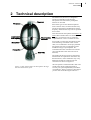
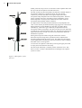
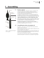
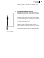
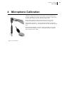
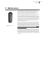
Instruction Manual
Im1212_1Ed1R1En
May 2004
Outdoor Microphone Kit
Nor1212
Instruction Manual
Im1212_1Ed1R1En
May 2004
Outdoor Microphone Kit
Nor1212
Nor1212 – User Guide
Im11212_1Ed1R1En – May 2004 edition
Norsonic is a registered trademark of Norsonic AS.
Every effort has been made to supply complete and accurate information. However, Norsonic AS assumes no
responsibility for the use of – or for the consequential damage resulting from the use of – this information and/or the
instrumentation described herein. Furthermore, Norsonic AS assumes no responsibility for any infringement of the
intellectual property rights of third parties, wherever applicable, which could result from such use.
Norsonic AS reserves the right to amend any of the information given in this manual in order to take account of new
developments.
If you wish to communicate with us, please feel welcome.
Our address is:
Norsonic AS, P.O. Box 24, N-3421 Lierskogen, Norway
e-mail: [email protected]
Find us on the web: www.norsonic.com
Copyright © Norsonic AS 2004
All rights reserved
Norsonic Nor1212
User Guide
Contents
1
Introduction......................................................................................................................................... 3
2
Technical description......................................................................................................................... 5
3
Assembling ......................................................................................................................................... 7
3.1
Devices required............................................................................................................................................................7
3.2
Assembling the outdoor microphone unit ....................................................................................................................7
3.3
Mounting on a mast ......................................................................................................................................................8
3.4
Grounding and lightening protection...........................................................................................................................9
4
Microphone Calibration ................................................................................................................... 11
5
Maintenance ...................................................................................................................................... 13
6
Specifications ................................................................................................................................... 15
6.1
Mounting direction .....................................................................................................................................................15
6.2
Acoustic performance .................................................................................................................................................15
6.2.1
Frequency response ................................................................................................................................................15
6.2.2
Directional response ...............................................................................................................................................16
6.3
General ........................................................................................................................................................................20
6.4
Accessories and spare parts ........................................................................................................................................20
1
Norsonic Nor1212
User Guide
1 Introduction
The Outdoor microphone kit Nor1212 allows the standard measurement
microphone Nor1225 with preamplifier Nor1201 or Nor1206 to be used
as an all-weather microphone for semi-permanent applications. The
Outdoor Kit protects the microphone from rain and snow, dust and
insects.
Further, the Outdoor kit improves the measurement accuracy by reducing
the wind noise and by changing the directional response of the
microphone capsule to suit vertical mounting.
The Outdoor Kit allows the Nor1225 microphone to retain its Class 1
specifications according to IEC6051 and IEC61672-1 when the weather
protection system is in place.
The acoustic sensitivity for free-field measurement microphones, like
Nor1225, is optimised for sound reaching the microphone along the axis
of symmetry. When mounted for outdoor measurements the microphone
is normally mounted with the diaphragm pointing upwards. The
microphone response will therefore be at its best for sound from above.
Even for aircraft noise monitoring, the sound will seldom approach the
microphone just from this direction. The outdoor kit has therefore been
designed to change the directional characteristics of the microphone to
improve the accuracy in other directions. The result is a microphone with
a response almost symmetrical around the horizontal plane and with a flat
random incidence response.
The Outdoor Kit allows the microphone to be calibrated with a normal
sound calibrator without the need for extra accessories. Access to the
microphone is gained by dismounting the upper part of the kit.
The outdoor kit is made of an electrical insulating material. The
microphone body will be fully insulated from the mounting mast thereby
reducing pick-up of electrical hum and noise.
3
4
Introduction
For improved protection in excessive humid applications, the outdoor kit
may be combined with a microphone desiccator or the preamplifier may
be heated.
Norsonic Nor1212
User Guide
2 Technical description
The Outdoor Kit, Nor1212, is designed to
operate in combination with Norsonic
microphone Nor1225 and the preamplifier
Nor1201 or Nor1206.
Some other types of free-field microphones
such as the Nor1223, Nor1226 and 1227 may
also be used with minor modifications of their
frequency and directional response as specified
for Nor1225.
Note that Nor1220 microphone should not to be
used with the Outdoor Kit as its uncompensated
frequency response may not be within the
requirements for a class 1 sound level meter.
If you need to connect the microphone system
to the measuring instrument with a coaxial
cable, we recommend to use the pre-polarised
microphone Nor1227 in combination with a
suitable ICP® type of preamplifier. We
recommend Nor1207 with desiccator TA202
(You need the desiccator due to the size of
Nor1207).
The outdoor kit Nor1212 protects the normal
measurement microphone Nor1225 from rain,
dust and insects, which sometimes may creep
behind the normal microphone grid. The
construction is shown on figure 2.1.
Figure 2.1 The sound reaches the microphone through
the mesh and acoustic ports.
The microphone is mounted inside a tube. The
sound enters the microphone through 12
acoustic ports placed equidistantly around the
circumference. These ports have a drip-edge to
prevent water from entering the tube. For
5
6
Technical description
further protection, the ports are covered with a water-repellent mesh. This
also prevents the microphone from dust and insects.
The tube is made of polyacetal (POM). The material is durable and has a
low thermal conductivity compared to metal. This low thermal
conductivity will have the effect of raising the temperature of the
microphone and preamplifier above the ambient temperature. This heat
gain is caused by the power consumption of the preamplifier. Even a
small temperature rise will prevent condensation of water within the
microphone during humid weather conditions.
For applications in extremely humid conductions, the preamplifier Nor
1201 or Nor1206 may be further heated by applying power to the internal
heating element. See the handbook for Nor1201 for further details.
Alternatively, a desiccator type TA202 may be placed between the
microphone and the preamplifier. The desiccator absorbs water and hence
provides dry air to the microphones back vent. The desiccator needs to be
regenerated from time to time; see section 5 for information about this
maintenance operation.
Placing the microphone inside a long rod results in the acoustic
directional response being almost symmetrical above and below the
horizontal plane through the acoustic ports. This makes the microphone
system applicable for monitoring of aircraft overhead as well as industryand traffic-sources on the ground.
Access to the microphone is achieved by removing the upper part which
is simply unscrewed from the main body.
The base of the main body is sealed by means of the base screw. This
base screw also contains a threaded hole for mounting the microphone
system on a mast.
Figure 2.2 Microphone system
Nor1212
Norsonic Nor1212
User Guide
3 Assembling
Upper part
3.1
The Nor1212 Outdoor Kit is designed to operate in combination with
Norsonic microphone Nor1225 and the preamplifiers Nor1201 or
Nor1206. The description of the assembly in this manual is based on
microphone Nor1225 and preamplifier Nor1201.
Approx. 11 cm
Microphone
with preamplifier
Fastening nut
Devices required
In addition to the outdoor kit Nor1212 you need the microphone, the
preamplifier and a cable for connection to the measuring instrument. For
Norsonic sound level meters, we recommend cable type Nor1408, which
comes in standard lengths of 5, 10, 15, 20, 30 and 50 metres – other
lengths are available on request. This cable is Teflon®-insulated and
hence absorbs very little water, which is very important in order to retain
the normal polarisation voltage for the microphone. If you need weatherprotected connectors, we recommend cable type Nor1485.
Depending on the application, you will need a mast or tripod for
mounting the microphone system and possibly also devices for proper
grounding and lightening protection. See below.
Main body
3.2
Base screw
Assembling the outdoor microphone unit
See figures 2.1, 2.2 and 3.1 for a description of the main parts of the
outdoor protection kit Nor1212.
Remove the upper protection part with the windscreen and the base screw
from the main body of the outdoor kit.
Figure 3.1 Adjusting the height of
the microphone
Mount the cable on the preamplifier. Do not mount the microphone. Put
the upper part of the preamplifier through the main body of the kit from
below. Loosen the fastening nut if necessary.
If you want to use the desiccator TA202, mount it on the preamplifier.
Mount the microphone on the desiccator or preamplifier as appropriate.
7
8
Assembling
Important!
Follow the mounting instructions
carefully; otherwise, the
microphone may be harmed!
Adjust the height of the microphone preamplifier assembly to be a
slightly higher than the centre of the windscreen, see figure 3.1.
(Approximately 11 cm). Tighten the fastening nut just enough so that the
preamplifier will not move by its own weight as the microphone will be
automatically located to the right position as the two halves are screwed
together and it is important that the force used is minimal to prevent
damage to the microphone grid. Accurate adjustment of the height of the
microphone is very important to maintain the specification for the
frequency response. Carefully screw on the upper part; this will press the
microphone downward so the top of the microphone grid is placed
accurately at the opening for the acoustic ports. Now carefully remove the
upper part in order not to alter the height of the microphone. Now tighten
the fastening nut using hand force only and do not over-tighten.
The purpose of the base screw is threefold:
Figure 3.2 The desiccator TA202
is placed between the microphone
and the preamplifier.
•
It is a base for mounting the microphone system on a mast or
tripod.
•
It closes the main body, but has a water drain to let any
condensate escape.
•
It forms a tension relief for the cable.
Press the microphone cable slightly towards the preamplifier and mount
the base crew at the lower end of the main body.
After mounting of the upper protection part, the outdoor microphone unit
will be ready for use. However, we recommend that you test the unit
together with the measuring instrument by applying a calibrator before
the upper part is mounted.
3.3
Mounting on a mast
The outdoor microphone assembly may easily be mounted on a
supporting mast that has a mounting stud suitable for connection to the
Nor1212. The dimensions are given in the section dealing with the
specification and are those commonly used on tripods for cameras.
Norsonic Nor1212
User Guide
If the mast is high and you need to make regular calibrations or other
service operations, we recommend the use a tiltable or a telescopic mast.
Norsonic can supply different masts on demand.
Fasten the microphone cable along the mast properly. A cable flapping
onto the mast in windy conditions may create excessive noise and ruin the
measurement accuracy.
3.4
Grounding and lightening protection
If the outdoor microphone assembly is the highest object in the vicinity
when mounted, it may be exposed to lightening strikes. We recommend
that the mast, if conductive, is properly grounded.
A lightening rod in proper contact with a conductive mast will form a
suitable protection against the effects of a lightening strike and a
recommended configuration is given below.. The rod should be placed at
least 25 cm to the side of the microphone assembly and have a diameter
not more than 10 mm in order not to interfere with the direction properties
of the microphone. Its height should be at least 10 cm above the tip of the
microphone assembly (the microphone is located 14 cm below the
insulated tip). If the mast is not conductive, the lightening rod should be
connected to a proper lightening conductor.
Safety considerations may require that the screen of the microphone cable
to be properly grounded. We recommend making the combined
grounding for the cable and instrument at one point only in order to
reduce the risk of pick-up of hum and electro-magnetic noise. Verify the
noise floor of the complete system after installation is completed to
ensure it is below the lower end of the required measurement range. If a
quiet location is not available, the noise floor may be measured by
substituting the microphone with a dummy microphone like Nor1448. As
an alternative the Nor1447 adaptor terminated with a short-circuit or a 50
ohm BNC termination is also a suitable device for making this test.
Figure 3.3 Lightening
protection
.
9
Norsonic Nor1212
User Guide
4 Microphone Calibration
The outdoor microphone system can be calibrated with a normal sound
calibrator without the need for special couplers. We recommend using
Nor1251 (1000 Hz) or Nor1253 (250 Hz). The procedure is valid for the
microphones Nor1223, Nor1225, Nor1226 and Nor1227.
Screw off the upper part of the protector kit to gain access to the
microphone. Mount the calibrator and switch it on. See figure 4.1.
If the calibrator frequency is 250 Hz, adjust the reading to be the level
stated for the calibrator, e.g. 124,0 dB for Nor1253 with 124 dB specified
level.
If the calibrator frequency is 1000 Hz, adjust the reading to be 0,2 dB
below the stated calibrator level, e.g. 113,8 dB for Nor1251 calibrator
with a stated level of 114 dB.
Figure 4.1 Calibration
11
12
Norsonic Nor1212
User Guide
5 Maintenance
The need for maintenance depends largely on the environmental
conditions where the microphone system is used. For most semipermanent applications, the maintenance is normally either done before
the start or after the end of a measurement. During the measurement
normally only periodic checks of the calibration are needed.
Before the start of a new measurement, remove the windscreen and verify
that it is not contaminated with dust or dirt. The windscreen may be
washed by hand using standard washing up detergents only. Ensure that it
has been thoroughly rinsed in clean water and is completely dry before it
is remounted. Do not use excessive heat for the drying: 60ºC maximum. If
used outdoor most of the time, we recommend replacing the windscreen
every other year, spare part Nor4520. However in some locations, near to
chemical complexes or in coastal installations it may be necessary to
replace the windscreen earlier.
Figure 5.1 Desiccator
TA202
Remove the upper protection part and verify that the mesh covering the
acoustic ports is clean and free from dust. You may inspect the mesh by
holding it in front of a light source; rotate the upper protection part and
look through the holes. Use a soft brush to wipe off any dust or detritus. If
heavily polluted, peel off the mesh and replace it with a new; spare part
number Norsonic 0896000. The mesh comes with an adhesive. When you
mount a new mesh, ensure that the splice is placed midway between the
acoustic ports! See figure 2.1.
If you use the desiccator, this needs to be dried at regular intervals. This
may be attained by placing the desiccator for a few hours at an elevated
temperature, e.g. 100ºC. Do not heat beyond 130ºC as this will harm the
device. The desiccator TA202 has a small window where you can see the
silica gel inside, see figure 5.1. When dry, the gel has a light blue colour.
This colour changes to milky-white when the gel is wet and cannot absorb
more water.
13
Norsonic Nor1212
User Guide
6 Specifications
6.1
Mounting direction
The microphone kit shall be mounted with the tip pointing upwards and
the axis of symmetry shall be vertical. The acoustic reference axis for the
microphone-assembly is from above, 25º from the vertical axis.
6.2
Acoustic performance
6.2.1
Frequency response
The modification of the free-field response and the random incidenceresponse of a Nor1225 microphone when placed in the outdoor kit
Nor1212 is shown on the diagram below together with the requirements
for a Class 1 sound level meter according to IEC61672-1. Both the free
field and the random incidence-response shown are referred to the freefield response for Nor1225 microphone without the protection kit.
15
16
Specifications
Correction to microphone free-field response
+5
0
-5
-10
100
200
300
500
1k
2k
3k
5k
10k
20k
Frequency [Hz]
Free-field response
Random-incidence response
Tolerance limits with uncertainty. IEC 61672-1 Class 1
6.2.2
Directional response
The directional response satisfies the requirements for a Class 1 sound
level meter according to IEC61672-1. The figures on the next pages show
the directional response in detail in a plane through the horizontal and
vertical axis of symmetry.
Norsonic Nor1212
User Guide
0o
+7 dB
-5 dB
90o
270o
-5 dB
Directional response
Horizontal plane
1k, 2k, 4k, 6.3k. 8k, 10k. 12,5k and 16kHz
+7 dB
180o
1 k, 2k, ...16kHz
17
18
Specifications
Reference
direction
0o
+7 dB
6,3 kHz
4 kHz
-5 dB
6,3 kHz
90o
270o
2 kHz
1 kHz
-5 dB
Directional response
Vertical plane
1k, 2k, 4k and 6.3kHz
+7 dB
180o
Norsonic Nor1212
User Guide
Reference
direction
0o
16 kHz
+7 dB
12,5 kHz
10 kHz
8 kHz
-5 dB
90o
270o
-5 dB
Directional response
Vertical plane
8k, 10k. 12,5k and 16kHz
+7 dB
180o
19
20
Specifications
6.3
General
Mounting thread: 3/8" UNC
Temperature range: -25ºC to +50ºC
Height: 45 cm
Diameter: Approx 5 cm with windshield
Weight: 220 g
6.4
Conformity
The device is in conformity with the following standards:
EN-50081-1
EN-50082-1
6.5
Accessories and spare parts
Desiccator: TA202
Windshield: Nor4520.
Dust-mesh: Norsonic part no 0896000.
Microphone: Nor1225
Microphone preamplifier: Nor1201, Nor1206 or Nor1207
Sound calibrator: Nor1251 or Nor1253
Microphone cable: Nor1408
Standard lengths 5, 10, 15, 20, 30 and 50 metres – other lengths on
request.
Dummy microphone: Nor1448 (18 pF) or Nor1447 with a short-circuit.
P.O.Box 24
N-3421 Lierskogen
Norway
www.norsonic.com