1
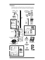
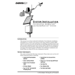
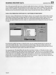
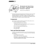
E Z-M O U N T A D V A N C E D S T A T I O N
INSTALLATION MANUAL FOR GROWEATHER®,
ENERGY ENVIROMONITOR® AND
HEALTH ENVIROMONITOR® SYSTEMS
This manual describes how to install the EZ-Mount Advanced Station.
Separate manuals included with the station cover the operation of the console
and sensors.
The EZ-Mount Advanced Stations are the “EZ” installation versions of the
GroWeather, Energy EnviroMonitor and Health EnviroMonitor stations. In
addition to the normal EZ-sensor suite, the advanced stations feature an EZSensor Arm for measuring Solar Radiation and/or UV (depending on the
station).
There are two installation options for the EZ-Mount Advanced Stations: standard and industrial. The industrial option offers greater protection from radio
frequency interference, electrostatic discharges, and voltage surges by providing 100 feet of shielded cable, an extra grounding wire, an ICAM (Interface
Cable Adapter Module) with its own grounding wire, and a 25 foot (7.5 m)
cable to connect the ICAM to the console.
STANDARD INSTALLATION
Sensor Array
Standard Sensor Interface
Module (SIM) inside Field Case
100' Standard
8-Conductor Cable
Console
INDUSTRIAL INSTALLATION
Sensor Array
Industrial Sensor Interface
Module (SIM) inside Field Case
Interface Cable
Adapter Module
(ICAM)
100' Shielded
8-Conductor Cable
Optional Alarm
Output Module
(AOM)
25' Standard
8-Conductor Cable
Console
Additional products—such as the Alarm Output Module (AOM), Mounting
Tripod, EZ-Solar Power Kit, WeatherLink®, and Grounding Kit—are mentioned here but are not required (contact Davis for more information).
Product # 7450EZ, 7455EZ, 7460EZ, 7465EZ, 7470EZ, 7475EZ (EU, UK, M)
C OMPONENTS
The EZ-Mount Advanced Weather Station includes the following components. Please make sure you have everything you need before beginning.
Anemometer
5/16" x 1-1/2"
U-Bolt
5/16" Flat Washers
5/16" Lock Washers
5/16" Hex Nuts
1-1/8"
Saddles
Wind Cups
Extension
Tube
This hardware
comes installed
on Sensor Array:
#8 x 1-1/2"
Pan HeadScrew
5/16" x 3"
Lag Screws
Cable
Tie
Allen
Wrench
5/16"
Flat Washers
#8 Lock Washer
#8 Hex Nut
EZ-Sensor Arm
Sensor Array
Rain
Collector
Cone
16.5' (5m) Ground Wire(s)
(Not Shown)
Brace Clamp
5/16"
Hex Nut
5/16" x 2"
Carriage Bolt
Debris Screen
(place inside
Rain Collector Cone
after installation)
Weather Station Console
100' (30 m) 8-Conductor Cable, Standard
(Industrial Not Shown)
Additional Components for INDUSTRIAL Installations Only
Interface
Cable
Adapter
Module
ICAM (ICAM)
Kit
8-Conductor Cable,
Standard,
for ICAM to Console,
25' (7.5m)
#8 x 3/4"
Pan Head Screws
(for mounting Console
on wall)
#6 x 1/4"
Pan Head Screws
(for mounting Console
on Field Case door)
Power Adapter
#6x1"
16.5' (5m) (25mm) Cable Adhesive
Ground Wire Screws Ties
Pads
Page 2
EZ-Mount Advanced Station
T OOLS
AND
M ATERIALS N EEDED
In addition to the components listed on page 2, you may need some of the following tools and materials.
✦ Flat-Bladed Screwdriver
✦ Phillips Screwdriver
✦ Adjustable Wrench
✦ Wire Cutter or Scissors
✦ Wire Stripper or Knife (Industrial Installation Only)
✦ Electrical Tape
✦ Cable Clips or Weather-Resistant Cable Ties (with ability to be mounted)
✦ Hammer
I NSTALLATION S TEPS
This manual takes you through the step-by-step process of installing your
weather station. These steps are indicated below, along with their page numbers for easy reference:
✦ Assemble and test the station, page 4
✦ Detach the extension tube, page 4
✦ Attach the anemometer, page 4
✦ Attach the wind cups, page 4
✦ Snip the cable tie in the rain collector, page 5
✦ Apply power to the console, page 5
✦ Attach the EZ-Sensor Arm, page 6
✦ Connect sensor array to console, page 8
✦ Check that the console and sensors are working properly, page 8
✦ Re-attach rain collector cone and unplug sensor array (or ICAM)
cable from console, page 8
✦ Install the station, page 9
✦ Choose locations for the sensor array and console, page 9
✦ Mount, secure, and ground the sensor array, pages 10 & 11
✦ Run sensor array cable (or ICAM cable) to console, page 11
✦ Industrial stations only: mount the ICAM, page 11
✦ Mount the console, page 14
If, once installed, you encounter any problems with the station, please refer to
the troubleshooting guide on page 14 or call our technical support line (510732-7814) for assistance.
Tools and Materials Needed
Page 3
G ETTING S TARTED
Follow the steps below to install your station. At various stages of this installation, you will be advised to test the system to ensure proper functioning.
1. Detach and remove the extension tube from the support tube by cutting the two black
cable ties.
2. Attach the anemometer arm to the support tube as shown below. Make sure that the
anemometer is positioned over the white field case and NOT over the black rain collector cone.
Anemometer
Anemometer Arm
Anemometer
Cable
#12 x 1-1/2"
Screw
Support Tube
Lock
Washer
Hex
Nut
Cable Tie
3. Attach the wind cups to the anemometer.
Push the wind cups onto the shaft as far as they will go, then tighten the set
screw. The cups should drop slightly and into the ideal position automatically. Spin the wind cups. If they do not spin freely, loosen the set screw and
lower the cups slightly. Repeat until the wind cups spin freely.
a. Push cups onto
stainless steel shaft
Page 4
b. Tighten set screw
with allen wrench
EZ-Mount Advanced Station
4. Detach the rain collector cone and snip the cable tie.
Detach the black rain collector cone from its base by rotating the cone
counter-clockwise until its latches line up with the latch openings in the base
and then raise the cone off. (The cone may be tightly attached to the base the
first time.) Carefully cut and remove the black cable tie which holds the bucket in
place during shipping.
Twist off the rain collector cone.
Snip the black cable tie.
Do not re-attach the rain collector cone at this point; you will need to test the
tipping bucket before you complete the installation.
5. Apply power to the station console.
To power up the console, first remove the console’s mounting base by pressing down on the large tab between the two oblong holes on the base’s
underside and pulling the base free. Plug the power adapter into the center
“Power” slot, as shown below, and then plug the other end into a 110 VAC
outlet. Once power is applied, the console should beep twice within 10 seconds if the console is working properly. (If you have the optional WeatherLink installed, the console should beep three times within 20 seconds.) The
readings will appear dashed out until you connect the sensors.
Note: If you are going to use a battery as backup, make sure that you plug in the AC power before
installing the battery. Powering up the console with the battery alone may cause the console
to lock up due to insufficient power. (Do NOT use a backup battery if you use the optional
EZ-Solar Power Kit.)
Console
Power Adapter
Base
AC Power
Outlet
Getting Started
Page 5
6. Attach the EZ-Sensor Arm to the sensor array.
For the recommended default assembly, attach the EZ-Sensor Arm to the
sensor array as shown below. If you are in the Northern Hemisphere, point
the arm south (or left if you are facing the same direction as the anemometer
arm). If you are in the Southern Hemisphere, point the EZ-Sensor Arm north
(or right).
Note: When mounted, the anemometer should always point west. If you mount the sensor array in
some other orientation, recalibrate the wind vane (see “Recalibrating the Wind Vane” on
page 12).
To attach the EZ-Sensor Arm, loosely fasten the brace clamp on the support
tube as shown. Then, while tightly holding the end of the brace clamp that
grips the support tube, insert the EZ-Sensor Arm, letting the wire drop
through the bottom gap in the brace clamp, and tighten.
West
Support Tube
EZ-SENSOR ARM POINTS SOUTH IN NORTHERN HEMISPHERE,
NORTH IN SOUTHERN HEMISPHERE
South
Brace Clamp
EZ-Sensor Arm
Alternative EZ-Sensor Arm Positioning
You may face the sensors straight up, as shown above, or you may reposition the arm and tilt the sensors to an angle of your choice (e.g., to match the
angle of a solar panel, or to maximize UV or solar radiation readings). Please
find detailed instructions on the following page.
Note: If you tilt sensors to match the angle of an EZ-Solar Power Kit, know that the solar panel is
probably optimized for winter reception; your sensors will not receive maximum readings in
the summer.
If you have a GroWeather, Davis recommends not tilting the solar radiation
sensor. The GroWeather’s ET calculations assume that the solar radiation
sensor points straight up.
Page 6
EZ-Mount Advanced Station
If you have a Health EnviroMonitor, on the other hand, Davis does recommend tilting the UV sensor. The Health’s temperature-humidity-sun-wind
index calculations assume that the UV sensor is tilted according to your latitude. Additionally, maximizing UV readings (via tilting) gives the best indication of potential health risk.
To maximize UV and/or solar radiation reception:
a. Recalibrate the anemometer to point north in the Northern Hemisphere,
south in the Southern Hemisphere (see “Recalibrating the Wind Vane”
on page 12 for instructions).
b. Position the EZ-Sensor Arm to point either east or west.
c. Tilt the sensor(s) toward the sun (south in the Northern Hemisphere,
north in the Southern Hemisphere).
Note: This alternative configuration is not standard for meteorological measurements.
Use the following rubric to determine the tilt angle for maximum readings:
✦ Maximum Readings During Spring or Fall
If you want maximum readings in the Spring or Fall, use your latitude as
the angle (that is, at 45˚ latitude, use an angle of 45˚ from vertical).
✦ Maximum Readings During Summer
If you want maximum readings in the Summer, subtract 18˚ from your
latitude to determine the correct angle (that is, at 45˚ latitude, use an
angle of 27˚ from vertical).
✦ Maximum Readings During Winter
If you want to maximize readings in the Winter, add 18˚ to your latitude
to determine the correct angle (that is, at 45˚ latitude, use an angle of 63˚
from vertical).
For greater accuracy in determining the correct angle, consult a table of the
sun’s declination over the desired time span. The best tilt angle is derived by
subtracting declination from latitude.
Getting Started
Page 7
7. Connect the sensor array field case to the console (see cover page schematic).
Standard Stations: Plug the free end of the 100’ (30 m) 8-conductor cable on
the sensor array into the jack labeled SENSOR INTERFACE underneath the
console. Then skip to step 8 below.
Industrial Stations: Connect the sensor array to the ICAM and then connect
the ICAM to the console.
Note: If you are using the optional EZ-Solar Power Kit, the ICAM and ICAM connections are
unnecessary (see the power kit manual for an alternative installation).
a. Strip 4” (10 cm) of cable jacket and shield (the grey outer covering and
foil-like inner covering) from the end of the cable.
b. Remove the cover from the ICAM by pressing down on the two tabs at
the top until you can remove the tabs from the slots.
c. Feed the wires through the ferrite bead and insert the tips of the wires
into terminal block connector C2 according to the wire colors printed on
the circuit board. (To place wires into a terminal, use a small screwdriver
to push down hard on the lever next to the terminal, insert the exposed
wire into the opening created, and release the lever.)
d. Connect the bare drain wire to the SHIELD terminal JP2, and cut off any
excess drain wire.
e. Attach the ground wire to the SHIELD terminal JP2 as well. Run the
ground wire and the shielded 8-conductor wire out through the bottom
right corner of the ICAM. Secure them with a cable tie to the cable tie
lug.
f. Plug the 25’ (7.5 m) standard 8-conductor cable into connector S7.
g. Reattach the ICAM cover.
h. Plug the free end of the 25’ (7.5 m) 8-conductor cable into the jack
labeled SENSOR INTERFACE underneath the console.
Note: Refer to the Interface Cable Adapter Module manual for illustrations and further assistance,
if necessary.
8. Check all of the readings on your display to be sure they appear correctly (i.e., not
dashed out).
Consult your user’s manual for instructions on displaying the various readings. Spin the wind cups, move the wind vane, and tip the rain bucket to
verify wind speed and direction and rainfall readings. Note that some sensor readings (e.g., barometer and 0.2 mm rain collectors) must be adjusted in
order to read correctly; specific instructions are contained in your user’s
manual.
If the console is having problems reading the sensors, consult the troubleshooting guide at the end of this manual.
9. Re-attach the rain collector cone.
10. Unplug the console end of the 8-conductor cable.
Page 8
EZ-Mount Advanced Station
I NSTALLING Y OUR S TATION
Choosing Locations for the Sensor Array and Console
The cable that connects your sensor array to your console (or ICAM) is 100 feet
(30 m) long. Choose a location where the cable can safely and reasonably connect with the console (or ICAM). Most people install the sensor array on the
roofs of their houses, on fences, or in open fields where wind flow, sunlight,
and rainfall are unobstructed by trees and nearby buildings.
Unless you plan to mount the console in the sensor array field case (keeping in
mind that you will need a power source), you should locate the console
indoors. For more accurate readings, follow these suggestions:
✦ Avoid placing console in direct sunlight.
The black casing heats up in direct sunlight. This may cause erroneous
readings and/or damage to the unit.
✦ Avoid placing the console near radiant heaters or heating/air conditioning ducts.
✦ If you are mounting the console on a wall, choose an inner or interior wall.
Avoid walls which heat up or cool down depending on the weather.
✦ To connect the console to an 8-conductor cable running inside the wall, attach the
mounting base to an empty switch box, using the two screw holes on the mounting base.
Installing Your Station
Page 9
Mounting the Sensor Array
The sensor array has been pre-assembled for easy installation. However, you
will still need to provide a solid mounting for the sensor array. Mounting hardware has been included for the most common installations (see figures below).
If you are using the optional Mounting Tripod, consult the tripod’s manual for
mounting instructions.
CAUTION:The station’s wind direction is calibrated as if the horizontal part of the anemometer arm
were pointing west. If you plan to mount the station facing a different direction, see “Recalibrating the Wind Vane” on page 12 for instructions on how to adjust the wind vane accordingly.
MOUNTING ON A FENCE
MOUNTING ON A POST
Sensor Array
Sensor Array
Support Tube
(swaged end)
Extension Tube
(see fence mounting for details)
1-1/8" Saddle
4x4
treated
post,
8' long
5/16" Flat Washer
12"
minimum
5/16" x 3" Lag Screw
Extension Tube
(21" long, no swaged end)
2' of
post
buried
Use post hole
digger, fill hole
with post hole
concrete
Note: For roof mounting, we recommend the optional Mounting Tripod. If mounting on a roof, tower, or
other elevated structure without the Tripod, be sure to consider the effects of lightning, wind
loading and vibration and design the installation accordingly.
Page 10
EZ-Mount Advanced Station
Securing and Grounding the Sensor Array
After mounting the sensor array, secure the sensor array to the extension tube
as shown below.
Sensor Array
Hex
Nuts
Lock
Washers
Flat
Washers
1-1/8"
Saddles
Extension
Tube
2-1/2"
1-1/2" x 5/16" U-Bolts;
torque until bolts dent
tubing slightly
Run the green grounding wire(s) to a proper ground such as a metal underground water main or grounding rod (as in Davis’ optional Grounding Kit).
Running the Cable from the Sensor Array to the Console (or ICAM)
To prevent fraying or cutting of the 8-conductor cable, secure the cable so it
does not whip about in the wind. Secure it to the extension tube by wrapping
electrical tape around them both. To prevent rain from running along the cable
to your console, secure the cable underneath the eaves of your house or in
another location similarly shielded from rain; place cable clips or weatherresistant cable ties approximately every 3-5 feet (1-1.6 m).
Note: Do not use metal staples or a staple gun to secure the cable. Metal staples—especially when
installed with a staple gun—have a tendency to cut the cables.
Mounting the ICAM, Industrial Stations Only
Use the hardware provided to install the ICAM in a sheltered, weatherprotected area (or a Davis weatherproof shelter). Refer to the ICAM manual for
instructions, if necessary. Remember to ground the ICAM to a proper ground
such as a metal underground water main or grounding rod (as in Davis’
optional Grounding Kit).
Installing Your Station
Page 11
Recalibrating the Wind Vane
The wind vane is pre-calibrated as if the anemometer arm were facing west. If
you choose to mount your station in a different orientation—for example, in
order to tilt the EZ-Sensor Arm for maximum readings—you need to recalibrate the wind vane. Otherwise, skip this calibration.
To recalibrate the wind vane, you will need to look at the console display. If
your EZ-Station is mounted on a roof or raised platform, you may wish to have
a friend on the ground do this for you. Or, you may wish to bring the console
onto the roof or platform with you.
1. Use the allen wrench provided to loosen the set screw on the side of the wind vane
and remove the wind vane from the shaft.
Lossen set
screw
Remove wind vane
from wind direction
shaft
2. Press WIND on the console until a wind direction reading and the word DIRECTION
appear on the display.
3. Use a compass or local area map to determine which direction (N, S, E, W, NE, etc.)
the anemometer arm is pointing.
4. Use the wind direction chart to find the
degree reading which corresponds to that
direction.
5. Slowly turn the wind direction shaft with your
fingers. Stop turning when the console display
reaches the degree reading obtained in step 4.
6. Being careful to keep the stainless steel shaft
from turning, place the wind vane on the shaft
with the bullet-shaped nose of the vane pointing in the same direction as the arm. Leave
approximately a 1/16-inch (1.5-mm) gap
between the base of the wind vane and the
arm.
0° N
315° NW
45° NE
270° W
90° E
225° SW
135° SE
180° S
WIND DIRECTION CHART
7. Use the allen wrench provided to tighten the set screw on the side of the wind vane.
Do not over-tighten.
8. Test your assembly by pointing the wind vane in any direction and—using the compass or map as a guide—make sure the console displays the correct wind direction.
Re-adjust the wind vane if necessary.
Page 12
EZ-Mount Advanced Station
Mounting the Console
1. Plug the 8-conductor cable into the SENSOR INTERFACE jack on the console.
2. Apply power to the console (step 7 on page 8).
3. Install a backup battery in the console, if desired.
If you are using the optional EZ-Solar Power Kit, do not install a backup
battery.
4. Mount the console on a desk, shelf or wall.
You can change the console’s orientation by reversing the mounting base, as
shown below.
DISPLAYING THE CONSOLE ON A DESK OR TABLE
DISPLAYING THE CONSOLE ON A SHELF
Or, to display the console on a wall, follow these steps:
a. Hold the mounting base flat against the wall and use a pencil to mark
the location of the two keyholes.
b. Use an electric drill with a #36 or 2.5-mm drill bit to make pilot holes in
these locations.
c. Using a screwdriver, drive the two pan head
screws into the wall. Leave at least 1/8 inch (3 mm)
between the wall and the heads of the screw.
d. Depending on how high you mount the console on
the wall, you can use either tabletop or shelf orientation. Attach the mounting base in the orientation
you prefer.
e. Slide the keyholes on the back of the mounting
base over the two screw heads. Lock the console
into place by gently sliding it downward.
Installing Your Station
Page 13
T ROUBLESHOOTING
While the EZ-Mount Advanced Station is designed to provide years of troublefree operation, occasional problems may arise. If you experience a problem,
please check the troubleshooting tips below before calling tech support.
✦ Console does not register any rainfall
Double check that you have cut the cable tie that secures the rain bucket
during shipping. See step 4 on page 5 for instructions. Also, make sure the
anemometer is not positioned above the rain collector cone.
✦ Console does not register wind direction correctly
Check that you have either pointed the anemometer arm westward when
mounting (page 10), or that you have recalibrated the wind vane to the
anemometer arm’s current direction.
✦ Console locks up
Insufficient power during power up or a power surge may cause the console to lock up. If this occurs, remove all power by disconnecting any battery backup and the AC/DC power cord. Wait for 1 minute with all of the
power removed. Then re-connect the AC/DC power cord and listen for 2
beeps within 10 seconds.
Note: If you have the WeatherLink installed, listen for 3 beeps within 20 seconds and then, if all
is well, try communicating with the WeatherLink using the software.
Once you receive the final beep, install a fresh backup battery, if desired,
and put the console back into service.
✦ Display is flashing
Unit is operating under battery power. Check to be sure the power adapter
has not come unplugged from the console or outlet.
✦ Display is blank
Unit is not receiving power. Check to be sure the power adapter has not
come unplugged from the console or outlet.
If power is interrupted, battery may be installed incorrectly. Check and reinstall.
Battery may be run down or old. Replace.
✦ Display shows a series of dashes in place of function reading
Sensor for function which is "dashed out" is not plugged in.
Cable from sensor for function which is "dashed out" may have broken
wire. Check the areas where cables have been secured carefully.
A reading has exceeded the limits indicated on the specifications table.
For temperature, wind speed, or rainfall: calibration numbers may be
causing readings to exceed display limits. Check calibration number and
adjust if necessary.
Page 14
EZ-Mount Advanced Station
✦ Display is sluggish or console does not work at low temperatures
The LCD display may not work below 32˚F (0˚C). Use the external temperature sensor in low-temperature locations and keep the console in a
warmer location. See “Mounting the Console” on page 13 for more information.
✦ Other problems
Check the troubleshooting guide in the back of your user’s manual and
sensor manuals for help with many of the most common problems.
If, after checking this troubleshooting guide, you are unable to solve the
problem, please call our technical support team at (510) 732-7814 for assistance
(M-F, 7 am–5:30 pm PST). Please do not return your unit for repair without
prior authorization.
One Year Limited Warranty
For details on Davis’ warranty policy, please refer to the Maintenance, Service,
and Repair Information brochure included with your station.
FCC Part 15 Class B Registration Warning
This equipment has been tested and found to comply with the limits for a
Class B digital device, pursuant to Part 15 of the FCC Rules. These limits are
designed to provide reasonable protection against harmful interference in a
residential installation. This equipment generates, uses, and can radiate radio
frequency energy and, if not installed and used in accordance with the instructions, may cause harmful interference to radio communications.
However, there is no guarantee that interference will not occur in a particular
installation. If this equipment does cause harmful interference to radio or television reception, which can be determined by turning the equipment on and
off, the user is encouraged to try to correct the interference by one or more of
the following measures:
• Reorient or relocate the receiving antenna.
• Increase the separation between the equipment and receiver.
• Connect the equipment into an outlet on a circuit different from that to which the
receiver is connected.
• Consult the dealer or an experienced radio/TV technician for help.
Changes or modifications not expressly approved in writing by Davis Instruments may void the user's authority to operate this equipment.
Troubleshooting
Page 15
Product Numbers: 7450EZ, 7455EZ, 7460EZ, 7465EZ, 7470EZ, 7475EZ (EU, UK, M)
Davis Instruments Part Number: 7395-305
EZ-Mount Advanced Station Installation Manual for GroWeather®, Energy EnviroMonitor® and Health
EnviroMonitor® Systems
Rev. A Manual (7/8/99)
Controlled online: Weather Manuals/Consoles/EZ/EZ-Adv
This product complies with the essential protection requirements of the EC EMC Directive 89/336/EC.
© Davis Instruments Corp. 1998. All rights reserved.
3465 Diablo Avenue, Hayward, CA 94545-2778
510-732-9229 • Fax: 510-732-9188
E-mail: [email protected] • www.davisnet.com