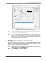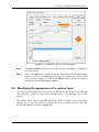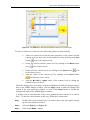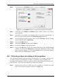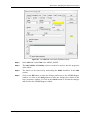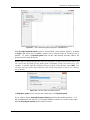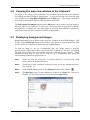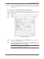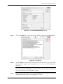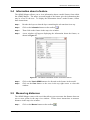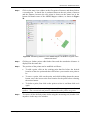
1
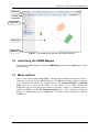
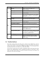
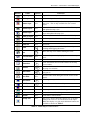
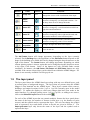
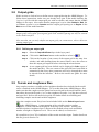
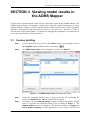
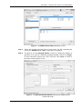
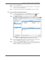
ADMS Mapper User Guide CERC ADMS Mapper User Guide Version 2.0 October, 2013 Cambridge Environmental Research Consultants Ltd. 3, King’s Parade Cambridge CB2 1SJ UK Telephone: +44 1223 357773 Facsimile: +44 1223 357492 Email: [email protected] Web site: http://www.cerc.co.uk Contents SECTION 1 Introduction to the ADMS Mapper............................................................ 3 1.1 Overview of the ADMS Mapper.................................................................................. 3 1.2 Launching the ADMS Mapper..................................................................................... 4 1.3 Menu options................................................................................................................ 4 1.4 Toolbar buttons ............................................................................................................ 5 1.5 The layer panel............................................................................................................. 7 1.5.1 Showing and hiding layers ................................................................................. 8 1.5.2 Reordering layers ............................................................................................... 8 1.6 The map view window................................................................................................. 8 1.7 Coordinate systems ...................................................................................................... 9 SECTION 2 Setting up a run using the ADMS Mapper .............................................. 11 2.1 Viewing existing sources, buildings, specified output points, the output grid, terrain and roughness files................................................................................................... 11 2.2 Point and jet sources .................................................................................................. 11 2.2.1 Adding a point or jet source ............................................................................. 11 2.2.2 Moving a point or jet source ............................................................................ 12 2.2.3 Deleting a point or jet source ........................................................................... 12 2.3 Line and road sources ................................................................................................ 12 2.3.1 Adding a line or road source ............................................................................ 13 2.3.2 Editing a line or road source ............................................................................ 13 2.3.3 Moving a line or road source............................................................................ 14 2.3.4 Deleting a line or road source .......................................................................... 14 2.4 Area and volume sources ........................................................................................... 14 2.4.1 Adding an area or volume source..................................................................... 15 2.4.2 Editing an area or volume source..................................................................... 15 2.4.3 Moving an area or volume source .................................................................... 16 2.4.4 Deleting an area or volume source................................................................... 16 2.5 Grid sources and aircraft sources ............................................................................... 16 2.6 Buildings .................................................................................................................... 17 2.6.1 Adding a rectangular building.......................................................................... 17 2.6.2 Adding a circular building................................................................................ 17 2.6.3 Editing a rectangular building .......................................................................... 18 2.6.4 Editing a circular building................................................................................ 18 2.6.5 Moving a building ............................................................................................ 18 2.6.6 Deleting a building ........................................................................................... 19 2.7 Specified output points............................................................................................... 19 2.7.1 Adding an output point..................................................................................... 19 2.7.2 Moving an output point .................................................................................... 20 2.7.3 Deleting an output point................................................................................... 20 2.7.4 Viewing points in an *.asp file......................................................................... 20 2.8 Output grids................................................................................................................ 21 2.8.1 Defining an output grid .................................................................................... 21 2.9 Terrain and roughness files ........................................................................................ 21 SECTION 3 Viewing model results in the ADMS Mapper.......................................... 23 3.1 Contour plotting ......................................................................................................... 23 3.2 Contour plotting using third party software............................................................... 24 ADMS Mapper User Guide Page 1 SECTION 1 –Introduction to the ADMS Mapper 3.2.1 3.2.2 Contour plotting using Surfer........................................................................... 24 Contour plotting using Spatial Analyst ............................................................ 26 SECTION 4 Modifying the appearance of layers ......................................................... 29 4.1 Modifying the transparency of a layer ....................................................................... 29 4.2 Modifying the appearance of a marker layer ............................................................. 30 4.3 Modifying the appearance of a line layer................................................................... 31 4.4 Modifying the appearance of an area layer ................................................................ 32 4.5 Modifying the appearance of a contour layer ............................................................ 33 4.6 Colouring a layer according to its properties ............................................................. 35 4.7 Displaying feature names........................................................................................... 39 SECTION 5 Additional features..................................................................................... 41 5.1 Setting the coordinate system .................................................................................... 41 5.2 Copying the map view window to the clipboard ....................................................... 43 5.3 Displaying background images.................................................................................. 43 5.3.1 Setting the coordinate system for a background layer ..................................... 44 5.4 Information about a feature........................................................................................ 46 5.5 Measuring distances................................................................................................... 46 5.6 Viewing features in 3D .............................................................................................. 48 5.7 Export features ........................................................................................................... 48 5.7.1 Exporting to Google Earth ............................................................................... 49 ADMS Mapper User Guide Page 2 SECTION 1 –Introduction to the ADMS Mapper SECTION 1 Introduction to the ADMS Mapper 1.1 Overview of the ADMS Mapper The ADMS Mapper is a visualisation and editing tool for the ADMS models which allows model items to be created, edited and displayed graphically. The features available in the ADMS Mapper vary depending on which model it is being used with; for example, some features are available across all models and some features are specific to ADMS-5, ADMS-Urban, ADMS-Roads, or ADMS-Airport. The ADMS Mapper can be used to create, edit and display the following model items: Point, jet, line, area, volume and road sources, Buildings, Specified point receptors, Regular Cartesian output grids. Additionally, Grid sources and aircraft sources can be displayed, Specified points given in an *.asp file can be displayed, Terrain and roughness files can be visualised, A background map can be added to the ADMS Mapper view so that the geometry of an item can be changed using the map as a guide, ADMS output data can also be displayed in the ADMS Mapper by using the Contour Plotter, A 3D visualisation of the features can be made. Instructions on how to launch the ADMS Mapper are in Section 1.2. Figure 1 shows the ADMS Mapper with the main features labelled. The options available from the menu are described in Section 1.3 and the buttons available on the toolbar are discussed in Section 1.4. The remaining parts of the ADMS Mapper, the layer panel and the map view window, are discussed in Sections 1.5 and 1.6 respectively. Instructions on how to set the coordinate system in the ADMS Mapper are given in Section 1.7. Following this introduction, Section 2 describes how to set up a run using the ADMS Mapper; Section 3 explains how to view model results in the ADMS Mapper; Section 4 describes how to modify the appearance of a layer; finally Section 5 deals with additional items such as importing background images, visualising input in 3D and exporting to Google Earth, together with other advanced features. ADMS Mapper User Guide Page 3 SECTION 1 –Introduction to the ADMS Mapper Menu bar Toolbar Layer Panel Map view Status bar Figure 1 - The ADMS Mapper with the main features labelled. 1.2 Launching the ADMS Mapper To launch the ADMS Mapper, select the ADMS Mapper option on the Utilities menu of the model interface. 1.3 Menu options There are two main menus: File and Edit. The File menu includes options to save layers, export layers, and to exit the ADMS Mapper. The Edit menu allows copying of images to the clipboard and allows any changes made to the Sources, Buildings and Specified points layers to be saved to the model. It also allows you to define whether the coordinates are part of a known projected or geographic system, e.g. Ordnance Survey OSGB coordinates, via the Set Coordinate System option – this is described further in Section 1.7. Additionally there is a Help menu. The menu options available are outlined in Table 1. ADMS Mapper User Guide Page 4 SECTION 1 –Introduction to the ADMS Mapper Menu File Option Add Layer Use Allows a layer to be added, e.g. a background map. Remove Layer Removes a layer from the map view. Export Layer… Allows the selected layer to be exported in various formats. Save layer options Saves the current appearance of the ADMS layers (colour, symbol etc.) as the default appearance. Close Closes the ADMS Mapper. Save Edits Saves the edits made to the model. Copy Map To Clipboard Copies the current view in the map window to the clipboard. Copy Legend To Clipboard Copies the layer panel to the clipboard. Copy Scalebar To Clipboard Copies the scalebar to the clipboard. Use the ADMS coordinate system Sets the coordinate system used in the ADMS Mapper to the same as that defined in the ADMS interface. Set map coordinate system This allows you to set the coordinate system to a projected or a geographic system, or to turn off the coordinate system. User Guide Opens the ADMS Mapper User Guide. About ADMS Mapper Displays information about the ADMS Mapper, e.g. version number and CERC contact details. Edit Help Table 1 - Menu options in the ADMS Mapper. 1.4 Toolbar buttons The toolbar contains buttons that allow layers, features in the ADMS layers, and the map view to be edited, as well as providing access to the Contour Plotter. The purpose of each of the buttons is summarised in Table 2 and Table 3. The remaining sections then illustrate how these are used to view, create and edit data. As the cursor is moved across the toolbar, explanations appear in the status bar at the bottom of the ADMS Mapper window explaining the function of each button. When using a tool that requires the user to specify a location in the map view window, the appearance of the cursor will change. ADMS Mapper User Guide Page 5 SECTION 1 –Introduction to the ADMS Mapper Button Name Cursor Function Export Layer N/A Export the current layer to a file. Add Layer N/A Add a new layer from a file. Remove layer N/A Remove the selected layer from the layer panel and map view. This is only available for user created layers. Refresh Layers N/A Obtain the latest data from the model for all the layers and update the map view. Refresh Layer N/A Obtain the latest data from the model for the selected layer and updates the map view. Zoom To Layers N/A Set the map view to show all the data in all the layers. Zoom To Layer N/A Set the map view to the extent of the selected layer. Zoom In N/A Zoom in. Zoom Out N/A Zoom out. Zoom Zoom to display an area defined by the user by clicking and dragging the cursor. Pan Move the map view without altering the scale. Previous Extent N/A Return to the previously displayed extent in the map view. Next Extent N/A Go to the next extent in the map view window. Information View information about a model feature in the map view window. Measure Measure the distance between two or more points in the map view window. Add Feature Add a feature to the selected layer, e.g. a point, a polygon etc. Save Edits N/A Save the edits made during the current session to the model. Edit Feature Edit the geometry of a feature in the selected layer. Shift Feature Move a feature in the selected layer. Delete Feature N/A Delete the selected feature. Undo N/A Undo a previous action while editing. Redo N/A Redo an action while editing. Contour N/A Launch the Contour Plotter. Change view N/A This icon is shown when the current view is 2D and changes the view to a 3D visualisation of the input. When the display is in 3D mode additional buttons are available as shown in Table 3. Table 2 - ADMS Mapper toolbar buttons ADMS Mapper User Guide Page 6 SECTION 1 –Introduction to the ADMS Mapper Button Name Change view Cursor N/A Function This icon is shown when the current view is 3D and changes the view to a 2D visualisation of the input. Camera position Changes the camera pan mode so that the camera position is changed by yaw and pitch rotations. Use the drop down arrow to change the mode. Camera XYZ Changes the camera pan mode so that the camera position is changed by vertical translations and left-toright horizontal translations. Camera XY Changes the camera pan mode so that the camera position is changed by left-to-right and forward-andbackward translations in the horizontal plane. Camera rotation Changes the camera pan mode so that the camera position is changed by point-of-view rotation. Sun position Changes the light and shade of the display. Zoom Zoom in and out. Table 3 - ADMS Mapper toolbar buttons for 3D display The Add Feature button will change appearance depending on the layer currently selected. For the Buildings layer, the appearance of the Add Feature button depends on the shape of the building to be added; this can be changed using the drop down arrow to the right of the button. The Contour button will change appearance depending on which contour plotting option is chosen; again this can be changed using the drop down arrow to the right of the button. Some of the buttons are only available under certain conditions; for instance, the Add Feature, Edit Feature and Shift Feature buttons are only available if the current selected layer can be edited from within the ADMS Mapper. If a button is not currently available it will be greyed out. 1.5 The layer panel The layer panel shows the ADMS data layers along with any user defined layers, such as contour plots or background images. The layers that are present when the ADMS Mapper is first launched are the ADMS layers. These layers contain all the sources, buildings, and output locations for the *.apl or *.upl file currently open in the model interface. To update the display to reflect any changes that have been made in the model interface, e.g. through opening a new *.apl or *.upl file, or adding a new source, click on the Refresh All Layers button on the toolbar. For each of the ADMS layers that can contain multiple features the layer panel shows the name of the layer, the number of features in that layer (e.g. the number of point sources) and the symbol used to represent that layer. The user can change the symbol used to represent a layer and details of how to do this are given in Section 4. The Output grid extent layer only shows the name of the layer and the symbol used to represent the layer. ADMS Mapper User Guide Page 7 SECTION 1 –Introduction to the ADMS Mapper The number displayed in the layer panel provides a handy count of the number of sources of each type that have been entered into the interface. User defined layers are either contours generated using the Contour button or background images added using the Add Layer button . Any user defined layers can be removed by first selecting the layer and then clicking on the Remove Layer button . Details about creating contour layers can be found in Section 3 and instructions for adding a background map as a layer can be found in Section 5.3. 1.5.1 Showing and hiding layers If a layer is visible then the data contained in that layer are shown in the map view window. A layer can be hidden by unchecking the checkbox next to the layer name. To make the layer visible again recheck the checkbox. 1.5.2 Reordering layers The ordering of the layers in the layer panel determines the order in which they are shown in the map view window. Features from layers at the top of the layer panel are shown on top of features from layers further down and thus may hide them from view. To reorder the layers within the layer panel click on the layer you wish to move, holding down the mouse button move it to its new position, and then release the mouse button. The symbol used to represent a layer can be made partially transparent to allow features in layers below them to be seen. See Section 4 for more details on making layers transparent. 1.6 The map view window The map view window is where the data from the current visible layers are shown. Both the ADMS and user-defined layers are shown in this window. The scale of the map view window is given as a scalebar on the toolbar and as a numerical scale on the right hand side of the status bar. The position of the cursor in the map view window is given in meters on the status bar. The scale and extent of the map view window is controlled by various toolbar buttons: To zoom and centre the window on the features of all the layers click on the Zoom To Layers button on the toolbar. To zoom and centre the window on the features of the current selected layer click on the Zoom To Layer button on the toolbar. To zoom in to a central point in the map view window click on the Zoom In button on the toolbar. To zoom out from a central point on the map view window click on the Zoom Out button on the toolbar. ADMS Mapper User Guide Page 8 SECTION 1 –Introduction to the ADMS Mapper To view a selected region in the map view window click on the Zoom button on the toolbar. Click in the top left corner of the region you want to view, and while holding down the mouse button move the cursor to the bottom right corner of the region you want to view, then release the mouse button to set the extent of the map view window. To move the view in the map view window without altering the scale click on the Pan button on the toolbar. Then click and drag the mouse in the map view window to move the view. To return to a previous viewing extent in the map view window click on the Previous Extent button on the toolbar. To go to the next viewing extent in the map view window click on the Next . This option is only available after the Previous Extent button on the toolbar Extent button has been used. 1.7 Coordinate systems There is an option to set the coordinate system within the ADMS Mapper. The choice of the coordinate system affects the way the ADMS layers are shown in the ADMS Mapper map view window. Note that the coordinate system must be selected before certain features of the ADMS Mapper can be used; for example, before exporting ADMS Mapper files to *.kml files for use in Google Earth. Coordinate systems can also be defined separately for each layer. This is a useful way of ensuring that additional features, such as background maps, use the same coordinate system as the ADMS layers. The coordinate systems for the ADMS layers should not be changed in the ADMS Mapper – these are set in the model interface, see the ADMS User Guide for more details. Full details of how to set the coordinate system are given in Section 5.1. ADMS Mapper User Guide Page 9 SECTION 2 –Setting up a run using the ADMS Mapper ADMS Mapper User Guide Page 10 SECTION 2 –Setting up a run using the ADMS Mapper SECTION 2 Setting up a run using the ADMS Mapper This section outlines how to use the ADMS Mapper to view, create and modify the geometry of the model data. The model data that can be manipulated with the ADMS Mapper varies depending on which model it is being used with, but include sources, buildings, specified output points, regular Cartesian output grids and terrain and roughness files. To view existing data from an *.apl or *.upl file refer to Section 2.1; or to add, modify the geometry of, move, or delete a feature refer to the instructions in Sections 2.2 to 2.9. 2.1 Viewing existing sources, buildings, specified output points, the output grid, terrain and roughness files To view existing sources, buildings, specified output points and the output grid, first open the *.apl or *.upl file in the model interface. Then return to the ADMS Mapper and click on the Refresh Layers button on the toolbar. To view buildings, the Buildings option must be selected in the model interface Setup screen. To view specified output points, the output type on the Grids screen of the model interface must be set to Specified points or Both. To view an output grid, the output type must be set to Gridded or Both, the coordinate system must be Cartesian and the output grid spacing Regular on the Grids screen of the model interface. To view complex terrain or surface roughness, the complex terrain option must be selected in the model interface Setup screen and either the terrain file path or roughness file path must be selected and given in the Complex terrain screen in the model interface. For details of how to set these options see the model user guide. 2.2 Point and jet sources This section covers how to add, move or delete point or jet sources using the ADMS Mapper. To follow these instructions, make sure you already have the *.apl or *.upl file which is to be edited open in the model interface, i.e. the file to which you wish to add, move or delete point or jet sources. Also make sure that the ADMS Mapper is open. 2.2.1 Adding a point or jet source Step 1 Select the appropriate layer in the layer panel e.g. the Point sources layer. Step 2 Click on the Add Feature button on the toolbar to select it. Step 3 Click in the map view window at the location where you want the source to be placed. Step 4 A new source of the appropriate type is created and displayed in the Source screen of the model interface. The source coordinates have been ADMS Mapper User Guide Page 11 SECTION 2 –Setting up a run using the ADMS Mapper filled in automatically but you will need to fill in the other parameters for the source. Refer to the model user guide for further details. Step 5 Repeat this process to add further sources of this type. 2.2.2 Moving a point or jet source Follow these steps to change the location of an existing point or jet source from within the ADMS Mapper. Step 1 Select the appropriate layer in the layer panel e.g. the Point sources layer. Step 2 Click on the Shift Feature button on the toolbar to select it. Step 3 Click on the appropriate source, and while holding down the mouse button move the cursor to the new location for the source before releasing the mouse button. Step 4 Click on the Save Edits button on the toolbar to save the changes to the model. Step 5 Repeat this process to move other sources of this type. 2.2.3 Deleting a point or jet source Follow these steps to delete an existing point or jet source from within the ADMS Mapper. Step 1 Select the appropriate layer in the layer panel e.g. the Point Source layer. Step 2 Click on the Edit Feature button on the toolbar to select it. Step 3 Select the source you want to delete by clicking on it in the map view window. The selected source will have a red dot on it; all of the other sources in that layer will have yellow dots. Step 4 Click on the Delete Feature button on the toolbar. Step 5 This will bring up a dialogue box asking if you are sure you wish to delete the feature. Click Yes to delete the source. Step 6 Click on the Save Edits button on the toolbar to save the changes to the model. Step 7 Repeat this process to delete further sources of this type. 2.3 Line and road sources This section outlines how to add, move, edit or delete road line sources using the ADMS Mapper. To follow these instructions, make sure you already have the *.apl or *.upl file to which sources are to be added, edited or deleted open in the model interface. Also make sure that the ADMS Mapper is open. ADMS Mapper User Guide Page 12 SECTION 2 –Setting up a run using the ADMS Mapper Remember that line sources must have precisely two vertices in ADMS 5 2.3.1 Adding a line or road source Step 1 Select the Line sources or Road sources layer in the layer panel Step 2 Click on the Add Feature button on the toolbar to select it. Step 3 Click in the map view window on the location of first vertex of the road or line source. Step 4 For a road source, in the map view continue to click on the location of each vertex to define multiple vertices along the road. Double click to define the final vertex of the road source. If the ADMS Mapper is being used with a *.upl file then a line source can be added in exactly the same way. If the ADMS Mapper is being used with a *.apl file then a line source can have only two vertices, and so you must double click when defining the second and final vertex. Step 5 A new road or line source has been created and is displayed in the Source screen in the model interface. The source geometry has been filled in automatically but you will need to fill in the other parameters for the source. Refer to the model user guide for further details. Step 6 Repeat this process to add further sources of these types. 2.3.2 Editing a line or road source Step 1 Select the Line sources or Road sources layer from the layer panel. Step 2 Click on the Edit Feature button on the toolbar to select it. Step 3 Select the line or road source you wish to edit by clicking on it in the map view window. Step 4 Click on the vertex you wish to move to select it, and while holding down the mouse button, move the cursor to the new location of this vertex before releasing the mouse button. When editing a road or line source the new position of the selected line source appears as a dashed line. The vertices of all the line sources appear as coloured square boxes. The vertices of the selected line source are green or red and those of the other sources are yellow. Step 5 Repeat this for the other vertex if required. Step 6 Click on the Save Edits button on the toolbar to finish editing this line source and save the changes to the model. Step 7 Repeat this process to edit other line or road sources. ADMS Mapper User Guide Page 13 SECTION 2 –Setting up a run using the ADMS Mapper 2.3.3 Moving a line or road source Follow these steps to change the location of an existing line or road source without altering the relative positions of its vertices. Step 1 Select the Line sources or Road sources layer in the layer panel. Step 2 Click on the Shift Feature button on the toolbar to select it. Step 3 Click on the appropriate line or road source, and while holding down the mouse button, move the cursor to the new location for the source before releasing the mouse button. Step 4 Click on the Save Edits button on the toolbar to save the changes to the model. Step 5 Repeat this process for all the line or road sources you wish to move. 2.3.4 Deleting a line or road source Step 1 Select the Line sources or Road sources layer in the layer panel. Step 2 Click on the Edit Feature button on the toolbar to select it. Step 3 Select the line or road source you wish to delete by clicking on it in the map view window. The vertices of the selected line source will appear as red or green dots and the vertices of the other line sources will appear as yellow dots. Step 4 Click on the Delete Feature button on the toolbar. Step 5 This will bring up a dialogue box asking if you are sure you wish to delete the feature. Click Yes to delete the source. Step 6 Click on the Save Edits button on the toolbar to save the changes to the model. Step 7 Repeat this process for all the line or road sources you wish to delete. 2.4 Area and volume sources This section outlines how to add, move, edit or delete area and volume sources using the ADMS Mapper. To follow these instructions, make sure you already have open in the model interface the *.apl or *.upl file to which sources are to be added, edited or deleted. Also make sure that the ADMS Mapper is open. Remember that area and volume sources must have between 3 and 50 vertices and be convex in shape. ADMS Mapper User Guide Page 14 SECTION 2 –Setting up a run using the ADMS Mapper 2.4.1 Adding an area or volume source Select the appropriate source layer in the layer panel e.g. the Area Step 1 sources layer. Step 2 Click on the Add Feature button on the toolbar to select it. Step 3 Click in the map view window on the location of first vertex of the source. Step 4 Click on the map view window for the locations of the rest of the vertices of the source in order, either clockwise or anticlockwise around the source. Double click when placing the last vertex to finish defining the source. As the source is defined its outline will appear as a dashed line. Step 5 A new source of the appropriate type has been created and is displayed in the Source screen in the model interface. The source geometry has been filled in automatically but you will need to fill in the other parameters for the source. Refer to the model user guide for further details. Step 6 Repeat this process to add further sources of this type. 2.4.2 Editing an area or volume source Step 1 Select the appropriate source layer from the layer panel, e.g. the Area sources layer. Step 2 Click on the Edit Feature button on the toolbar to select it. Step 3 Click on the source you wish to edit in the map view window. Step 4 Now edit the vertices of the source using the following procedures. To add a vertex, click on the existing vertex that lies before the new vertex you wish to add and then click on the location of the new vertex. To move a vertex, click on the vertex you wish to move, and while holding down the mouse button, move the cursor to the new location for this vertex before releasing the mouse button. To delete a vertex, click on the vertex you wish to delete in order to select it, and then click on that vertex again. The modified shape of the selected source will appear as a dashed line during editing. The vertices of all the sources of the selected type will appear as coloured dots. The vertices of the selected source will be green with the current selected vertex red. The vertices of the other sources of this type will be yellow. Step 5 Click on the Save Edits button on the toolbar to finish editing this source and save the changes to the model. ADMS Mapper User Guide Page 15 SECTION 2 –Setting up a run using the ADMS Mapper Step 6 Repeat this process for all the sources of this type you wish to edit. 2.4.3 Moving an area or volume source Follow these steps to change the location, without altering the shape, of an existing area or volume source using the ADMS Mapper. Step 1 Select the appropriate source layer in the layer panel, e.g. the Area sources layer. Step 2 Click on the Shift Feature button on the toolbar to select it. Step 3 Click on the appropriate source, holding down the mouse button move the cursor to the new location for this source and then release the mouse button. Step 4 Click on the Save Edits button on the toolbar to save these changes to the model. Step 5 Repeat this process for all the sources of the selected type you wish to move. 2.4.4 Deleting an area or volume source Step 1 Select the appropriate source layer in the layer panel e.g. the Area sources layer. Step 2 Click on the Edit Feature button on the toolbar to select it. Step 3 Select the source you wish to delete by clicking on it in the map view window. The vertices of the selected source will appear as red or green dots and the vertices of the other sources in this layer will appear as yellow dots. Step 4 Click on the Delete Feature button on the toolbar. Step 5 This will bring up a dialogue box asking if you are sure you wish to delete the feature. Click Yes to delete the source. Step 6 Click on the Save Edits button on the toolbar to save these changes to the model. Step 7 Repeat this process to delete further sources of this type. 2.5 Grid sources and aircraft sources Grid sources and aircraft sources can be displayed in the ADMS Mapper, but they can only be added, edited or deleted in the model interface. To view a grid or aircraft source add the source in the model interface following the instructions in the ADMS-Urban or ADMS-Airport User Guide. In the ADMS Mapper click on the Refresh Layers button ADMS Mapper User Guide . The sources will now be displayed. Page 16 SECTION 2 –Setting up a run using the ADMS Mapper 2.6 Buildings This section outlines how to add, move, edit or delete buildings using the ADMS Mapper. To follow these instructions, make sure you already have open in the model interface the *.apl or *.upl file to which buildings are to be added, edited or deleted. Make sure that the ADMS Mapper is also open. Also make sure that the Buildings option is selected in the Setup screen of the model interface. Rectangular buildings must consist of 4 vertices and be rectangular in shape. If the shape entered is not rectangular but is convex and has 4 vertices then the ADMS Mapper will convert the shape to be rectangular. The main building will be shown with a red outline. See the ADMS User Guide for more details about setting the main building. 2.6.1 Adding a rectangular building Step 1 Select the Buildings layer from the layer panel. Step 2 Use the drop down arrow on the Add Feature button on the toolbar to select Polygon and then click on this button to select it. Step 3 Click in the map view window on the locations of the four vertices of the building in order, either clockwise or anticlockwise. Double click when placing the last vertex to finish defining the building. Step 4 A new building will have been created and is displayed in the Buildings screen in the model interface. Enter the rest of the parameters for this building and then exit the Buildings screen. See the model user guide for more details. Step 5 Repeat this process to add further rectangular buildings. 2.6.2 Adding a circular building Step 1 Select the Buildings layer from the layer panel. Step 2 Use the drop down arrow on the Add Feature button on the toolbar to select Circle then click on the button to select it. Step 3 Click in the map view window on the location of the centre of the building, holding down the mouse button move the cursor until the circle is of the appropriate diameter and then release the mouse button. Step 4 A new building will have been created and is displayed in the Buildings screen in the model interface. Enter the rest of the parameters for this building and then exit the Buildings screen. See the model user guide for more details. Step 5 Repeat this process to add further circular buildings. ADMS Mapper User Guide Page 17 SECTION 2 –Setting up a run using the ADMS Mapper 2.6.3 Editing a rectangular building Step 1 Select the Buildings layer from the layer panel. Step 2 Click on the Edit Feature button on the toolbar to select it. Step 3 Select the rectangular building whose geometry you wish to alter in the map view window. The vertices of the selected building will appear as red or green dots and the vertices of the other buildings will appear as yellow dots. Step 4 For each vertex you want to move, click on that vertex, and while holding down the mouse button, move the cursor to the new location of that vertex before releasing the mouse button. Step 5 Click on the Save Edits button on the toolbar to finish editing this building and save the changes to the model. Step 6 Repeat this process to edit the geometry of further rectangular buildings. 2.6.4 Editing a circular building Step 1 Select the Buildings layer from the layer panel. Step 2 Click on the Edit Feature button on the toolbar to select it. Step 3 Select the circular building whose geometry you wish to alter in the map view window. The outline of the selected building will appear as a series of green or red dots, the other buildings will have yellow dots. Step 4 Click in the map window on the location of the centre of the new location for the building, and while holding down the mouse button, move the cursor until the circle is of the required diameter before releasing the mouse button. Step 5 Click on the Save Edits button on the toolbar to save the changes to the model. Step 6 Repeat this process to edit the geometry of further circular buildings. 2.6.5 Moving a building Follow these instructions to use the ADMS Mapper to change the location of an existing building, either rectangular or circular, without altering its shape. Step 1 Select the Buildings layer in the layer panel. Step 2 Click on the Shift Feature button on the toolbar to select it. Step 3 Click on the building you wish to move, and while holding down the mouse button, move the cursor to the new location of this building before releasing the mouse button. ADMS Mapper User Guide Page 18 SECTION 2 –Setting up a run using the ADMS Mapper Step 4 Click on the Save Edits button on the toolbar to save the changes to the model. Step 5 Repeat this process to move other buildings. 2.6.6 Deleting a building Step 1 Select the Buildings layer in the layer panel. Step 2 Click on the Edit Feature button on the toolbar to select it. Step 3 Select the building you wish to delete by clicking on it in the map view window. The vertices of the selected building will appear as red or green dots and the vertices of the other buildings will appear as yellow dots. Step 4 Click on the Delete Feature button on the toolbar. Step 5 This will bring up a dialogue box asking if you are sure you wish to delete the feature. Click Yes to delete the building. Step 6 Click on the Save Edits button on the toolbar to save the changes to the model. Step 7 Repeat this process to delete further buildings. 2.7 Specified output points In this section we look at how to add, move or delete specified output points using the ADMS Mapper. To follow these instructions, make sure you already have open in the model interface the *.apl or *.upl file to which sources are to be added, edited or deleted. Also make sure that the ADMS Mapper is open. Also ensure that the output type is set to either Specified Points or Both in the Grids screen of the model interface. 2.7.1 Adding an output point Step 1 Select the Specified Points layer from the layer panel. Step 2 Click on the Add Feature button on the toolbar to select it. Step 3 Click on the location in the map view window where you wish to place the specified output point. Step 4 A new specified output point has been created and is displayed in the Grids screen of the model interface. The X and Y (or R and Theta) coordinates have been automatically entered but the rest of the parameters need to be filled in. See the model user guide for more details. Step 5 Repeat this process to add further specified output points. ADMS Mapper User Guide Page 19 SECTION 2 –Setting up a run using the ADMS Mapper 2.7.2 Moving an output point Step 1 Select the Specified Points layer from the layer panel Step 2 Click on the Shift Feature button on the toolbar to select it. Step 3 Click on the specified output point you wish to move, and while holding down the mouse button, move the cursor to the new location for the specified output point before releasing the mouse button. Step 4 Click on the Save Edits button on the toolbar to save the changes to the model. Step 5 Repeat this process for all the specified output points you wish to move. 2.7.3 Deleting an output point Step 1 Select the Specified points layer from the layer panel. Step 2 Click on the Edit Feature button on the toolbar to select it. Step 3 Select the specified output point to delete by clicking on it in the map view window. The selected specified output point will have a red dot on it; all of the other specified output points will have yellow dots. Step 4 Click on the Delete Feature button on the toolbar. Step 5 This will bring up a dialogue box asking if you are sure you wish to delete the feature. Click Yes to delete the specified output point. Step 6 Click on the Save Edits button on the toolbar to save the changes to the model. Step 7 Repeat this process to delete further specified output points. 2.7.4 Viewing points in an *.asp file If you wish to add a large number of specified points you can do this quickly by including an *.asp file to define their locations. Refer to your model user guide for instructions on how to do this. The locations of the specified points defined in the *.asp file can be viewed in the ADMS Mapper by following these steps. Step 1 Add the file path for the *.asp file to the model interface, refer to the model user guide for instructions on how to do this. Step 2 In the ADMS Mapper click on the Refresh Layers button specified points in the *.asp file will now be displayed. . The The specified points in the *.asp file cannot be edited or deleted using the ADMS Mapper; this can be done only by editing the *.asp file directly. ADMS Mapper User Guide Page 20 SECTION 2 –Setting up a run using the ADMS Mapper 2.8 Output grids In this section we look at how to define a new output grid using the ADMS Mapper. To follow these instructions, make sure you already have open in the model interface the *.apl or *.upl file with the output grid you wish to redefine, and ensure that the ADMS Mapper is also open. Also ensure that the output type is set to either Gridded or Both, the co-ordinate system is set to Cartesian and the output grid spacing set to Regular in the Grids screen of the model interface. You can only define a regular Cartesian output grid using the ADMS Mapper. Polar output grids with regular spacing and grids with variable spacing can only be entered in the model interface. Also note that you can only redefine an output grid, you cannot move, edit or delete an existing output grid. 2.8.1 Defining an output grid Step 1 Select the Output Grid Extent layer in the layer panel. Step 2 Click on the Add Feature button on the toolbar to select it. Step 3 Click on the location of one corner of the output grid in the map view window, and while holding down the mouse button, move the cursor to draw the output grid required before releasing the mouse button. Step 4 A new output grid has been defined and is displayed in Grids screen of the model interface. The new extent of the grid will have been filled in automatically but if any other parameters need to be changed these must be altered from the interface. Refer to the model user guide for more details. 2.9 Terrain and roughness files Any complex terrain or variable surface roughness that has been included in the model can be visualised in the ADMS Mapper. To view this data in the ADMS Mapper, first make sure that the complex terrain option has been selected in the model interface and that either the terrain file path (*.ter) or the roughness file path (*.ruf) has been selected and specified. Refer to the model user guide for further details on modelling and including complex terrain and variable roughness. After the complex terrain file(s) have been included click on the Refresh Layers button in the ADMS Mapper. A representation of the variable terrain or surface roughness, or both, will then be displayed in the map view window. Initially, the variable terrain or roughness layer is shown with a default colour scale and default number of height or roughness levels. These can be edited, see Section 4.6. It is possible to view a 3D visualisation of the terrain and other input. Further details on this are given in Section 5.6. ADMS Mapper User Guide Page 21 SECTION 2 –Setting up a run using the ADMS Mapper ADMS Mapper User Guide Page 22 SECTION 3 –Viewing model results in the ADMS Mapper SECTION 3 Viewing model results in the ADMS Mapper Contour plots of model output results can be created and viewed in the ADMS Mapper. The ADMS Contour Plotter can produce contour plots using the in-built interpolator, or using Golden Software’s Surfer, or ESRI’s Spatial Analyst, if the user has either of these programs installed. Only gridded output files can be used (i.e. *.glt and *.gst). Sections 3.1 and 3.2 describe how to plot model output. For details on changing the appearance of a contour layer once it has been produced refer to Section 4. 3.1 Contour plotting Step 1 Use the drop down menu next to the Contour button on the toolbar to select the Interpolator option and then click on the button. Step 2 The ADMS Contour Plotter screen will appear, as shown in Figure 2. Figure 2 - The ADMS Contour Plotter with Interpolator screen. Step 3 Select the averaging period (short or long term), the file containing the results, the Dataset and the Time (if required) to be plotted. Step 4 If required, use the Advanced Options... button to change the number of grid lines or to specify user defined contour levels, as shown in Figure 3. The Gridding method can also be changed. The options available are Kriging and inverse distance weighting and the appearance of the output contours will ADMS Mapper User Guide Page 23 SECTION 3 –Viewing model results in the ADMS Mapper depend on which of these has been chosen. The Kriging method is a more advanced method of interpolation than inverse distance weighting and in most instances it will be a more suitable choice. Once advanced options have been selected, click Close to return to the main contour plotter screen. Figure 3 - The Advanced Contour Options screen for the ADMS Contour Plotter with Interpolator. Step 5 Click on the Plot button. Step 6 You are asked to enter a name for the grid file. After entering a file name click on the Save button. Step 7 The contour plot will appear in the ADMS Mapper map view window. 3.2 Contour plotting using third party software 3.2.1 Contour plotting using Surfer Step 1 Use the drop down menu next to the Contour button on the toolbar to select the Surfer option and then click on the button. Step 2 The ADMS Contour Plotter screen will appear, as shown in Figure 4. ADMS Mapper User Guide Page 24 SECTION 3 –Viewing model results in the ADMS Mapper Figure 4 - The ADMS Contour Plotter with Surfer screen. Step 3 Select the averaging period (short or long term), the file containing the results, the Dataset and the Time (if required) to be plotted. Step 4 If required, use the Advanced Options... button to change the number of grid lines or to specify a different gridding method, as shown in Figure 5. Once advanced options have been selected, click Close to return to the main contour plotter screen. Figure 5 - The Advanced Contour Options screen for the ADMS Contour Plotter with Surfer. ADMS Mapper User Guide Page 25 SECTION 3 –Viewing model results in the ADMS Mapper Step 5 Click on the Plot button. Step 6 You are asked to enter a name for the Surfer grid file. After entering a file name click on the Save button. Step 7 The contour plot will appear in the ADMS Mapper map view window. 3.2.2 Contour plotting using Spatial Analyst Step 1 Use the drop down menu next to the Contour button on the tool bar to select the Spatial Analyst option, and then click on the button. Step 2 The ADMS Contour Plotter screen will appear, as shown in Figure 6. Figure 6 - The ADMS Contour Plotter with Spatial Analyst screen. Step 3 Select the averaging period (short or long term), the file containing the results, the Dataset and the Time (if required) to be plotted. Step 4 If required, use the Advance Options... button to change the grid cell size, as shown in Figure 7. Once advanced options have been selected, click Close to return to the main contour plotter screen. ADMS Mapper User Guide Page 26 SECTION 3 –Viewing model results in the ADMS Mapper Figure 7 – The Advanced Contour Options screen for the ADMS Contour plotter with Spatial Analyst. Step 5 Click on the Plot button. Step 6 You are asked to enter a name for the raster file. After entering a file name, click on the Save button. Step 7 The contour plot will appear in the ADMS Mapper map view window. ADMS Mapper User Guide Page 27 SECTION 4 –Modifying the appearance of layers ADMS Mapper User Guide Page 28 SECTION 4 –Modifying the appearance of layers SECTION 4 Modifying the appearance of layers The appearance of the default ADMS layers and the contour layers can be changed. The types of modification that can be made depend on the type of layer you wish to modify. Sections 4.1 to 4.7 give details of various different types of modification that can be made and the types of layer to which these modifications can be made. Once the appearance of the ADMS layers have been modified the new appearance can be saved as the default appearance for ADMS layers by selecting Save Layer Options from the File menu. Note that this will save the current appearance of all of the ADMS layers. 4.1 Modifying the transparency of a layer The transparency of any layer can be changed. The transparency determines how “seethrough” the layer is and thus whether any features in a lower layer can be seen through features in this layer. To change the transparency of a layer, follow these steps: Step 1 Double click on the layer in the layer panel to bring up the layer properties window. Step 2 Select the Layer tab and then the Parameters section, as shown in Figure 8. ADMS Mapper User Guide Page 29 SECTION 4 –Modifying the appearance of layers Figure 8 - The Layer tab of the layers properties screen. Step 3 Alter the Transparency value as required, 0 is completely transparent and 100 is completely opaque. Step 4 Click on the OK button to make the changes and return to the ADMS Mapper window, or click on the Apply button to make the changes but remain in the layer properties window, or click on the Cancel button to discard the changes and return to the ADMS Mapper window. 4.2 Modifying the appearance of a marker layer Markers are used to represent any layer of data defined as single points. For instance, the ADMS layers for point sources are marker layers. To modify the appearance of one of these layers follow these steps: Step 1 Double click on the layer of interest in the layers panel to bring up the layer properties window, e.g. the Point Sources layer. Step 2 Select the Marker tab, as shown in Figure 9. ADMS Mapper User Guide Page 30 SECTION 4 –Modifying the appearance of layers Figure 9 - The Marker tab of the layer properties screen. Step 3 The Marker and Outline sections can be used to alter the look of the markers used to represent the features in this layer. Step 4 Click on the OK button to make the changes and return to the ADMS Mapper window, or click on the Apply button to make the changes but remain in the layer properties window, or click on the Cancel button to discard the changes and return to the ADMS Mapper window. 4.3 Modifying the appearance of a line layer Coloured lines are used to represent any layer of data defined as lines such as line sources, for instance. To modify the appearance of this layer follow these steps: Step 1 Double click on the layer of interest in the layer panel to bring up the layer properties window, e.g. the Line Sources layer. Step 2 Select the Line tab, as shown in Figure 10. ADMS Mapper User Guide Page 31 SECTION 4 –Modifying the appearance of layers Figure 10 - The Line tab of the layer properties screen. Step 3 The Line and Outline sections can be used to alter the appearance of the lines used to represent the features in this layer. Step 4 Click on the OK button to make the changes and return to the ADMS Mapper window, or click on the Apply button to make the changes but remain in the layer properties window, or click on the Cancel button to discard the changes and return to the ADMS Mapper window. 4.4 Modifying the appearance of an area layer Coloured areas are used to represent any layer of data represented by two-dimensional regions in the ADMS Mapper such as area or volume sources, for instance. To modify the appearance of one of these layers follow these steps: Step 1 Double click on the layer of interest in the layer panel to bring up the layer properties window, e.g. the Area Sources layer. Step 2 Select the Area tab, as shown in Figure 11. ADMS Mapper User Guide Page 32 SECTION 4 –Modifying the appearance of layers Figure 11 - The Area tab in the layer properties screen. Step 3 The Area and Outline sections can be used to alter the appearance of the shapes used in this layer. Step 4 Click on the OK button to make the changes and return to the ADMS Mapper window, or click on the Apply button to make the changes but remain in the layer properties window, or click on the Cancel button to discard the changes and return to the ADMS Mapper window. 4.5 Modifying the appearance of a contour layer The colour scheme and number of contour levels used for a contour plot can be changed either manually, by altering each of the individual levels, or by applying a new colour scheme. The contour levels can be manually altered by double clicking on the appropriate contour layer in the layer panel to open up the layer properties window and then selecting the Grid tab, as shown in Figure 12. ADMS Mapper User Guide Page 33 SECTION 4 –Modifying the appearance of layers Figure 12 - The Grid tab for the layer properties screen for a contour layer. To select a contour level click on it, the following options are then available Add a new contour level with the same properties as the current selected contour level just above the current contour level by clicking on the Plus button next to the contour levels. Delete the current selected contour level by clicking on the Minus button next to the contour levels. Delete all of the contour levels by clicking on the Cross button to the contour levels. Alter the colour of the contour level by clicking on the Colour button next and selecting a new colour. Alter the Min, Max or Legend values of the contour level by editing the contents of the text boxes. When the changes have been made, click on the OK button to make the changes and go back to the ADMS Mapper window, click the Apply button to make the changes but remain in the layer properties window, or click on the Cancel button to discard the changes and return to the ADMS Mapper window. A facility exists to automatically create a new graduated colour scheme for a contour layer. To alter the colour scheme in this way, follow these instructions. Step 1 Double click on the contour layer you wish to alter in the layer panel to bring up the layer properties window. Step 2 Select the Grid tab, see Figure 12. Step 3 Click on the Wizard… button. ADMS Mapper User Guide Page 34 SECTION 4 –Modifying the appearance of layers Step 4 This brings up the Grid Wizard window, as shown in Figure 13. Figure 13 - The Grid Wizard screen for creating a new contour colour scheme. Step 5 From here set the Minimal and Maximal values and the colours to be used to represent these. Step 6 If required, set a middle value and the colour to be used to represent this. If this is not required then uncheck the Use Average value check box. Step 7 Set the spacing required between colour levels, Level Every, and the spacing between legend entries, Legend Every. Step 8 Click on the Apply button. Step 9 Uncheck the Shadow checkbox on the Grid tab. Step 10 If required, manually edit contour levels. Step 11 Click on the OK button to make the changes and return to the ADMS Mapper window, or click on the Apply button to make the changes but remain in the layer properties window, or click on the Cancel button to discard the changes and return to the ADMS Mapper window. 4.6 Colouring a layer according to its properties You may wish to colour a layer according to its properties. For example, you may wish to colour a terrain file according to elevation; or a spatially varying roughness file according to the roughness value; or you may wish to colour sources according to their emission rates. This section describes how to make these changes. Step 1 Double click on the layer which you wish to modify, for example the terrain layer, to bring up the properties window, see Figure 14. ADMS Mapper User Guide Page 35 SECTION 4 –Modifying the appearance of layers Figure 14 – The properties wizard for the terrain and roughness plots Step 2 Click on the Wizard... button. The Rendering Wizard dialogue box appears as shown in Figure 15 Figure 15 – The Rendering Wizard dialogue box Step 3 Using the drop down menu select the property according to which you wish to colour the layer. For example, for a terrain layer select Elevation. Click on Next>>. Step 4 The next screen allows a choice between colouring by Unique values or by Continuous values. The choice depends on the property you are using to colour the layer. For the terrain layer, for example, it is appropriate to choose Continuous values so there is a smooth gradation in colours from low elevations to high elevations. On the other hand, when plotting surface ADMS Mapper User Guide Page 36 SECTION 4 –Modifying the appearance of layers roughness, for example, the changes in roughness may be discrete, and it is likely that there will be only a small number of different roughness values across the region, so colouring by Unique values is more appropriate. The choice can be made by selecting the appropriate radio button, and in the continuous case you can also specify the range of values to use when colouring the layer, see Figure 16. Click on Next>>. Figure 16 – Selecting unique or continuous values Step 5 On the final screen make sure that Render by Color is selected and then click on Apply. Figure 17 – Render by Color Step 6 The next step is to choose the colour scheme for the layer. The method for doing this depends on whether the layer is being coloured by continuous or unique values. For continuous values click on the Renderer tab in the properties wizard, see Figure 18. You can then change the minimum and maximum values at which the start and end colours will be applied. You can also choose the ADMS Mapper User Guide Page 37 SECTION 4 –Modifying the appearance of layers colours used at these points by clicking on the start or end colour and selecting a new colour from the palette. Figure 18 – The Renderer tab For unique values a separate colour can be selected for each individual level. To do this, click on the Marker tab in the properties wizard, see Figure 19. Then select each level in turn from the window and choose the colour by clicking on Color and selecting your choice from the palette. ADMS Mapper User Guide Page 38 SECTION 4 –Modifying the appearance of layers Figure 19 – The Marker tab Step 7 Finally, click OK to apply your changes. If you wish to colour point sources by their emission rates, for example, then the steps above can be followed, but at the stage when you select the formula from the drop down window in the Rendering Wizard you should choose the pollutant emission rate with which you want to colour the layer, e.g. [NOx (g/s)]. 4.7 Displaying feature names Any of the default ADMS layers can display the names of the features within that layer. To show these names follow these instructions. Step 1 Double click on the layer of interest in the layers panel to bring up the layer properties window. Step 2 Select the Label tab, as shown in Figure 20. ADMS Mapper User Guide Page 39 SECTION 4 –Modifying the appearance of layers Figure 20 - The Label tab of the layer properties screen. Step 3 In the Label tab set the Field to be ADMS_NAME. Step 4 The Label, Outline and Position sections can then be used to alter the properties of the labels. Step 5 The labels can be removed by unchecking the Visible checkbox in the Label section. Step 6 Click on the OK button to make the changes and return to the ADMS Mapper window, or click on the Apply button to make the changes but remain in the layer properties window, or click on the Cancel button to discard the changes and return to the ADMS Mapper window. ADMS Mapper User Guide Page 40 SECTION 5 –Additional features SECTION 5 Additional features This section describes some of the more advanced features available in the ADMS Mapper. 5.1 Setting the coordinate system There is an option to set the coordinate system within the ADMS Mapper. The choice of coordinate system affects the way the layers are displayed in the map view window and the coordinates of a point in the map view window (given in the status bar) are in the units associated with the coordinate system defined. For example, if the coordinate system has been set to WGS 84 then the coordinates are longitude and latitude. The coordinate system must be selected before certain features of the ADMS Mapper can be used; for example, before exporting ADMS Mapper files to *.kml files for use in Google Earth. Coordinate systems can also be defined separately for each layer. This is a useful way of ensuring that additional features, such as background maps, use the same coordinate system as the ADMS layers; this is described further in Section 5.3. The coordinate systems for the ADMS layers should not be changed in the ADMS Mapper – these are set in the model interface, see the ADMS User Guide for more details. To set the coordinate system that is used in the ADMS Mapper select either Use the ADMS coordinate system or Set map coordinate system from the Edit menu, as shown in Figure 21. The first option ensures that the system currently defined in the ADMS interface is used in the ADMS Mapper; the second option allows you to choose the coordinate system from an extensive list of options. You must choose a coordinate system that is the same as, or consistent with, that defined for the ADMS layers. ADMS Mapper User Guide Page 41 SECTION 5 –Additional features Figure 21 – The coordinate systems options in the Edit menu. If the Set map coordinate system option is selected then a new window appears, as shown in Figure 22, where the coordinate system can be chosen from an extensive list of options. To select a Projected system click on the radio button and then choose the system from the drop-down list. Rather than scrolling through the entire list of options to find your desired choice you can click in the box and type the name of the coordinate system you wish to use. For example, to quickly find the Ordnance Survey grid for Great Britain type OSGB. You can also type part of the name and then click on the drop down arrow to see a shorter list of options. Figure 22 – Choice of the coordinate system A Geographic system can be chosen in a similar way to a Projected system. If you wish to use the Unspecified regular Cartesian grid from the model interface, i.e. if the coordinates are site specific, for example distances relative to a source centre, then the Turn off (unknown system) option must be chosen. ADMS Mapper User Guide Page 42 SECTION 5 –Additional features 5.2 Copying the map view window to the clipboard An image of the current view in the map view window can be copied to the clipboard for pasting into other Windows applications. To copy the current view from the map view window select Copy Map To Clipboard from the Edit menu. This image can then be pasted into a document or picture editing software and saved. The Copy Legend To Clipboard option from the Edit menu can be used to copy an image of the layer panel to the clipboard. If only a part of the layer panel is required, for instance the legend for a contour plot, then this image of the layer panel should be pasted into image processing software and then cut down as appropriate. 5.3 Displaying background images Background images can be added to the map view window in the ADMS Mapper. This is done using the Add Layer button on the toolbar. The add layer feature allows files with a wide variety of formats to be loaded into the ADMS Mapper. To load an image to use as a background map, the image must be correctly georeferenced, which can be done using world files or MapInfo *.tab files. For British OS Map data, world files are available from the Ordnance Survey website. These instructions show how to load an OS map tile as a background map using the corresponding world file to georeference it. Step 1 Ensure the map tile image file (*.tif) and world file (*.tfw) have the same name and are in the same directory. Step 2 Check that a valid coordinate system has been set for the background layer. See Section 5.3.1. Step 3 In the ADMS Mapper click on the Add Layer button on the toolbar. Step 4 The Add Layer screen is then displayed, as shown in Figure 23. Browse to find the *.tif file for the map tile, then click on the Open button. Figure 23 - The Add Layer screen. ADMS Mapper User Guide Page 43 SECTION 5 –Additional features Step 5 The map tile will be added to the map view window. This layer will be at the top of the layer panel and will need to be dragged down to allow the ADMS layers to be seen. 5.3.1 Setting the coordinate system for a background layer To set a coordinate system for a background map you will need to create a *.prj file as follows. Suppose that the background map you wish to add has the filename map.tif. Then follow these steps: Step 1 Double click on one of the layers in the layer panel, a new window will appear. Step 2 Select the Layer tab to view the layer information, as shown in Figure 24. Figure 24 – The Layer tab. Step 3 Click on the Select button next to the Coordinate System cell to bring up the dialogue box shown in Figure 22. Step 4 Choose the coordinate system you wish to use in the background layer from the available list and then click on the ellipsis (...). This will bring up the Coordinate System Setup screen shown in Figure 25. You must choose a coordinate system that is the same as, or consistent with, the coordinate systems used for the other layers. ADMS Mapper User Guide Page 44 SECTION 5 –Additional features Figure 25 – The Coordinate System Setup screen. Step 5 Click on the WKT tab. The screen will be similar to that shown in Figure 26. Figure 26 – The WKT tab. Step 6 Click on Export... and save the file in the same location as the map.tif file with the file stem map.tif and extension .prj, i.e. save the file with name map.tif.prj. The same procedure applies to other file types, not just *.tif files. In general for a file with name <filename>.ext, where .ext is any extension, the name of the projected file must be <filename>.ext.prj Step 7 After you have saved the *.prj file click Cancel to close the three sub-screens that appeared in the process of creating the *.prj file. ADMS Mapper User Guide Page 45 SECTION 5 –Additional features 5.4 Information about a feature The ADMS Mapper allows you to view information about a model feature from within the ADMS Mapper. The name, area and length of the feature give the information that may be of use to the user. To display the information about a model feature, follow these instructions. Step 1 Reorder the layers so that the layer containing the relevant data is on top. Step 2 Click on the Information button on the toolbar. Step 3 Then click on the feature in the map view window. Step 4 A new window will appear displaying the information about the feature, as shown in Figure 27. Figure 27 - The feature information screen for an area source. Step 5 Click on the View in ADMS button to be directed to the feature in the model. Step 6 Click on the Close button or the cross in the top right corner to close this window. 5.5 Measuring distances The ADMS Mapper comes with a tool that allows you to measure the distance between two or more points in the map view window. Follow these instructions to measure distances in the map view window. Step 1 Click on the Measure button on the toolbar. ADMS Mapper User Guide Page 46 SECTION 5 –Additional features Step 2 Click on the map view window at the first point of interest, and then click on a second point. A dotted line is produced between the two points of interest and the distance between the two points is shown on the status bar in the bottom left hand corner of the ADMS Mapper window, as shown in Figure 28. Figure 28 - Measuring distances in the ADMS Mapper, the distance is given in the bottom left corner. Step 3 Clicking on further points adds further lines and the cumulative distance is displayed in the status bar. Step 4 The position of the points can be modified as follows: To add a point, click on the existing point that lies before the desired location of the new point and then click where you want the new point to be. To move a point, click on the point, and while holding down the mouse button, move the cursor to the new location for the point before releasing the mouse button. To delete a point, first click on the point to select it, and then click on it again. The points that the distance is being measured between appear as coloured squares. The current selected point is red and the other points are green. Step 5 To remove all the defined points whilst using the measuring tool, double click anywhere in the map view window. ADMS Mapper User Guide Page 47 SECTION 5 –Additional features 5.6 Viewing features in 3D Features in the ADMS-Mapper can be viewed in 3D. This can be especially helpful when checking building or source heights, or when examining complex terrain, variable roughness or concentration fields. To see a 3D visualisation of the features in the ADMS Mapper first click on the Change View icon . After doing this, the map view will change and the Change View icon will also change. To return to the 2D planar view, click again on the new Change View icon . When in 3D mode, three axes are shown: vertical (blue), east-west (red) and north-south (green). By clicking and holding the mouse you can rotate the map to examine the 3D visualisation from various points of view. A new button appears which enables you to change the method of panning the camera – the options available are summarised in Table 3. See for example Figure 29 which shows a view of buildings in the ADMS Mapper when in standard mode and when in 3D mode. Figure 29 – Buildings viewed in 2D and 3D modes When in 3D mode the view can be changed a variety of ways by use of the menu bar at the right-hand side of the plot. 5.7 Export features The default ADMS layers can be exported to a variety of formats. available are ArcView Shape Files (*.shp) Autocad (*.dxf) Digital Line Graphs (*.opt) – line sources only Geographic Markup Language (*.gml) ADMS Mapper User Guide The formats Page 48 SECTION 5 –Additional features GPS Exchange Format (*.gpx) Keyhole Markup Language (*.kml) MapInfo Interchange (*.mif) To export a layer into any of these formats first click on the layer in the layer panel to . This brings up the select it. Then click on the Export Layer button on the toolbar, export layer screen, as shown in Figure 30. Select the file type you wish to export to, give the file a name then click on the Save button. Figure 30 - The Export Layer window. 5.7.1 Exporting to Google Earth The layers can be exported so that they can be viewed in Google Earth. This may be useful for checking the locations of sources and buildings etc. against a satellite image of the area being modelled. To do this, follow these steps: Step 1 Set the coordinate system for the map, see Section 5.1. Step 2 Ensure that a valid projected or geographic coordinate system has been set for the layers that are being exported. Refer to Section 5.3 for details on how to do this. The coordinate systems for the ADMS layers do not need to be changed in the ADMS Mapper. These are set automatically from the option defined in the ADMS interface. The Unspecified regular Cartesian grid cannot be used if you wish to export an ADMS layer to Google Earth. Step 3 Export the layer to Keyhole Markup Language (*.kml) by following the instructions given just above. Step 4 Open the *.kml file in Google Earth. ADMS Mapper User Guide Page 49