1
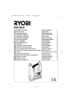
SceneStyle2
User Guide
Mode Lighting (UK) Limited.
The Maltings, 63 High Street,
Ware, Hertfordshire, SG12 9AD,
UNITED KINGDOM.
Telephone: +44 (0) 1920 462121
Facsimile: +44 (0) 1920 466881
e-mail: [email protected]
website: www.scenestyle.co.uk
DS149 V1
Troubleshooting
Unit does nothing
There is an overload, short circuit or open circuit on
that circuit. If the circuit has a load connected, check
the circuit loading and check that there is not a
blown lamp on that circuit. The LED stop flashing
when another scene is selected.
The circuit was overloaded for too long and the
A bulb blew on one circuit. I
auto-shutdown feature has been activated. Select a
have replaced the bulb, but now scene, SceneStyle2 will then attempt to re-start that
that circuit no longer works.
circuit. If a problem persists, check the loading and
check for short circuits or open circuits on that circuit.
Configurable input only works
when the lights are on?
Check that the live-in and live-out connections for
circuit 1 are the correct way round.
The lights flash/flicker at high
levels only?
You have not met the minimum load requirements
for the circuits, or a lamp has blown which has
reduced the load.
Use higher-wattage lamp (you can dim them to
reduce the brightness if required) or replace any
blown lamps.
Remember to isolate the SceneStyle4 before changing
any lamps.
The front fascia plate is warm
This is normal, especially when the unit is heavily
loaded (i.e. 500W or close to 500W of lamps are
connected).
To Reset To Factory Default Level Settings
Light Levels
The default scene settings may be restored at any time by:
simultaneously holding down buttons 1, 2, 3 and 4 together until all of the button LEDs
flash blue (after approx 5 seconds) then releasing all the buttons.
LED Colours
The LED colours and remote input settings are not reset when the factory-default scene
levels are reset. To reset the LED colours, see the previous section on page 11 “Setting
Button LED colours”.
Remote Switches
To reset the function of the remote inputs see the section on advanced set-up on page 12
Please visit our dedicated website for further information regarding
the SceneStyle® range at www.scenestyle.co.uk
For Electronic Transformers see: www.modelighting.com
Page 16
www.scenestyle.co.uk
www.scenestyle.co.uk
Button 1 or 2 is flashing
red/orange
Solution
Check that there is a working load wired in series with
circuit 1.
Check that the lamp on circuit one has not blown
Check that the mains supply is on to the
SceneStyle2 b checking the MCB or in your consumer unit.
Check that the load on circuit 1 is no more than
500W total.
‘The Stylish way to Control your Lighting’
Symptom
Contents
................................................................ Page 1
Introduction
............................................................. Page 2
For the installer
Wiring
.......................................................................
Connecting Two-Way Switches or External Switch Inputs
Page 4
.. Page 5
For every day use
Operation
.................................................................. Page 7
How To Select a Pre-Programmed Scene
......................... Page 7
How To Raise/Lower levels of channels currently illuminated Page 7
How To Raise/Lower the level of a single circuit
.............. Page 7
Programming
Scene Programming
.................................................... Page 8
Setting Button LED Colours
.......................................... Page 11
Blown Bulbs, Short Circuits and Automatic Shut-Down
How To Reset To Factory Default Settings
....... Page 11
........................ Page 16
Advanced Setup
Infrared Remote Control
.............................................. Page 10
Entering Advanced-Setup Mode
Remote Input Options Menu
Group 1 – Two way switching
.................................... Page 12
........................................ Page 13
.......................................................
Group 2 – Scene selection between pre-determined scenes
..............
Group 3 – Scene selection between pre-determined scene and previously
selected scene..................................................................
Group 4 – Scene selection of an individual scene ...................................
Group 5 - Impulse Operation .............................................................
What Is Impulse Operation?
Troubleshooting
......................................... Page 14
..........................................................
[email protected]
Page 16
Page 1
Holiday Mode
SceneStyle2 is a scene-setting, self-contained, dimmer for one or two circuits (also known
as channels or zones) in four scenes, or mood settings. The two circuits can be set to any
combination of levels in each of the four scenes. There are also On ( ) and Off ( )
scenes, which may contain any levels required.
SceneStyle2 can help deter would be burglars by simulating occupancy of your house
by switching lights on and off automatically.
Important Safety Notes
!
!
WARNING: Isolate (turn off) the mains power at the main consumer unit (fuse box)
before commencing installation or performing any maintenance, including changing
blown lamps.
SceneStyle2 is designed to control incandescent (filament) lamps at Mains Voltage or
Low Voltage when fed from a suitable Electronic Transformer. To avoid hazard or possible damage do not use with inductive, fluorescent, wire-wound Transformer or
motor loads.
!
SceneStyle2 must be installed by a qualified electrician or other competent person.
Installation should be in accordance with the National Wiring Regulations or other
applicable Regulations. Compliance with the EC EMC or Low Voltage Directives may
be invalidated, if not used or installed to the published specification.
!
SceneStyle2 is for installation to 230V and 240V single phase mains supplies only.
The cable connected to the Live Input terminal must be capable of supplying the total
current for both circuits (2A maximum).
!
SceneStyle2 must be protected by an external circuit breaker or fuse rated at 6A maximum.
!
SceneStyle2 is a Class 1 product. This unit must be Earthed.
!
SceneStyle2 must be installed in a suitable UK single gang backbox, compliant to
BS4662 or BS5733. We recommend that a 47mm depth backbox is used.
!
SceneStyle2 complies with EN60669-1/EN60669-2-1, EN55105 and EN61547.
!
For indoor use only, at temperatures between 00C and +250C.
!
Do not operate without the front fascia plate correctly fitted.
Page 2
www.scenestyle.co.uk
Button 1
+ 1 hours
Button 2
+ 2 hours
Button 3
+ 3 hours
Button 4
+ 4 hours
✓
✓
✓
✓
✓
✓
✓
✓
✓
✓
No Delay
10 hour
9 hour
8 hour
7 hour
6 hour
5 hour
www.scenestyle.co.uk
All of the circuits which are currently illuminated, or any individual channel on its own,
may be raised or lowered(made brighter or dimmer) at any time without affecting the
programmed scenes.
mode beings. This is done by using a combination of buttons 1, 2, 3 and 4 to indicate
the required time. The delay time is calculated by adding the “values” represented by
buttons 1, 2, 3 and 4 together, as shown in the table below. Press each of the buttons
to toggle them on (green) or off (not-illuminated) to add or exclude their “value”
from the time. For example to delay the start of holiday mode by 5 hours buttons 1
and 4 should be illuminated.
4 hour
Scene 4
☞ Release the buttons
☞ Enter the delay that you require before automatic holiday
3 hour
Scene 3
) and ( ) buttons down together for 5 seconds
until the LEDs on those buttons illuminate green
2 hour
Scene 2
☞ Hold the (
1 hour
Scene 1
To Enable Holiday Mode:
Time until
automatic
holiday
mode
begins
A scene is a pre-programmed set of different brightness levels for a combination of
circuits, that may be recalled at any time by pressing one of the scene-selection buttons.
Scenes are used to create different lighting moods for the area being illuminated.
‘The Stylish way to Control your Lighting’
Introduction
✓
✓
✓
✓
✓
✓
✓
✓
✓
✓
✓
indicates that the button is toggled to the “On” state.
To activate Holiday Mode
☞ Hold down the “ ” and “
☞ Release the buttons.
” buttons for 5 seconds until all LEDs illuminate green.
All LEDs will flash green and the LED showing the current scene will be illuminated red. As
the SceneStyle2 simulates occupance the red LED will change from scene to scene
automatically. The sequence of scenes is as in the table below.
Step Offset from Start Time
1
2
3
4
5
6
7
8
Start
Start
Start
Start
Start
Start
Start
Start
Time
Time
Time
Time
Time
Time
Time
Time
+
+
+
+
+
+
+
30 minutes
1 hour, 30 minutes
3 hours, 30 minutes
6 hours, 30 minutes
12 hours, 30 minutes
13 hours
15 hours
Example: actual time (if Scene
Holiday Mode is delayed automatically
to begin at 6:00pm)
recalled
6:00pm
On
6:30pm
1
7:30pm
2
9:30pm
3
12:00pm
Off
6:30pm
3
7:00am
On
9:00am
Off
☞ To exit holiday mode press any button.
[email protected]
Page 15
Maximum and Minimum Loads
After the second button has been pressed, if a valid selection
is made, you will be returned to step 3 (Page 12). If an invalid
selection is made (i.e. a code that does not exist or an incompatible
switch type) all LEDs will flash red until you press another button,
at which point you will be returned to step 2 (Page 12). Any
invalid settings will not be stored and will be substituted by the
last valid setting.
Note
Note: Some combinations of function and switch type are not allowed eg. Impulse
operation with a volt free contact – The table shows the input types that are allowed
for each option.
What is Impulse Operation?
Impulse operation uses one push button input to select between on, off and raising or
lowering of lighting levels. Alternate short pushes of the button toggle between on and
off. Holding the button down will raise or lower the level of the circuit(s). When the circuit
is switched on it will return to the last “on” level to which it was set.
Description of Switch Types
Momentary action (push button) / Retractive switch - With this type of switch the
remote input will activate whenever the push button / retractive switch is pressed but
not when it is released
Rocker switch (alternate action) - With ‘alternate action’, a rocker switch on the
remote input will activate whenever the rocker is switched to a different position (as it
would with a standard domestic two way switching arrangement)
Rocker switch (fixed action) - With ‘fixed action’ option, a rocker switch on the
remote input will always perform the same action when the switch is opened and a
different action each time the switch is closed.
For example: If a ‘last man out’ rocker switch is connected to two SceneStyles, both set to switch
between the ON ( ) and OFF ( ) scene from a fixed action rocker, the OFF ( ) scene will always
be recalled on both SceneStyles when the switch is opened and the ON ( ) scene will always be
recalled when the switch is closed. However, with an alternate action rocker: if one of the
SceneStyles is in the ON ( ) scene and the other is in the OFF ( ) scene and the rocker switch
is activated both SceneStyles will switch to the opposite scene.
Volt free contact (trigger on contact closure) - With this switch type the remote
input will activate whenever the RTN terminal on the SceneStyle2 becomes live.
Volt free contact (trigger on contact opening) - With this switch type the remote
input will activate whenever live is removed from the RTN terminal of the SceneStyle2.
Page 14
www.scenestyle.co.uk
www.scenestyle.co.uk
To leave advanced setup mode press OFF ( ) twice.
‘The Stylish way to Control your Lighting’
...continued from page 12
The LED’s are extinguished after the first press and the first digit
entered will be illuminated purple.
You do not have to use both circuits, however Circuit 1 must always be connected.
Circuit 1 has a maximum load of 500W and a minimum load of 50W. The total load
connected to the SceneStyle2 must not exceed 500W.
Circuit Maximum Load
Minimum Load
(Mains Lighting)
Minimum Load
(LV Electronic Transformers)
1
500W
50W
100W
2
250W
50W, if used
50W, if used
TIP
If the load connected to Circuit 1 drops below the minimum level shown in the
table above then both circuits will be affected. For example, if the lamp(s) connected to Circuit 1 blows and the resulting load is less than 50W (or 100W if
using electronic transformers) then circuit 2 may no longer function correctly.
Therefore, it is recommended that you make Circuit 1 the circuit to which you
connect the largest number of lamps.
Note
The minimum load figures quoted are for Mode Lighting (UK) Ltd electronic
transformers. SceneStyle2 will operate with other electronic transformers, however,
if they have a high input capacitance (a common problem with low quality goods)
then the minimum load may increase.
!
The SceneStyle2 dimmer is suitable for 12v halogen lamps using only electronic
transformers and not wire wound or toroidal. Suitable electronic low voltage lighting
transformers are manufactured by Mode Lighting (UK) Ltd. Please contact your
SceneStyle2 stockist regarding the correct product for your installation.
You may connect 240V GLS and GU10 lamps to the SceneStyle2 dimmer.
!
SceneStyle2 circuits will shutdown if short-circuited, open circuited or overloaded.
This is indicated by button 1 or 2 flashing red/orange.
!
The front fascia plate will become warm during operation. This is normal.
!
SceneStyle2 does not require a Neutral and may be used to replace normal light switches
or rotary dimmers.
[email protected]
Page 3
Remote Input Options Menu
Wiring
Each of the circuits of the SceneStyle2 dimmer replaces a normal light switch or rotary
dimmer. Circuit 1 must always be used and has a maximum load of 500W and a minimum
load of 50W (100W LV Electronic Transformers). You do not have to both circuits, however
you will still have four available scenes together with On ( ) and Off ( ) available.
NB: The cable connected to the Live-In terminal must be capable of supplying the total
current for both circuits (2A maximum) and must be protected by an external fuse or
miniature circuit breaker (MCB) rated at 6A maximum.
The terminal marked
has no internal connection. You may use it as a terminal to
“park” additional live feeds from lighting circuits other than Circuit 1.
Live In
To Neutral
“Spare” live from
ceiling rose
To Neutral
Note
If the loading of the SceneStyle2 is close to maximum (500W) then the SceneStyle2
and the fascia plate will get warm (this is normal). To keep the temperature rise to
a minimum we advise that if the SceneStyle2 is installed in a wall with some form
of insulation (e.g. fibreglass), that you remove some of that insulation from around
the back-box to allow air movement.
Page 4
www.scenestyle.co.uk
Rocker switch
(fixed action)
Volt free
contact
5
6
7
8
Rocker switch
(alternate action)
1
2
3
4
Push button
/ Retractive
}
}
‘The Stylish way to Control your Lighting’
Live Output to Switch 1
Switched return from
External Switch 1
Switched return from
External Switch 2
Live Output to Switch 2
Live Out Circuit 2
www.scenestyle.co.uk
Live In
Live Out Circuit 1
Input types allowed
1 Input switches its respective circuit / Default setting
✓
✓
✓
✓
2 Input switches both circuits
✓
✓
✓
✓
Group 1 – Two way switching
Group 2 – Scene selection between pre-determined scenes 1
1 Input alternately switches between ‘
’ Scene and ‘
✓
✓
✓
✓
2 Input alternately switches between ‘
’ Scene and Scene 1
✓
✓
✓
✓
3 Input alternately switches between ‘
’ Scene and Scene 2
✓
✓
✓
✓
4 Input alternately switches between ‘
’ Scene and Scene 3
✓
✓
✓
✓
5 Input alternately switches between ‘
’ Scene and Scene 4
✓
✓
✓
✓
6 Input alternately switches between ‘
’ Scene and Scene 3
✓
✓
✓
✓
7 Input alternately switches between ‘
’ Scene and Scene 4
✓
✓
✓
✓
✓
✓
✓
✓
‘ scene
8 Input alternately switches between Scene 1 and Scene 4
Group 3 – Scene selection between pre-determined scene and previously selected scene
1 Input alternatively switches between ‘
’ Scene and previous Scene
✓
✓
✓
2 Input alternatively switches between ‘
’ Scene and previous Scene
✓
✓
✓
3 Input alternatively switches Scene 1 and previously selected Scene
✓
✓
✓
4 Input alternatively switches Scene 2 and previously selected Scene
✓
✓
✓
5 Input alternatively switches Scene 3 and previously selected Scene
✓
✓
✓
6 Input alternatively switches Scene 4 and previously selected Scene
✓
✓
✓
✓
✓
✓
✓
Group 4 – Scene selection of an individual scene
1 Input selects ‘
’ Scene
✓
✓
✓
✓
3 Input selects Scene 1
✓
✓
✓
✓
4 Input selects Scene 2
✓
✓
✓
✓
5 Input selects Scene 3
✓
✓
✓
✓
6 Input selects Scene 4
✓
✓
✓
✓
✓
✓
✓
2 Input selects ‘
’ Scene
Group 5 – Impulse Operation
1 Impulse operation on respective circuit only
✓
2 Impulse operation on both circuits
✓
Group 6 – Special Options
1 Last man out, any Scene to ‘
’, ‘
’ to ‘
[email protected]
’
✓
Page 13
Connecting Two-Way Switches or External Switch Inputs
Advanced Mode allows you to configure special options for the remote inputs (mains
rated switches) by following these steps:
The SceneStyle2 has two pairs of terminals to enable up to two external mains rated
switches to be connected. These switches may be configured to perform one of a number
of different functions using the advanced set-up menu (see Pages 12-14). By default,
they are configured to switch their respective circuit On or Off.
Step 1: Enter advanced setup mode
Hold down ∆ and
∆
☞
buttons together and whilst they are held press sequence 2-1-2-1
Step 2: Setup configuration of remote inputs
Buttons 1, 2 and 3 illuminate green.
☞ Press Button 1 to select Remote Input Options Menu
Step 3: Choose which configurable input to set
up (1 or 2)
Buttons 1 and 2 will be illuminated in red.
☞ Press the button corresponding to the remote input that
you want to set up (i.e. button 1 selects input number 1)
Once selected, the chosen button will flash red whilst you
carry out steps 4 and 5.
☞ If you wish to return to step 2 press “ “.
☞ To return all remote inputs to default settings hold button 1-4 simultaneously untill
all LED’s flash red (approximately 5 seconds), then release all buttons.
Step 4: Choose thetype of switch that is connected to the remote input
Buttons 1 - 5 are illuminated blue to indicate available options.
Button
Number
Switch Type
1
Momentary action / retractive (push button)
2
Rocker (alternate action) - default setting
3
Rocker (fixed action)
4
Volt free contact (trigger on contact closure)
5
Volt free contact (trigger on contact opening)
see Page 14 for description of switch types.
☞ Select the required switch type 1, 2, 3, 4 or 5.
☞ If you wish to return to step 2 press “ “.
Step 5: Choose remote input function
Select a two digit operating function by pressing two buttons to choose the group number
and the second to choose the selection within that group from the table on the following page.
☞ Press 1 indicates the group.
☞ Press 2 indicates the selection from within that group.
www.scenestyle.co.uk
(Other buttons are reserved for future enhanced features)
‘The Stylish way to Control your Lighting’
Entering Advanced Setup Mode
The remote inputs are mains-live and therefore all switches (or volt-free relay contacts)
and the cable to them must be mains rated.
Switches used may be push-buttons or retractive switches, rocker switches or volt-free
contacts.
The Live outputs to the switch terminals are internally connected to the Live-In terminal.
Therefore, it is important to ensure that the permanent live feed is connected to the
Live In terminal and not to the Live-Out terminal – see diagram below.
a)
b)
1
2
c
1
2
c
Example of
a) Remote Switch or push button
b) Remote 2-way Switches
continued on p.14...
Page 12
www.scenestyle.co.uk
[email protected]
Page 5
Setting LED Colours
The fascia plate must be fitted prior to switching on the mains power. Normally the
fitting of the fascia would be delayed until after the wall has been painted and other
non-clean building tasks have been completed.
The LEDs that illuminate the buttons on the SceneStyle2 have two states.
1. They may be set to one of seven colours when they are brightly lit, indicating that a
scene or circuit has been selected
2. They may be set to be either off, or illuminated with a dim colour to indicate that a
button is not selected i.e. a backlit colour.
To fit the fascia, align the left-hand side first,
clipping it onto the side of the plate.
Firmly press the top right corner and then the
bottom-right corner of the fascia until it clicks
into place.
Check that all of the buttons are freely protruding
through the holes in the fascia.
Removing the Front Fascia Plate
A fascia plate may be removed by inserting a
4mm flat-head screwdriver under the tab that
protrudes from the bottom right corner of the
plate, and performing a quarter turn twisting
action.
Be ready to restrain the fascia as it detaches
from the false-plate to avoid damage in
dropping it.
TIP / ADVANCED FEATURE
Circuits may be excluded from a scene so that when that scene is recalled the
excluded circuit stays at its current level. For example, in your living room: if the
circuit was connected to a standard lamp you could control it using the SceneStyle
without affecting the levels of the ceiling/wall lights in the room, however the “ ”
scene would still be able to control all lights.
By default all circuits are included in all scenes.
Page 6
www.scenestyle.co.uk
www.scenestyle.co.uk
Ensure that all of the buttons are able to fit
through the holes. You may need to wiggle
them slightly to ensure that they do not get
trapped behind the fascia.
‘The Stylish way to Control your Lighting’
Fitting the Front Fascia Plate
1) Hold down the ∆ and
buttons for 5 seconds.
LEDs show the seven available bright colours.
2) *Press a button to program your
colour choice for a bright colour
to indicate the selected scene.
LEDs show the seven available dim colours and off.
3) Press a button to program your backlight colour.
*Factory Default Colours
During this Step the bottom right hand button resets the LEDs to the factory default
colours, which are:
On scene:
Green
Off scene:
Red
For scenes 1 to 4 a bright blue LED indicates the scene is currently selected, whilst
other LEDs are lit in dim-blue.
Blown Bulbs, Short Circuits and Shut-Down
The SceneStyle2 contains advanced fault-detection and automatic shut-down circuitry.
If a circuit is overloaded (i.e. if too many bulbs are connected to one circuit), short-circuited or open-circuited, then it will automatically shut down. This does not affect the
other circuit connected to the SceneStyle unit.
If the fault condition was only momentary, for example if a GU10 lamp had blown then
SceneStyle2 will detect this state, and will automatically try to restart the circuit.
If the fault condition prevents the circuit from automatically restarting the LED for the
button corresponding to that circuit will flash alternately red and orange until another
scene is selected. SceneStyle2 will attempt ot restart the shutdown circuit each time a
scen is selected using either the plate scene buttons or the infrared handset.
The fault detection indication can be recalled to display any faults that have not been
rectified. To do this, hold down buttons 1 and 4 until all LEDs flash red/orange. When
both buttons are released, any outstanding faults will be indicated by the LED
corresponding to the circuit alternately flashing red/orange.
[email protected]
Page 11
Infrared Remote Control
Operation
) or Off
The raise and lower buttons perform a master raise/lower function on all of the circuits
in a scene. Any circuits that are programmed to be off (i.e. a level of zero) in a particular
∆
scene will not be altered by the ∆ and buttons.
Further IR codes for use with learning remotes, such as the Philips Pronto®, are available
from www.scenestyle.co.uk. These allow facilities such as individual circuit control.
On
Scene 2
Off
Scene 3
Raise
Scene 4
Lower
Page 10
www.scenestyle.co.uk
www.scenestyle.co.uk
Scene 1
‘The Stylish way to Control your Lighting’
The infrared remote control allows selection of the four scenes, and the On (
( ) scenes.
Scene selection
buttons
(when pressed) or
Channel selection
buttons (Buttons
1&2) for
raise/lower
when held.
On scene button
Off scene button
Raise
Lower
By default the SceneStyle2 will power-up to the Off (
) scene.
To select a pre-programmed scene
☞ Press one of the numbered Scene buttons on the left, or press either the On (
or Off (
)
) button on the right.
☞ The scene will be recalled at the fade time that has been programmed and the
button will illuminate brightly to show which scene has been selected.
By default the pre-programmed Scenes are configured as follows:
Scene
1
2
3
4
On (
Off (
)
)
Factory Default
Both circuits at
Both circuits at
Both circuits at
Both circuits at
Both circuits at
Both circuits at
Settings
90%, 2 second fade
70%, 2 second fade
50%, 2 second fade
30%, 2 second fade
100% (Full On), instant action, no fade
0% (Off), 2 second fade
Double-pressing a button will “snap” to the scene i.e. on instant action rather than a
slower fade.
See the section below on Scene Programming for details on how to set your own lighting
levels for each scene.
To raise or lower the level of all circuits that are currently illuminated
☞ Press and hold either the ∆ (raise) or ∆ (lower) button.
To raise or lower the level of a single circuit at any time
☞ Press and hold one either buttons 1 or 2 on the left, to select the circuit
you wish to alter
☞ Within 5 seconds, and∆whilst still holding the numbered button press
and hold either ∆ or
to raise and lower the circuit brightness.
☞ Release both buttons when the desired level has been reached
Scene Programming
The levels of each circuit may be independently set in each scene. A scene does not
have to contain all of the circuits in an illuminated state.
Each scene has a fade time, which is the amount of time it will take to transition from
the current light levels to the levels that have been programmed into the scene.
Available fade times are 0 (instant change), 2, 4, or 8 seconds. By default scenes will
fade over 2 seconds apart from the On ( ) scene which is set to “snap” on by.
[email protected]
Page 7
Scene Programming
Scene Programming
∆
∆
2
∆
∆
Page 8
∆
∆
∆
www.scenestyle.co.uk
∆
[email protected]
Page 9