1
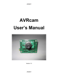
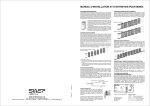
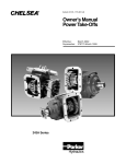
DRO-350 User’s Guide (rev. 4)
SHUMATECH
DRO-350 User’s Guide
1
DRO-350 User’s Guide (rev. 4)
Revision History
Revision Description
1
Original version for software release 1
2
Updated for software release 2
3
Updated for software release 3
4
Updated for software release 4
Table of Contents
Introduction................................................................................................................................. 2
Indicators..................................................................................................................................... 4
Keypad ........................................................................................................................................ 6
Operation..................................................................................................................................... 8
Functions................................................................................................................................... 11
Setup ......................................................................................................................................... 18
Installation................................................................................................................................. 21
Software Upgrade ..................................................................................................................... 21
Auxiliary Devices ..................................................................................................................... 26
Introduction
The DRO-350 is a three-axis digital read-out (DRO) for import Chinese scales and
most quadrature encoders that is designed to be as capable as commercial DROs but be a low
cost alternative for the metal-working hobbyist. One of the more exciting aspects of the DRO350 is that the firmware is easily upgradeable over a serial port. This allows for continued
development of the software and should allow the DRO-350 project to grow over time. Software
is available for both Windows and Linux and you need only a 9 pin serial cable to connect the
DRO-350. More information on the firmware upgrade capability can be found later in this
document. The following list highlights the features designed into the DRO-350.
Features
•
•
•
•
•
•
•
•
Software upgradeable over RS-232 serial port with free Windows software
Fast scale reading with a display update rate of up to 50 times a second per axis
Powers scales for battery-free operation
Triple data sampling for glitch free readings
Three axis display with super high efficiency LEDS for maximum brightness
Display brightness configurable in 20% increments
Max display range of ±99.9995 inches (±999.99 mm)
Incremental and absolute coordinate systems
2
DRO-350 User’s Guide (rev. 4)
•
•
•
•
•
•
•
•
•
•
•
•
•
•
Enter zero values for both coordinate systems entered via keypad
Enter incremental presets via keypad
Separate zero and preset buttons for each axis
Data averaging when the scale is at rest to prevent display jitter
Auxiliary input for either an electronic edge finder or tachometer
Third axis configurable to display tachometer in RPM or SFM
Reversible axis directions
Configurable auto power-off time (none, 15 min, 30 min, 60 min)
Configurable tool offsets entered via keypad
Setup through display and keypad
Setup is retained even if power is removed
Absolute zeroes and inch/metric setting are retained even after a power loss
Configurable CPI for use with quadrature encoders (10-25000 CPI)
Polarity axis setting to alter the location of the origin
Mill-Only Features
•
•
•
Centerline function for any axis
Bolt hole patterns with programmable start and end angles
Cutting edge compensation based on tool offsets
Lathe-Only Features
•
•
Diameter mode (2X) for any axis with a LED indicator displayed in each axis
Compound vectoring into cross-slide and carriage with configurable angle
DRO-350 Front Panel
There are two versions of the DRO-350, the DRO-350M for mills and the DRO-350L for lathes.
The difference in the front panels is that the Y and Z axes on the DRO-350M are replaced with
the Z1 and Z2 axes on the DRO-350L. The front panel is dominated by the three large LED
displays which show the position of each axis as well as other information. Above the displays
are five LED indicators that show current state and status. The right half of the DRO-350
contains the keypad. The keypad is used to set presets, set zeros, change modes, begin functions,
enter values, etc.
The following two figures show the front panel for each version of the DRO-350.
3
DRO-350 User’s Guide (rev. 4)
DRO-350M Front Panel
DRO-350L Front Panel
Note that the software images for the DRO-350M and DRO-350L are also different. The
previous release included a universal image that was the same for both DRO-350 versions. This
release introduces a separate image for each. Differences in operation between these two images
are noted in this document via DRO-350M and DRO-350L labels.
Indicators
INCR Incremental Mode
This indicator is on when the DRO-350 is in incremental mode. All three axes will
display their positions relative to their incremental zeros. When the indicator is off, the
DRO-350 is in absolute mode and each axis will display its position relative to its
4
DRO-350 User’s Guide (rev. 4)
absolute zero.
Incremental zeroes are NOT retained if the power is removed.
The
MM
key toggles between incremental and absolute modes.
Metric Mode
This indicator shows when the DRO-350 is in metric mode. When in metric mode, all
positions either displayed by the DRO-350 or entered via the keypad are in millimeters.
When the indicator is off, the DRO-350 is in imperial mode and all positions are in
inches.
Imperial/metric mode is retained even if the power is removed.
The
key toggles between metric and imperial modes.
ZERO Absolute Zero Set
The absolute zero set indicator is on when the DRO-350 in the middle of setting an
absolute zero. The
key or the axis
set key must be pressed to complete the
absolute zero set. Alternatively, the electronic edge finder can be used to trigger the
absolute zero set at the position where an edge is contacted.
Absolute zeroes are retained even if the power is removed.
SET
Set Value
The set value indicator is a prompt that the DRO-350 expects the user to enter a number
on the numeric keypad. A zero is displayed on the axis that the set is applied to.
FUNC Function
5
DRO-350 User’s Guide (rev. 4)
The function indicator turns on when the
key is pressed to indicate that a number
on the numeric keypad should be pressed to access a special function. The indicator is
kept on for the time the special function is active. When it turns off, the DRO-350 is
back in its normal mode.
Keypad
X Preset
This key begins a preset operation on the X axis. See the operation section for
more detail on how to set a preset.
Y/Z1 Preset
This key begins a preset operation on the Y axis for a DRO-350M or the Z1 axis
for a DRO-350L. See the operation section for more detail on how to set a
preset.
Z/Z2 Preset
This key begins a preset operation on the Z axis for a DRO-350M or the Z2 axis
for a DRO-350L. See the operation section for more detail on how to set a
preset.
Zero Axis
This key is used to set either an incremental or absolute zero on an axis. For
detailed information on setting axis zeros, see the operation section.
Absolute zeros are retained even if the power is removed but incremental zeros
are not.
6
DRO-350 User’s Guide (rev. 4)
Numeric Keypad
Numbers are entered into the DRO-350 via the numeric keypad. It is used
during preset and zero operations to enter offsets and is also used to enter
information for function operations. The set indicator is lit when the DRO-350
expects the user to enter a number on the numeric keypad.
key is used to finish number entry.
The
The
key is used to delete the right-most digit or decimal point. If the
number displayed is a single zero, it will end number entry without entering the
number.
Decimal Point
This key enters a decimal point at the current position when entering a number
on the numeric keypad.
The
position.
key can be used to delete the decimal point if it is at the right-most
Sign
The sign key toggles between a positive or negative value while entering a
number on the numeric keypad. It can be pressed at any time during number
entry.
Clear
The clear key serves a variety of uses:
•
On initial power on, it clears the "dro350 r<version>" boot screen.
•
During number entry, it deletes the right-most digit or decimal point. If
the number is a single zero, it will end number entry without entering a
number.
7
DRO-350 User’s Guide (rev. 4)
•
During setup, it serves as a back key while paging through the setup
screens.
•
During functions, it serves as a back key while moving through function
steps.
Enter
The enter key serves a variety of uses:
•
During number entry, it is used to finish entering the number.
•
During setup, it serves as the forward key while paging through the
setup screens.
•
During functions, it serves as the forward key while moving through
function steps.
Absolute/Incremental Toggle
This key toggles between absolute and incremental positions for all axes.
Imperial/Metric Toggle
This key toggles between imperial (inches) and metric (millimeters) modes for
all axes.
Imperial/metric mode is retained even if the power is removed.
Function Key
The function key is pressed before one of the numbers on the numeric keypad to
begin a special function.
Operation
8
DRO-350 User’s Guide (rev. 4)
Power On
When the DRO-350 is first powered on, it will display a "dro350 r<version>" message on the
display where <version> is the number of the software version. The DRO-350M version will
also display a "mill" message while the DRO-350L will display a "lathe" message. The message
key. This is to prevent accidental use of different
can only be removed with the
incremental zeros since they are lost after power is removed.
The DRO-350 has an automatic power off feature that can be set to activate after a configurable
period of inactivity. The inactivity time is programmed during setup. Alternatively, the
keys can be pressed to immediately power off. It is recommended to leave the DRO-350
plugged in and use the automatic power off so that the absolute and incremental zeros are saved.
A negligible amount of current is consumed when the DRO-350 is powered off.
Fast Mode
The DRO-350 programs Chinese scales into fast mode where they will update their readings at
up to 50 times a second instead of the usual 3 to 5 times a second. Fifteen seconds after power
on, the DRO-350 will perform the fast mode programming. You will know when this occurs
because the display will briefly flash. If any scales are already in fast mode, the DRO-350 will
detect this and skip fast mode programming for those scales. The fifteen second delay is
necessary because some scales do not respond to fast mode programming for several seconds
after they are powered on.
Scale Readings
The DRO-350 uses counts for all internal calculations and processing. The Chinese scales have
a resolution of 20,480 counts per inch (CPI). Quadrature encoders can be configured for any CPI
between 1 and 25,000. The counts are converted to inches or millimeters just prior to display.
Also, if values are entered via the keypad, they are converted and stored in counts. This is done
to provide maximum accuracy and minimize rounding errors during complex calculations such
as with bolt-hole circles. No rounding is done on the scale readings displayed on the DRO-350
to minimize errors. The displayed readings are truncated to the display resolution.
Absolute Zero
Start an absolute zero set on an axis by pressing the
key for that axis when the DRO-350
is in absolute mode. The zero set indicator will turn on indicating that an absolute zero set is in
progress. After an absolute zero set is started, there are three ways to set the absolute zero, at the
9
DRO-350 User’s Guide (rev. 4)
current position, by an offset from the previous absolute zero, or at the position of an electronic
edge finder.
•
Set an absolute zero at the current position by pressing either the
key at the desired position.
•
Set an absolute zero by an offset from the previous absolute zero by pressing the first
number of the offset on the numeric keypad. The DRO-350 will switch to set mode and
key or the
you can continue entering the offset via the numeric keypad. Use the
complete the offset and the
•
key to
key to make corrections or cancel the absolute zero set.
Set an absolute zero with an electronic edge finder by contacting the work piece with the
electronic edge finder. An absolute zero is set at the current position on the instant of
contact. Before using the electronic edge finder, make sure it is properly connected to the
DRO-350 and that the auxiliary setting in the setup is set to "yes". More details on the
electronic edge finder operation are in the auxiliary devices section.
Incremental Zero
Set an incremental zero at the current position by pressing the
key when the DRO-350 is
in incremental mode. The incremental zero is set immediately without any additional key
presses.
Absolute Preset
An absolute preset is an incremental zero set at an absolute position. With the DRO-350 in
absolute mode, press the preset key for the desired axis. The DRO-350 will switch to set mode
and you can enter an absolute position via the numeric keypad. Use the
the position and the
key to complete
key to make corrections or cancel the absolute preset.
Incremental Preset
An incremental preset is an incremental zero set at an offset from the current position. With the
DRO-350 in incremental mode, press the preset key for the desired axis. The DRO-350 will
10
DRO-350 User’s Guide (rev. 4)
switch to set mode and you can enter an offset via the numeric keypad. Use the
complete the offset and the
key to
key to make corrections or cancel the incremental preset.
Functions
Functions are started by first pressing and releasing the
key. The FUNC indicator will
turn on indicating that a number key
through
should be pressed for the desired
function. The FUNC indicator will remain on for the course of the function. Differences in the
functions between the mill and lathe images are noted below via DRO-350M and DRO-350L
labels, respectively.
Setup
This function enters the DRO-350 setup. Detailed information on setup is in the setup
section.
Centerline
DRO350M
Centerlines are meant to quickly find center points in lines and circles. The centerline
function sets a zero at the half way point between the current zero and current position
for an axis. If the scale is in incremental mode, the zero will be an incremental zero.
Vice versa, if in absolute mode, the zero will be an absolute zero.
Set a centerline zero by first moving to the desired position. Switch to incremental or
absolute mode with the
key for the desired zero type. Press the
keys and the DRO-350 will display a prompt to press the preset key for the axis the
zero is desired on.
Diameter Mode
Diameter mode allows work in diameter dimensions instead of radius dimensions.
When an axis is in diameter mode, the axis reading is doubled and any zero or preset
11
DRO-350 User’s Guide (rev. 4)
positions entered via the keypad are taken as diameter dimensions.
DRO350L
After pressing the
keys, the DRO-350 displays a prompt to hit the preset
key for the axis that diameter mode is desired on. The left-most decimal point in the
display is turned on for that axis to indicate that the axis is currently in diameter mode.
Selecting an axis already in diameter mode will turn it off.
Diameter mode is retained even if the power is removed.
Bolt-Hole Pattern Define
DRO350M
This function defines a new bolt-hole pattern for use with a mill. The bolt-hole pattern
is stored in non-volatile memory on the DRO-350 and is retained even if power is
removed.
Define a bolt-hole pattern by pressing the
keys. The first screen will
prompt you to enter the number of holes from 1 to 99 via the numeric keypad. When
entering numbers while defining the bolt-hole pattern, press the
key to complete
the number or the
to make corrections or exit. After entering the number of
holes, the next prompt will be for the radius of the bolthole circle. Next, the starting
and ending angles of the bolt-hole circle are entered. The angles are entered in degrees
and with respect to the following diagram when looking at the bolt-hole circle from the
top:
The valid angle ranges are from 0.0 to 359.9 degrees. If the same angle is entered for
both the starting and ending angles, a full circle bolt-hole pattern is created. After
entering the end angle, the bolt-hole pattern is stored in the DRO-350.
12
DRO-350 User’s Guide (rev. 4)
Compound Angle Define
DRO350L
This function sets the angle of the compound for use when vectoring the compound
(Z2 axis) movement into the cross-slide (X axis) and carriage (Z1 axis). The
compound angle is stored in non-volatile memory on the DRO-350 and is retained
even if power is removed. Positive angles indicate that the compound is positioned
clockwise from the center position and negative angles indicate that the compound is
positioned counter-clockwise.
Enter the angle from positive to negative 99.9 degrees with the numeric keypad and
press the
key to accept the angle. Press the
without setting the angle.
to make corrections or exit
Bolt-Hole Pattern Use
DRO350M
This function uses the defined bolt-hole pattern to set X and Y axis incremental zeros
at each bolt-hole position in the pattern. The center of the bolt-hole pattern is always
taken as the incremental zero of the X and Y axes when the function is started so
before starting this function, set X and Y incremental zeros at the center of the bolthole pattern. Press the
keys and a "hole 1" prompt is displayed. This
indicates that an incremental zero is about to be set for the first bolt-hole. Press the
key and the DRO-350 switches to displaying the axis positions so that you can
move the X and Y axes to zero for the first bolt-hole. Press the
key again and
continue through the bolt-hole pattern. After the incremental zero is set for the last
13
DRO-350 User’s Guide (rev. 4)
bolt-hole, press
to exit out of the bolt-hole pattern use function. The
incremental zeros for the X and Y axis are restored to the values that were defined for
the center of the bolt-hole pattern. If you make a mistake, you can go backward
through the screens at any time with the
key.
Compound Vectoring
DRO350L
This function toggles compound vectoring on and off. Compound vectoring takes the
movement of the compound (Z2 axis) and vectors (or sums) it into the cross-slide (X
axis) and carriage (Z1 axis) according to the current angle set for the compound. For
example, if the compound angle is set to 30 degrees and the compound is moved
1.000, then vectoring would add 1.000 * sin(30) = 0.5 to the cross-slide and 1.000 *
cos(30) = 0.866 to the carriage.
Compound vectoring mode is retained even if the power is removed.
Tool Offset Define
DRO350M
This function defines one of 9 tool offsets for cutting edge compensation. The tool
offsets are stored in non-volatile memory on the DRO-350 and are retained even if
power is removed. The tool offsets are defined in terms of the tool diameter and the Z
axis offset.
Define a tool offset by pressing the
keys. The first screen will prompt
you to enter the tool offset number 1-9 with the numeric keypad. After pressing the
number, you will be prompted to enter the tool diameter. When entering the offsets,
key to complete the offset or the
to make corrections or exit.
press the
Next, you will be prompted to enter the Z offset. After entering the Z offset, the tool
offset is stored in the DRO-350.
Tool Offset Define
This function defines one of 9 tool offsets for lathe operations. The tool offsets are
stored in non-volatile memory on the DRO-350 and are retained even if power is
14
DRO-350 User’s Guide (rev. 4)
DRO350L
removed. The tool offsets are defined as offsets of the X and Z1 axes. The following
figure shows a visual representation.
Define a tool offset by pressing the
keys. The first screen will prompt
you to enter the tool offset number 1-9 with the numeric keypad. After pressing the
number, you will be prompted to enter the X offset. When entering the offsets, press
the
key to complete the offset or the
to make corrections or exit. Next,
you will be prompted to enter the Z1 offset. After entering the Z1 offset, the tool
offset is stored in the DRO-350.
Tool Offset Use
This function selects one of the defined tool offsets. Use a tool offset by pressing the
DRO350M
keys. The DRO-350 prompts you to select a tool offset number 0-9 with
the numeric keypad. Tool offsets 1-9 are defined by the user whereas tool offset 0 is
implicitly a tool with no offsets and is effectively used to turn off tool offsets.
After selecting the tool offset, use the numeric keypad to select the cutting edge to
compensate for. The edge positions are selected according to the following keypad
pattern.
15
DRO-350 User’s Guide (rev. 4)
When an axis position is compensated due to an edge position selection, the left-most
decimal point in the display for that axis is turned on.
The tool offset in use is retained even if the power is removed though the cutting edge
is not.
Tool Offset Use
This function selects one of the defined tool offsets. Use a tool offset by pressing the
DRO350L
keys. The DRO-350 prompts you to select a tool offset number 0-9 with
the numeric keypad. Tool offsets 1-9 are defined by the user whereas tool offset 0 is
implicitly a tool with no offsets and is effectively used to turn off tool offsets.
The tool offset in use is retained even if the power is removed.
Tachometer
The tachometer function is only available if the auxiliary setting in the setup is set to
yes. Selecting this function will toggle between the Z/Z2 axis position and the
tachometer reading in RPM. Details on the tachometer operation are in the auxiliary
devices section.
Tachomter mode is retained even if the power is removed.
Surface Feet Per Minute
DRO350M
The surface feet per minute (SFM) function is only available if the auxiliary setting in
the setup is set to "on". This function takes the RPM reading from the tachometer and
the currently selected tool diameter and calculates the SFM with the equation SFM =
(RPM * 2 * PI * radius) / 12. The result is displayed on the Z axis.
Selecting this function will toggle between the Z axis position and the SFM reading.
Details on the tachometer operation are in the auxiliary devices section.
SFM mode is retained even if the power is removed.
Surface Feet Per Minute
DRO-
The surface feet per minute (SFM) function is only available if the auxiliary setting in
the setup is set to "on". This function takes the RPM reading from the tachometer and
the absolute position of the X axis as the radius and calculates the SFM with the
16
DRO-350 User’s Guide (rev. 4)
350L
equation SFM = (RPM * 2 * PI * radius) / 12. The result is displayed on the Z2 axis.
Selecting this function will toggle between the Z2 axis position and the SFM reading.
Details on the tachometer operation are in the auxiliary devices section.
SFM mode is retained even if the power is removed.
Power Off
This function is used to immediately power off the DRO-350. When powered off, all
display elements are turned off and only a small amount of current is used. The scales
are kept powered on so that the zeros are not lost.
Fast Mode Toggle
Pressing the
key followed by one of the axis preset buttons will program the fast
mode sequence on the Chinese scale connected to that axis. This function can be used
to put a newly connected scale into fast mode without powering the DRO-350 off and
back on.
Counts Display
This function is used to display the raw counts in hexadecimal format for each axis
instead of the corresponding reading in inches or millimeters. This function is used for
troubleshooting and helping to determine the threshold for the averaging filter.
Entering this function keypress again will change the display back to a reading in
inches or millimeters.
17
DRO-350 User’s Guide (rev. 4)
Setup
Setup is entered by pressing the
keys. The setup screens are show in order below.
key to move forward and the
key to move
Setup is navigated by pressing the
backward. The setup is saved to non-volatile memory when you move forward from the last
screen. You can make changes to setup without saving them to non-volatile memory by going
backward through the screens until you exit setup without moving forward on the last screen.
The possible options for each setting are cycled through by pressing the preset key for the axis
you want to change. If a setting is not axis-specific, then press any preset key to cycle through
the options.
Direction
This setting controls the direction of travel of the scale for each axis.
Pressing the preset button for an axis will toggle between "fo" (forward)
and "re" (reverse) for that axis. Adjust this as necessary to get the
correct direction of travel depending on how your scales are installed.
Polarity
This setting controls the polarity of each axis for use in changing the
origin position. This setting affects all of the functions that operate on
absolute directions such as tool offsets, bolt hole circles, etc. By
default, this setting is "po" for positive which corresponds to
default origin positions as follows:
DRO-350M:
•
•
•
X - positive towards the right
Y - positive towards the rear
Z - positive up
DRO-350L
•
X - positive towards the front
18
DRO-350 User’s Guide (rev. 4)
•
•
Z1 - positive towards the right
Z2 - positive towards the right
To change the origin to the opposite position, change this setting to "ne"
for negative. For example, if the Y axis is changed to "ne", then it will
be positive towards the front instead of the rear.
Counts Per Inch
The counts per inch (CPI) setting is for quadrature encoder use. The
valid CPI range is from 10 to 25000 and must be a multiple of 10. For
Chinese scales, a CPI setting of 20480 should be used. To set the CPI
for an axis, press the preset button for that axis and enter the setting on
the numeric keypad. Press the
press the
key to confirm the setting or
key to erase digits or to cancel entry.
When using the QCC-100, the value here must be four times the
resolution of the disk or strip used by the quadrature encoder. The
reason for this is that the QCC-100 quadruples the resolution and this
must compensated for here. For example, a 500 CPI strip would be
entered as 2000 CPI here.
Filter Threshold
This setting controls the threshold in counts for the digital averaging
filter for each scale. This filter attempts to keep the axis reading from
bouncing or jittering when the scale is not moved so a steady reading is
displayed. When the scale is moved more than the threshold, the filter
immediately displays unfiltered readings until the scale is stopped
again. After the scale is stopped, the filter will again average readings
together to arrive at a steady reading.
Press the preset key for an axis to enable threshold entry. Use the
numeric keypad to enter the threshold in counts and press the
key. The
key is used to erase digits or to cancel the threshold
19
DRO-350 User’s Guide (rev. 4)
entry altogether.
This threshold setting is a tradeoff between stability and being able to
detect small amounts of travel. Increase this setting if the scale reading
bounces too much and set it lower if you want more sensitivity to small
movements.
Oversample
This setting controls the triple oversampling built into the DRO-350
that helps reduce the effects of noise on the scale signal lines. A small
minority of Chinese scales have a serial stream with an output
frequency that is much faster than most and it may be too fast for the
processor inside the DRO-350 to handle while performing triple
oversampling. By setting this to "n", the DRO-350 can support these
scales with the drawback of reduced noise immunity. Setting this to "y"
turns on triple oversampling and is the recommended and default setting
for most scales.
Intensity
This setting controls the intensity of the indicator and display LEDs.
Pressing any preset key will toggle between the following values:
•
•
•
•
•
5 - 100% intensity
4 - 80% intensity
3 - 60% intensity
2 - 40% intensity
1 - 20% intensity
Auxiliary Device
The auxiliary device in use on the DRO-350 is selected by this setting.
Pressing a preset key will toggle between "tach" for tachometer and
"edge" for electronic edge finder. If no auxiliary device is in use, leave
the setting on its default value of "tach".
Auto-Off
20
DRO-350 User’s Guide (rev. 4)
The inactivity time before automatically powering off is controlled by
this setting. If there is no interaction with the DRO-350 keypad for this
amount of time, then it will automatically power off. Pressing any key
will power the DRO-350 back up. The possible values selected with
the preset key are 60, 30, and 15 minutes.
Installation
Installation of the DRO-350 and the Chinese scales is highly dependent on the machine it is
being installed on. Check the ShumaTech message board to see if you can find specific
recommendations for your machine.
One important installation recommendation has to do with the Chinese scales. These scales have
a metal back that is connected to the positive side of the battery. When mounted on the machine,
the scales are electrically coupled together through the machine. The DRO-350 powers the
scales by providing 1.5V DC over the scale cables so that the batteries are not necessary. If the
batteries are removed, some scales my bounce around more than when the batteries were
installed. This is due to lack of filtering of the power supplied by the DRO-350 at the scale. If
you experience this problem, it can be overcome one of two ways.
The first way is to solder a 100uF capacitor across the battery leads on the scale. This will
provide the necessary filtering of the power supply and the scales will be just as quiet as when
the battery is installed. You won't need to worry about batteries ever again since the DRO-350
will supply all of the power needed by the scale. Look at the modifications page for detailed
instructions on how to install the capacitor on the scale.
If you don't want to solder a capacitor to your scales, the other alternative is just to leave the
batteries in the scales. The DRO-350 will still supply power to the scales so the batteries will
drain much slower than normal. Batteries essentially look like a large capacitor to a circuit so
this will supply the necessary filtering of the power supply as well.
Software Upgrade
The DRO-350 has a built-in programmer for its PIC microcontroller. This allows the software to
be easily upgraded over a serial port. There are two programs recommended for use with the
DRO-350, IC-Prog and PonyProg. Detailed instructions for each program is given below.
Before starting the software, you must connect the DRO-350 to your computer. Do so by
connecting the DRO-350 with a standard DB-9 serial cable to a free serial port. IMPORTANT:
Disconnect the power supply, auxiliary device, and scales from the DRO-350. The serial port
provides all necessary power while programming the DRO-350.
IC-Prog
21
DRO-350 User’s Guide (rev. 4)
Download IC-Prog from the web site and follow the installation instructions. Start the program
and select the Settings -> Hardware from the menu. You will be presented with the following
dialog box:
Select "JDM Programmer" from the drop down list under "Programmer:". Select the serial port
that you connected the DRO-350 to in the "Ports" section. The "Interface" setting will normally
be correctly set so do not change it unless IC-Prog gives you a serial communications error.
Leave the "I/O Delay" and "Communication" settings alone. Click "OK" to save the settings.
Next, do a preliminary check of the serial interface by selecting Settings -> Hardware Check
from the menu. The following dialog box will come up:
Turn on "Enable MCLR" by selecting the check box. The programming LED on back of the
DRO-350 should come on. If it does not, check your serial connection and also make sure that
you unplugged all other cables from the DRO-350. Unselect the check box and clock "OK" to
continue.
The next step is to select the correct PIC microcontroller from the device list. The DRO-350
uses the PIC16F876A microcontroller so select it from the device list. This is shown in the
following window:
22
DRO-350 User’s Guide (rev. 4)
Now you are ready to open the DRO-350 software image. Download the desired software image
from this web site and extract the HEX file. The file name will be in the format dro350r<ver>.hex where <ver> is the software version. Select File -> Open from the menu and
open the HEX file. Once you do this, you should see a window similar to the following:
23
DRO-350 User’s Guide (rev. 4)
The program code window should now show hexadecimal numbers other than just 3FFF and the
configuration on the right should be set as shown above. The oscillator, write enable, fuses, and
checksum are set correctly from the HEX file so do not change them after opening the HEX file.
Note that the checksum will be different in every software version and will not be the same as
what is shown above. You are now ready to start programming the DRO-350. Select Command
-> Program All from the menu. IC-Prog will ask for confirmation for the operation. Select
"Yes" and you will be presented with the following dialog box:
If IC-Prog shows a serial communications error message, first double check that you are using
the correct serial port. If so, then go to Settings -> Hardware and try changing the "Interface"
setting.
After programming completes, the code is verified and you will see the following dialog box:
24
DRO-350 User’s Guide (rev. 4)
IC-Prog will show the following dialog box if the verification is successful.
If the verification fails, don't worry, no permanent damage is done. There are two common
verification failures - data and code. A data verification failure can be safely ignored and just
means that the EEPROM was not fully zeroed. The message displayed will say "Verify failed at
data address XXXXh". Note the word "data" in front of "address".
If the message says "Verify failed at address XXXXh", note that the word "data" is not in front
of "address", then the code verify failed and there is some sort of problem.
Here is a list of common problems to check for:
•
•
•
•
•
Unconnected or incorrectly wired signals between the DB-9 connector and JP1
Using a null modem cable instead of the required straight-through cable
Diode D2 is soldered in the via inside of the white outline instead of the hole on the
outside
One of the diodes D2-D7 has the wrong orientation
The I/O delay setting in IC-Prog (Hardware -> Settings) is either too fast or too slow for
the computer. Try a few slower and faster values.
25
DRO-350 User’s Guide (rev. 4)
•
The computer's serial port is not generating enough voltage swing. The programming
LED not coming on is one sign of this. Try programming on another computer. Newer
computers and laptops are more likely to have this problem.
Auxiliary Devices
Tachometer
The tachometer function of the DRO-350 is used to display the spindle speed of a mill or lathe.
A small probe that optically measures the rotational speed is mounted to the machine. The probe
sends a 5V pulse to the DRO-350 through the auxiliary connector for every rotation of the
spindle. The DRO-350 measures the period between these pulses and converts it to either RPM
or SFM for display on the Z/Z2 axis. The tachometer display is updated once per second.
Electronic Edge Finder
Absolute zeros can be set on the DRO-350 with an electronic edge finder by contacting the work
piece with the edge finder while it is mounted in the spindle. Many commercially available edge
finders can be adapted for use with the DRO-350. A circuit inside the edge finder sends a 5V
pulse to the DRO-350 through the auxiliary connector. To set the absolute zero for an axis with
the electronic edge finder, set the DRO-350 to absolute mode and press the
button once
for that axis. When the edge finder contacts the work piece, the axis is zeroed at the current
position. To compensate for the diameter of the edge finder, use a tool offset with the cutting
edge compensation feature.
26