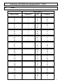
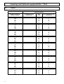
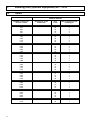
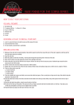
1
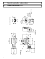
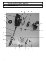
Operating instructions
Dividing attachment
No. 11501
No. 11510
Walter Blombach GmbH
Tool and Machine Factory
D-42899 Remscheid Am Blaffertsberg 13 Phone: 0049 (2191) 597-0 Fax: 0049 (2191) 597-40
D-54673 Neuerburg WABECO Str. 1-10 Phone: 0049 (6564) 9697-0 Fax: 0049 (6564) 9697-25
www.wabeco-remscheid.de
E-Mail: [email protected]
E-Mail: [email protected]
Index
1.
1.
Area of application
2
2.
2.1
2.2
Construction features
Dividing attachment No. 11501
Dividing attachment No. 11510
2
2
3
3.
Technical data
3
4.
4.1
4.2
4.2.1
4.3
General construction and operation
General construction
Illustration
Legend
Operation
4
5
6
7
8
5.
Maintenance and lubrication
8
6.
6.1
6.2
6.3
6.4
6.5
Indexing unit (optional equipment) No. 11514
Indirect division
Example 1
Example 2
Example 3
Tables
9
10
11
11
11
12
Area of application
Dividing attachments vertical/horizontal
for machining on several sides – for work pieces are to be spot faced or counter sunk around the
circumference, which can also be circular, e.g. milling polygons, hole patterns on a circle, splined
shafts, helical grooves and toothed wheels
.
2.
Construction features
2.1
Dividing attachment No. 11501
•
•
•
•
•
•
•
•
•
•
•
2
enclosed construction prevents the ingression of dirt and swarf
hardened and ground adjustable worm
clamping table swivels on a scraped flat bed
quick clamping device
holding jig: vertical and horizontal
3 radial clamping T-slots
width of T-slots 10 mm
construction height 70 mm
trough spindle bore MT2
table diameter 110 mm
weight: 7 kg
2.
Construction features
2.2
Dividing attachment No. 11510
•
•
•
•
•
•
•
•
•
•
•
3.
enclosed construction prevents the ingression of dirt and swarf
hardened and ground adjustable worm
clamping table swivels on a scraped flat bed
quick clamping device
holding jig: vertical and horizontal
4 radial clamping T-slots
width of T-slots 10 mm
construction height 80 mm
trough spindle bore MT2
table diameter 150 mm
weight: 12 kg
Technical data
Accuracy (max. deviations):
• truth of rotation of the work bench
• parallelism of the clamping surface of the clamping table to the base surface
• parallelism of the drilling axis with respect to the vertical clamping surface
• parallelism of the drilling axis with respect to the slots of the vertical
clamping surface
• parallelism between the vertical clamping surface and the axis of connection
taper center - point of tailstock
• dividing precision
• clamping table with scale
• worm drive ratio
• rotations handwheel per 1 turn clamping table
• one turn of the handle turns the table
• the graduation ring is stepped in increments of
0.02 mm
0.02 mm
0.03 mm
0.02 mm
0.02 mm
45”
360°
90:1
90
4°
2 min.
- Technical details are subject to change -
3
General construction and operation
4.1
General construction No. 11501
57.5
20
36.5 41.5
12
7
11
15.5
16
22.5
22
option of affixing by 3 T-nuts
4.
20.5
72
137
58
80
115
11
115
41.5
Ø110
16
36
22
Ø85
4
56
70
Inner taper MT2
135
4
General construction and operation
4.1
General construction No. 11510
option of affixing by 4 T-nuts
4.
20
11
73
7
10
185
8
15.5
25
75
80
15
Ø150
203
63
102
17.5
150
16
51
65
Inner taper MT2
13
163
10
16
(104)
65
10
13
11
Ø100
5
4.
General construction and operation
4.2
Illustration No. 11510
19
18
20
03
01
04
21
02
05
11
16
10
14
15
06
22
07
12
6
09
17
08
13
4.
General construction and operation
4.2.1
Legend
Part-No.
Pieces
Designation
01
02
03
04
05
06
07
08
09
10
11
12
13
14
15
16
17
18
19
20
21
22
1
1
1
1
1
1
1
1
1
1
1
1
1
1
1
2
1
2
2
6
4
4
Case
Rotary table
Worm wheel
Limiting ring
Worm shaft
Retainer ring
Excentric
Holding disk
Graduated collar
Rating nut
Set screw
Indicator ring
Attachment bolt
Fit-in key
Handwheel
Set screw
Hand gripp
Clamping lever
Clamping piece
Fixing bolt worm wheel
Fixing bolt limiting ring
Fixing bolt retainer ring
7
4.
General construction and operation
4.3
Operation
The workpiece to be machined is clamped in place by means of T-slots or hexagonal head cap
screws into the appropriate slots.
For the easiest possible operation and quick setup, release the clamping lever of the excentric
mechanism (11 ) and two clamp levers (18+19). By swiveling the indicator ring (12) by hand to the
left so that the worm (05) on the worm wheel (03) is disengaged. In this way it is possible to move
the rotary table (02) manually.
Subsequently, rotate the indicator ring (12) in the opposite direction in order to engage the worm
(05) and the worm wheel (03) and clamp the clamping lever of the excentric mechanism (11). The
correct position can now be set by rotating the table via handwheel (15).
After adjusting workpiece onto rotary table, set scale ring (09) and indicator ring (12) to zero
degree position. For this you have to release pin screws onto it´s circumference, set rings to zero
degree position and fix screws again.
After the correct division has been set, the rotary table (02) must be fixed in place using the
clamping lever (18+19).
When using the rotary table in a vertical position in connection with the tailstock, make sure that
the guideway is exactly aligned and coincides with the T-slots on the table.
5.
Maintenance and lubrication
When using and transporting the dividing attachment, extreme care must be taken of all machined
surfaces on the table.
In order to maintain the high precision of the dividing attachment over an extended service-life
period, do not expose the rotary table or the clamped workpieces to severe impact or blows.
After operation, remove all chips and residual cooling mediums and oil the table surface to prevent
it from rusting.
Grease the worm before placing into operation (two grease fittings).
8
6.
Indexing unit (Optional equipment) No. 11514
6.1
Indirect division
The dividing attachment can be equipped with an indexing unit (optional).
When working with an indexing device, the following parts on the rotary table must be removed and
then be replaced by the indexing unit: attachment bolt (13) and handwheel (15).
The indexing unit is consisting of the following parts:
Sector arm (1) with pin (2) , three-pieces indexing disk (3), spring steel sheet (4), shear (5) and
three screws M4x16 (6).
Attach the indexing disk (3) using the three screws M4x16 (6) at the indicator ring (12).
After this move on the shear (5) over. It is to be fixed with spring steel plate (4) and index washer
onto surface. Fix sector arm (1) with attachment screw (13) onto spiral lever (05).
After selecting the hole-circle diameter and the corresponding angle of the shear (5) from the table,
remove the pin (2) and rotate the sector arm (1) for divisions.
The graduation of 2 to 100 can be carried out quickly and easily.
Engagement equation: Since the ratio of the worm drive is 1:90, the supporting table is rotated by
1/90 when the crank handle is rotated 360°. The ratio between crank handle rotation "N" and the
number of divisions "T" to be equated is shown in the following equation: N = 90/T.
3
5
6
2
4
1
9
6.
Indexing unit (Optional equipment) No. 11514
6.1
Indirect division
The rotary table is driven by a worm and worm wheel. Make sure that the clamping lever (18+19)
on the table is not tightened.
T
Division number/number of divisions
<
Angular division in degrees (°)
i
= 90° transmission ratio in indexing unit
= Number of crank revolutions for a complete revolution of the workpiece
nk
Number of crank revolutions for a dividing step (can be a fraction, a mixed number or a whole
number)
Number of holes on the hole circle of the hole disk
10
A
15, 16, 17, 18, 19,
20
B
21, 23, 27, 29, 31,
33
C
37, 39, 41, 43, 47,
49
n =
k
i
___
T
n =
k
<xi
____
360°
6.
Indexing unit (Optional equipment) No. 11514
6.2
Example 1
i
=
90
T
=
30
nk
=
?
nk
=
i
__
T
=
90
__
30
=
9
__
3
=
3
This means: The dividing crank must be turned by 3 complete revolutions.
6.3
Example 2
i
=
90
T
=
63
nk
=
?
nk
=
i
__
T
=
90
__
63
=
1
27
__ =
63
1
9
__
21
This means: The dividing crank must be turned one complete revolution and 9 hole distances on the
21-hole circle.
6.4
Example 3
i
=
90
<
=
23 Grad
nk
=
?
nk
=
<xi
____ =
360
23° x 90
______
360
=
5,75
=
20x0,75 = 15
This means: 5 complete revolutions made with the crank and 15 hole distances on the 20-hole circle.
11
6.
Indexing unit (Optional equipment) No. 11514
6.5
Tables
Indirect division
12
Number of divisions /
division number
Revolutions of the
hand wheel
Hole
circle
2
3
4
5
45
30
22
18
6
7
8
9
10
15
12
11
10
9
11
12
13
14
15
8
7
6
6
6
33
20
39
21
6
10
36
9
0
16
17
18
19
20
5
5
5
4
4
16
17
19
20
10
5
0
14
10
21
22
23
24
25
4
4
3
3
3
21
33
23
20
20
6
3
21
15
12
26
27
29
30
31
3
3
3
3
2
39
18
29
31
18
6
3
0
28
32
33
34
35
36
2
2
2
2
2
16
33
17
21
20
13
24
11
12
10
37
38
39
40
41
2
2
2
2
2
37
19
39
20
41
16
7
12
5
8
42
43
45
46
47
2
2
2
1
1
21
43
23
47
3
4
0
22
43
48
49
50
51
54
1
1
1
1
1
16
49
20
17
18
14
41
16
13
12
20
21
20
Hole of distance of the
indexing pin
0
0
10
0
0
18
5
0
0
6.
Indexing unit (Optional equipment) No. 11514
6.5
Tables
Indirect division
Number of divisions /
division number
Revolutions of the
hand wheel
Hole
circle
Hole of distance of the
indexing pin
55
57
58
60
62
1
1
1
1
1
33
19
29
20
31
21
11
16
10
14
63
65
66
69
70
1
1
1
1
1
21
39
33
23
21
9
15
12
7
1
72
74
75
76
78
1
1
1
1
1
20
37
20
38
39
5
8
4
7
6
80
81
82
85
86
1
16
18
41
17
43
2
2
4
1
2
87
90
93
94
95
1
1
29
31
47
19
1
0
30
45
18
96
98
99
100
102
16
49
33
20
17
15
45
30
18
15
105
108
110
111
114
21
18
33
37
19
18
15
27
30
15
115
117
120
123
126
23
39
20
41
21
18
30
15
30
15
129
130
135
138
141
43
39
27
23
47
30
27
18
15
30
144
145
147
150
153
16
29
49
15
17
10
18
30
9
10
1
1
1
13
6.
Indexing unit (Optional equipment) No. 11514
6.5
Tables
Indirect division
Number of divisions /
division number
14
Revolutions of the
hand wheel
Hole
circle
Hole of distance of the
indexing pin
155
160
162
165
170
31
16
18
33
17
18
9
10
18
9
171
174
180
185
186
19
29
18
37
31
10
15
9
18
15
189
190
195
198
200
21
19
39
33
20
10
9
18
15
9
205
207
210
215
222
41
23
21
43
37
18
10
9
18
15
225
230
234
235
240
20
23
39
47
16
8
9
15
18
6
243
245
246
255
258
27
49
41
17
43
10
18
15
6
15
261
270
279
282
285
29
15
31
47
19
10
5
10
15
6
288
290
294
297
300
16
29
49
33
20
5
9
15
10
6
306
310
315
324
330
17
31
21
18
33
5
9
6
5
9
6.
Indexing unit (Optional equipment) No. 11514
6.5
Tables
Indirect division
Number of divisions /
division number
Revolutions of the
hand wheel
Hole
circle
Hole of distance of the
indexing pin
333
342
345
351
360
37
19
23
39
20
10
5
6
10
5
369
370
378
387
390
41
37
21
43
39
10
9
5
10
9
405
410
414
423
430
18
41
23
47
43
4
9
5
10
9
435
441
450
465
470
29
49
20
31
47
6
10
4
6
9
480
486
510
522
540
16
27
17
29
18
3
5
3
5
3
555
558
570
594
600
37
31
19
33
20
6
5
3
5
3
615
630
645
666
675
41
21
43
37
15
6
3
6
5
2
690
702
705
720
735
23
39
47
16
49
3
5
6
2
6
738
765
774
810
846
41
17
43
18
47
5
2
5
2
5
15
6.
Indexing unit (Optional equipment) No. 11514
6.5
Tables
Indirect division
Number of divisions /
division number
16
Revolutions of the
hand wheel
Hole
circle
Hole of distance of the
indexing pin
855
870
882
900
930
19
29
49
20
31
2
3
5
2
3
945
990
1035
1110
1170
21
33
23
37
39
2
3
2
3
3
1215
1230
1290
1305
1350
27
41
43
29
15
2
3
3
2
1
1395
1410
1440
1470
1485
31
47
16
49
33
2
3
1
3
2
1530
1620
1665
1710
1755
17
18
37
19
39
1
1
2
1
2
1800
1845
1890
1935
2070
20
41
21
43
23
1
2
1
2
1
2115
2205
2430
2610
2790
47
49
27
29
31
2
2
1
1
1
2970
3330
3510
3690
3870
33
37
39
41
43
1
1
1
1
1
4230
4410
47
49
1
1