1
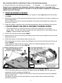
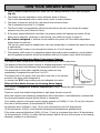
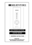
REDRING DASH RANGE SMARTFIT ELECTRIC SHOWERS Installation and User Guide IMPORTANT: This booklet should be left with the user after installation and demonstration. IMPORTANT SAFETY INFORMATION THIS APPLIANCE CAN BE USED BY CHILDREN AGED FROM 8 YEARS AND ABOVE AND PERSONS WITH REDUCED PHYSICAL, SENSORY OR MENTAL CAPABILITIES, OR LACK OF EXPERIENCE AND KNOWLEDGE IF THEY HAVE BEEN GIVEN SUPERVISION OR INSTRUCTION CONCERNING USE OF THE APPLIANCE IN A SAFE WAY AND UNDERSTAND THE HAZARDS INVOLVED. CHILDREN SHALL NOT PLAY WITH THE APPLIANCE. CLEANING AND USER MAINTENANCE SHALL NOT BE MADE BY CHILDREN YOU MUST DESCALE THE SHOWER HANDSET REGULARLY. DO NOT SWITCH THE APPLIANCE ON IF YOU SUSPECT THE APPLIANCE OF BEING FROZEN. WAIT UNTIL YOU ARE SURE IT HAS THAWED OUT. Your shower has been designed for convenience, economy and safety of use, provided that it is installed, used and maintained in good working order and in accordance with our instructions and recommendations. ALL WIRING AND INSTALLATION MUST BE SUPERVISED BY A SUITABLY QUALIFIED PERSON. THIS APPLIANCE MUST BE EARTHED. The installation must be in accordance with the current edition of BS.7671 (the ‘IET Wiring Regulations’) and ‘Part P’ of the ‘Building Regulations’ in force at the time of installation. Installations outside England and Wales must also conform to any local regulations in effect This appliance is intended to be permanently connected to the fixed electrical wiring of the mains supply with its own dedicated supply. This appliance must NOT be fitted where it may be subjected to freezing conditions. DO NOT switch the appliance on if you suspect it of being frozen. Wait until you are sure it has thawed out. This appliance is not suitable for mounting into steam rooms or steam cubicles. Isolate the mains electrical and water supply before removing the appliance front cover. DO NOT fit any sort of tap or control on the appliance outlet. The appliance is designed to have an open outlet and should only be used with the Manufacturer’s recommended fittings. THIS SHOWER IS APPROVED (EN-60335) WITH THE HANDSET PROVIDED AND UNDER NO CIRCUMSTANCES MUST ANY HANDSET THAT IS NOT APPROVED BY THE MANUFACTURER BE USED WITH THIS PRODUCT. YOU MUST REGULARLY INSPECT THE HANDSET FOR WEAR AND DAMAGE AND REPLACE IF NECESSARY, WITH OUR APPROVED PART. Take care to avoid restricting the outlet of the pressure relief device (fig.12). If water is discharged from the pressure relief device, maintenance will be required before the appliance can be safely used. We DO NOT recommend this appliance be used in heavy or unsupervised commercial applications. 2 ADVICE TO USERS The following points will help you have a greater understanding of how your shower works: The heating elements operate at a constant rate, dependent on your chosen power setting. The water temperature is achieved by adjusting the rate of water flow. The higher the water flow the lower the temperature and vice versa. The temperature of the water supplied from the mains can vary considerably throughout the year from 5 to 20°C. This means that in the winter, flow rate will be less than in the summer to achieve the same outlet temperature. In summer the ‘ECO’ power setting may give adequate hot water. Your shower is designed to stabilise temperature changes caused by water pressure fluctuations. These can result from toilets being flushed or taps being turned on and off. When this happens your showering temperature will be held within a controlled band, provided that the minimum pressure required by the shower is maintained (see ‘plumbing’ page.5). If the water pressure falls below the minimum pressure required, it is likely that the pressure switch will turn off the power to the heating elements, resulting in a cold shower. HOW TO INSTALL YOUR SHOWER WARNING: ALL WIRING AND INSTALLATION MUST BE SUPERVISED BY A SUITABLY QUALIFIED PERSON. DO NOT INSTALL THIS SHOWER WHERE IT MAY BE SUBJECTED TO FREEZING CONDITIONS. 1 3 We recommend that the installation is done in the following sequence. a. Fixing the shower to the wall (see note below) b. Plumbing c. Electrical connections However, we recommend you determine the best configuration for your water inlet options before fixing the shower to the wall, as it may be easier to adjust/fit connections whilst unit is still ‘in-hand’. a. FIXING THE SHOWER TO THE WALL 1. Position the riser rail at a convenient height for majority of users (fig.1) and mark its position (see fig.8). 2. Position the shower unit so that the showerhead cannot be immersed in the bath or shower tray when hanging down. Choose a flat piece of wall to avoid the possibility of distorting the backplate thus making the front cover a poor fit. 3. Adjust the position to get the most convenient arrangement taking the following into account. DO NOT MOUNT THE UNIT IN THE DIRECT HANDSET SPRAY. The handset must not be able to come into contact with used water in the cubicle, bath or basin. If it can, even after the hose has been retained by the hose-retainer feature (fig.8), a vacuum breaker must be fitted. 4. Fix the riser rail with screws provided (fig.8) 5. Remove the front cover by undoing the retaining screws at the top and bottom of the unit and lifting the cover off. 6. Decide the position of the electrical cable into the unit. If the top entries are chosen, remove the cable/pipe entry from fixing kit bag and cut away as shown (fig.2a). If rear, bottom or side entries are chosen, remove the relevant cable/pipe entry from the detachable lower section as shown (fig.2b). 2a 2b 7. Your shower is provided with 6 x wall-fixing positions in the backplate (fig.12) The 3 x top-fixing holes are a ‘key-hole’ slot design (‘a’ or ‘m’ fig.12), and the single most convenient should be marked and drilled first. Tighten fixing screw with head protruding about 10mm from the wall and hook the backplate over the screw head. This allows for correct and accurate alignment of your shower before marking and fixing the bottom positions. 4 Mark and drill the other 2 x most convenient wall fixing slots (‘f’ fig.12), ensuring the slot in the detachable lower backplate section is used. Remove the detachable lower section by lifting away from the 2 x fixing posts/pegs (fig.3). Tighten fixing screw in main shower, leaving the detachable lower section screw until later. You may wish to leave both fixing screws loose At this stage, as the holes are elongated to allow for adjustment after other connections have taken place. 3 b. PLUMBING WARNING: ENSURE THAT THE MAINS WATER SUPPLY MEETS THE REQUIREMENTS BELOW BEFORE CONTINUING INSTALLATION. The shower unit must be connected to the mains cold water supply. This must have a minimum supply running pressure of 100kPa (1.0 bar, 15 psi) at a minimum flow rate of 8 litres/minute*. The maximum static supply pressure must be no greater than 1000kPa (10 bar, 150 psi). * Minimum running pressure must be obtained at 9 litres/minute for 9.5kW. WARNING: BEFORE CONNECTING THE PIPE WORK TO THE SHOWER, ENSURE THAT THE PIPE WORK IS FULLY FLUSHED OUT. 1. It is recommended that a WRAS (Water Regulations Advisory Scheme) listed isolating valve is fitted to the incoming mains cold water before the shower unit. This will allow the unit to be serviced or exchanged without having to turn off the water at the water stop valve. 2. The water inlet connection supplied is a plain Ø15mm straight shank/shaft. Connect the mains water supply to the shower using Ø15mm copper pipe (BS.EN.1057) or Ø15mm plastic pipe (with insert). We recommend the use of copper olives. If you choose to use a ‘push-on’ connection, DO NOT use stainless steel or chrome plated pipe. In multiple installations, calculate correct pipe work sizes to maintain adequate flow to each unit. WATER INLET ENTRY OPTIONS (also see fig.4). The pipe work can enter the shower unit from 6 x different positions, depending on the fitting. Side Right, Side Left, Top Right, Top Left, Bottom Right or Bottom Left. These is also the option to have a rear water entry by swivelling the fitting to face a rear entry pipe connection. If the pipe work entry is from the rear, ensure there is enough space left around the fitting for future servicing or alternatively access is possible from the rear. An additional ‘Yorkshire’ elbow (soldered type) for fitting on the rear channel of the backplate is also suitable (fig.4c) 3. It is permissible to use a WRAS (Water Regulations Advisory Scheme) approved sealant sparingly, avoiding excess finding its way into the shower operating parts. 4. With the isolating valve connected, flush the pipe work through to remove any particles etc, before making the final connection to the shower. Water way blockages (particularly in handset and filter) will prevent the unit working properly. Note: You may be charged for a service call if it is due to incorrect installation. 5 4b b 4a 2 6 4c 5b 2 5. The shower is designed to have an open outlet and should only be used with the manufacturers recommended fittings. Do not connect the handset until the shower front cover and detachable lower section are fitted. WARNING: DO NOT FIT A TAP ON THE SHOWER OUTLET. TAKE CARE TO AVOID RESTRICTING THE OUTLET OF THE PRESSURE RELIEF DEVICE. c) ELECTRICAL WARNING: THIS SHOWER MUST BE EARTHED. The electrical installation must be in accordance with the current BS.7671 (IET Wiring Regulations) and ‘Part P’ of the Building Regulations and/or local regulations 1. The shower unit is designed for a single phase AC electrical supply. Please check the rating plate on the unit to see what details apply to your shower. Rating 7.2 / 6.6kW 240 / 230V 8.5 / 7.8kW and 9.5 / 8.7kW 240 / 230V Cable Sizes Fuse / MCB Cable Length 4.0mm² 6.0mm² 32A Type B MCB 21m Max. 35m Max. 6.0mm² 10.0mm² 40A Type B MCB 27m Max. 45m Max. 6.0mm² 10.0mm² 40A Type B MCB 27m Max. 45m Max. 6.0mm² 10.0mm² 45A BS.1361 fuse 12m Max.* 21m Max.* AS A GUIDE ONLY (* Only applies if external earth impedance is less than 0.35 Ohms) Upgrade the cable if it runs in thermal insulation in a loft, or for longer distances. 2. A means for disconnection in all poles must be incorporated in the fixed wiring in accordance with the wiring rules. We recommend a ceiling switch mounted in a convenient position. 3. Cut back cable (fig.5). Connect cable to terminal block making sure that all the retaining screws are VERY TIGHT and that no cable insulation is trapped under the screws. WARNING: FAILURE TO COMPLY WITH THESE INSTRUCTIONS COULD RESULT IN FAILURE OF THE TERMINAL BLOCK 5 4. Refit the detachable lower section onto the backplate ensuring it is firmly located over the 2 x fixing posts/pegs (fig.3), and tighten the wall fixing screw. WARNING: PLEASE NOTE THAT THE DETACHABLE LOWER SECTION MUST BE SECURED TO THE WALL USING THE FIXING POSITION PROVIDED. 7 WARNING: KNOB ALIGNMENT IS VERY IMPORTANT DURING THE INSTALLATION OF YOUR SHOWER AND MUST BE CORRECT FOR CORRECT OPERATION. 5. Ensure Power Select Knob is aligned to the ‘COLD’ (9 o‘clock) position, whilst the ‘D-Shaft’ in the product is aligned as shown (fig.6). 6 6 6. Ensure Temperature Control Knob is aligned to the ‘STOP’ position, whilst the ‘spindle’ in the product is rotated fully clockwise as shown (fig.7). 7 7 7. Fully tighten all wall fixing screws. 8. Refit the front cover, and secure by replacing the top and bottom fastening screws. 9. Ensure that the Power Selection Knob has been correctly aligned by ensuring that all 3 power settings can be selected. 10. Ensure that temperature knob has been correctly aligned by turning from minimum to maximum flow (more than 1 full turn), the knob should return to the ‘STOP’ position. COMMISSIONING PROCEDURE. WARNING: BEFORE NORMAL OPERATION, IT IS ESSENTIAL THE FOLLOWING COMMISSIONING PROCEDURE IS COMPLETED CORRECTLY. This procedure is to make sure the shower contains water before the heating elements are turned on This operation MUST be carried out WITH the flexible hose screwed to the shower outlet pipe with the sealing washer in place but WITHOUT THE SHOWER HANDSET ATTACHED. Make sure the outlet of the flexible hose is directed to waste. The mains electricity supply MUST be SWITCHED OFF during the commissioning procedure. The shower has a mechanical shut-off valve, as opposed to an electronic design, and supplying power during commissioning may damage the unit. a) Before turning on the mains water supply to the shower, make sure the Power Selection Knob is at the ‘COLD’ position (fig.6) and check the Temperature Selection Knob is turned fully clockwise to the ‘STOP’ position (fig.7). b) Turn on the mains water supply to the shower at the isolating valve. 8 c) Slowly rotate the Temperature Selection Knob anti-clockwise until it stops and wait until water starts to flow from the flexible hose. It will take about thirty seconds for a smooth flow of water to be obtained while air and any debris is flushed from the shower. d) When a smooth flow of water is obtained, slowly rotate the Temperature Selection Knob from Minimum to Maximum several times to release any air trapped within the unit. e) Once flushing out has been completed, stop the water flow by turning the Temperature Selection Knob fully clockwise to the ‘STOP’ position (fig.7). The shower is now ready for normal operation (when mains electricity is switched on). 11. If you have not yet done so, assemble your Shower Accessories (fig.8). Fit the seal washer into the shower hose nut and then fit the handset. 12. Operate the shower as in ‘How to operate your shower’ section, then please check: That the water gets to a satisfactory temperature and water flow can be adjusted by the Temperature Selection Knob. That the Power Selection Knob operates in all 3 positions. Check again for leaks. That the holes in the shower handset are not blocked. 13. DEMONSTRATE OPERATION TO USERS, AND LEAVE THIS BOOK WITH THEM FOR FUTURE REFERENCE. SHOWER ACCESSORIES ASSEMBLY. 8 9 HOW TO OPERATE YOUR SHOWER Ensure the electricity and water are turned on. 9 Your shower has 2 control knobs (fig.9). Knob ‘A’ - starts and stops the shower and controls the water temperature. Knob ‘B’ - controls the 3 x power selection ‘HIGH’ ‘ECO’ ‘COLD’ TO START THE SHOWER Rotate Knob ‘A’ anti-clockwise and select the ‘Number 6’ position. Water will start to flow. Set your desired power setting Knob ‘B’, this is normally ‘HIGH’. It is recommended that you do not wholly enter the water spray during this period, especially if the shower has just been used. If the water is not at your desired temperature, turn Knob ‘A’ a small amount until the desired temperature is achieved (fig.10a/b). Turn clockwise to a ‘Higher Number’ for warmer. 10a Turn anti-clockwise to a ‘Lower Number’ for cooler. The final adjustment may be anywhere on the scale. 10b Allow about 20 seconds for the temperature of the water to stabilise. Final adjustment may be anywhere on the scale and may not line up directly with a number. If after turning fully anti-clockwise, water is still too hot, adjust Knob ‘B’ to ‘ECO’ setting and re-adjust as previously detailed. Please note that the water flow will be reduced on this setting. TO STOP THE SHOWER Rotate Knob ‘A’ clockwise to the ‘STOP’ position (fig.11). You have no need to adjust Knob ‘B’. Water will cease to flow. Switch off the electricity at the ceiling switch or local isolator. The position of Knob ‘A’ will be approximately the same each time 11 the shower is used. You must however take into account required adjustments for variations of incoming mains water temperature between summer and winter (see ‘Advice to users’ on page.2). The ‘ECO’ setting of Knob ‘B’ reduces the power used by the shower giving a cooler shower or the option of reduced water flow. This option is mainly for summer usage and if this is used then Knob ‘B’, must be re-adjusted. The ‘COLD’ setting of Knob ‘B’ will supply water without any heating. During normal operation, if an overheated water temperature is sensed then the heating elements will be switched off. Water will continue to flow and cool down before the heater switches back on again as the heater automatically resets itself when water has been run through the shower for a few seconds. 10 WARNING: DO NOT SWITCH THE SHOWER ON IF YOU SUSPECT IT OF BEING FROZEN. WAIT UNTIL YOU ARE SURE IT HAS THAWED OUT. DO NOT OPERATE THE SHOWER IF WATER IS DISCHARGED FROM THE PRESSURE RELIEF VALVE. MAINTENANCE IS REQUIRED BEFORE IT CAN BE USED AGAIN. CONSIDERATION SHOULD BE GIVEN TO SUPERVISING THE YOUNG, ELDERLY AND THE INFIRM WHILST THEY USE THIS SHOWER. AFTER SALES SERVICE We offer a technical advisory service on the telephone to installers and other customers with problems in the field. Please call our technical team on: Or alternatively email us on: 0844 372 7766 [email protected] Remember to quote the exact type of shower, as written on the front of the shower and on this leaflet. The model and serial number are located on the bottom face of the shower. Make a note of those numbers here, and be sure to quote them if you call for advice. Model Number: 5356 . . . . . . . . . . . . Serial Number: ................ NOTE: You may be charged for a service call if you do not have the serial number. ENERGY RELATED PRODUCT DIRECTIVE (ErP) This information shows how our products pass the relevant European Union Energy Directives (ErP) Manufacturer Product Redring RDS95 RDS85 RDS75 Load Profile XS XS XS Efficiency Class A A A Efficiency % 38 39 39 Consumption (kWh / annum) 812 814 816 Sound (dB) 15 15 15 Precautions Please ensure all product installation, maintenance and care instructions are followed as listed in this booklet 11 WHAT TO DO IF THINGS GO WRONG (1) SELF HELP If the shower is not working satisfactorily, make the following checks before calling out the installer. Any one of these adjustments could restore the performance. Shower cycles from HOT to COLD The shower temperature is set too hot causing the thermal cut-out (safety device) to operate. Turn Knob ‘A’ anti-clockwise towards ‘Number.1’ to increase water flow. Then slowly increase the water temperature by turning Knob ‘A’ clockwise towards ‘Number.9’ until a comfortable showering temperature has been reached. You MUST WAIT approximately 20 seconds for each adjustment to affect the water temperature. ‘ECO’ setting may need to be selected. Water too HOT Increase water flow by adjusting Knob ‘A’ anti-clockwise towards ‘Number.1’. ‘ECO’ setting may need to be selected. Increase pressure to water supply. Fully open service valve/stop cock. Check hose is not kinked restricting the water flow. Clean handset. Check and clean filter if necessary. Water too COLD Decrease water flow by adjusting Knob ‘A’ clockwise towards ‘Number.9’. ‘HIGH’ setting may need to be selected. Water takes longer to heat up Water goes cold whilst using shower Poor Spray Broken parts Thermal cut-out has operated after previous use (automatically resets when unit cools down). ‘HIGH’ setting may need to be selected. Check water pressure has not fallen so far as to let the pressure switch cut out, e.g. another tap drawing water off. Clean the shower handset. Please contact our after sales service department (see page.11). 12 WHAT TO DO IF THINGS GO WRONG (2) PROFESSIONAL SERVICE If the previous ‘Self Help’ checks fail to restore the performance, you should seek professional help. The person who installed the shower is probably the best one to investigate and correct it and is certainly the person to contact if you have had a problem in the guarantee period. The following additional checklist is provided for the benefit of the qualified service person. WARNING: SWITCH OFF THE ELECTRICITY AND MAINS WATER SUPPLY AT THE LOCAL ISOLATOR BEFORE REMOVING THE COVER TO MAKE CHECKS. Water too HOT Water flow restricted by blockage in filter. Switch off water, remove filter and flush clean. Water too COLD Check Check Check Check No water flow control Water discharge from pressure relief valve circuit through thermal cut-out. circuit through microswitches on the pressure switch. each element circuit. tightness of electrical connections. Undo headworks of stabiliser valve Check stabiliser is in place and remove any debris in valve. Check for cause of high pressure and remove it. Blockage on outlet e.g. blocked shower handset. Replace the pressure relief device. HOW TO MAINTAIN YOUR SHOWER It is recommended that the shower unit and accessories be cleaned using a soft cloth and that the use of abrasive or solvent based cleaning fluid be avoided, especially on any plated finishes. We recommend that before any cleaning, the isolating switch be turned off, thus avoiding accidentally switching on the shower. All water contains particles of lime-scale, which build up in the handset and unit reducing the performance. It is therefore important to clean the handset by simply rubbing the rubber nozzles, or soaking in a proprietary lime-scale remover and rinsing thoroughly before use. NOTE: After use it is normal for some water to drip from the handset for a few moments. This inhibits lime-scale build-up over prolonged use. WARNING: YOU MUST REGULARLY INSPECT THE SHOWER HOSE FOR WEAR AND DAMAGE AND REPLACE IF NECESSARY, OR EVERY 2 YEARS, WITH OUR APPROVED PART. IN ORDER TO MAINTAIN THE PERFORMANCE OF YOUR SHOWER, YOU MUST CLEAN THE SHOWER HANDSET REGULARLY. YOU MUST REGULARLY INSPECT THE HANDSET FOR WEAR AND DAMAGE AND REPLACE IF NECESSARY, WITH OUR APPROVED PART. 13 HOW YOUR SHOWER WORKS 1. Water is heated instantaneously as it flows over the heating elements in the heat exchanger (fig.12). 2. The heaters are only switched on when sufficient water is flowing. This is done automatically with a switch which works on water pressure. 3. The water is turned on and off by a tap that is built into the shower. This is activated when Knob ‘A’ is rotated. 4. The flow of water is automatically held at the level set by the user even though the supply pressure may vary (see ‘Advice to Users’). 5. If the water supply falls below a set limit, the pressure switch will operate and switch off the power to the elements, resulting in a cold shower (see ‘Advice to Users’ on page.2). 6. As a further safeguard, a thermal cut-out switches the power off if the water temperature climbs above the set limit. This cut-out, which gives an audible click, may also operate due to residual heat when the shower is switched off. It will reset itself if water is run through the shower for 10 to 20 seconds. 7. The pressure relief device is to safeguard against abnormal pressure conditions, and provides a level of appliance protection should an excessive build up of pressure occur within the shower. Effect of Seasonal Incoming Water Temperature Changes The required water temperature is achieved by adjusting the rate of water flow. The diagram shows the principle involved in relating temperature rise to flow rate. The higher the water rate the lower the temperature and vice versa. The temperature of the water supplied from the mains can vary considerably throughout the year from 5 to 20°C. This means that in the winter, flow rate will be less than in the summer to achieve the same outlet temperature. In summer the ‘ECO’ power setting may give adequate hot water. Effect of Other Water Devices on Incoming Water Supply Your shower is designed to stabilise temperature changes caused by water pressure fluctuations. These can result from toilets being flushed or taps being turned on and off. When this happens your showering temperature will be held within a controlled band, provided that the minimum pressure required by the shower is maintained. Your shower requires a minimum running supply pressure of 100kPa (1.0 bar, 15 psi) at a minimum flow rate of 8 litres/minute (9 litres/minute for 9.5kW). At pressures above 100kPa (1.0 bar, 15 psi) at a minimum flow rate of 8 litres/minute. (9 litres/minute for 9.5kW), it will minimise temperature fluctuations as detailed above. If the water pressure falls below 100kPa (1.0 bar, 15 psi) at a minimum flow rate of 8 litres/minute, (9 litres/minute for 9.5kW), it is likely that the pressure switch will turn off the power to the heating elements, resulting in a cold shower. 14 MAIN SHOWER COMPONENTS CIRCUIT DIAGRAM 12 a) Wall Fixing Key-Hole Slot h) Detachable Lower Backplate Section b) Thermal Cut-Out c) Heat Exchanger i) j) Inlet Filter Water Inlet d) Flow Valve k) Terminal Block e) Pressure Relief Device l) Pressure Switch f) m) Alternative Wall Fixing Key-Hole Slot Wall Fixing Slot g) Water Outlet COMMON SPARE PARTS Please Note:- The fitting of Spare Parts must be supervised by a suitably qualified person. Front Cover Assembly Cat No. 93672190 Power Select Knob Cat No. 93672167 Thermal Cut-Out Cat No. 93672109 Temperature Select Knob Cat No. 93672168 1.0m Chrome Shower Hose Cat No. 93672120 Pressure Relief Device Cat No. 93672107 Handset (White) Cat No. 93672129 Pressure Switch Assembly Cat No. 93672124 Lower Section Cat No. 93672177 Tank Clip Cat No. 93672106 Ø18mm Height Adjuster Cat No. 93590744 Ø18mm White Soap-Dish Cat No. 93768378 Ø18mm Riser Rail Cat No. 93593533 Ø18mm Riser Rail Brackets Cat No. 93795877 15 GUARANTEE Terms and Conditions for UK (outside UK contact your local distributor) In the unlikely event of a product breakdown during the guarantee period you should contact our Service and Repair Helpline who will be able to assist with the repair and advise of the best course of action to be taken. Please DO NOT remove the product prior to making this call as this may invalidate your guarantee. Service and Repair Tel: 0844 372 7766 or email: [email protected] We guarantee this product for domestic use only, for a period of 24 months from the date of purchase. Within the guarantee period we will resolve, free of charge, any manufacturing defects in the product resulting from faulty workmanship or material on condition that:a) The product has been correctly installed and commissioned in accordance with our instructions and is being used on the supply circuit or voltage printed on the rating plate. b) The product has been used in accordance with these instructions and has not been tampered with or otherwise subject to misuse, neglect or accident. c) The product has not been taken apart, modified or repaired except by a person authorised by us. d) Evidence of the date of purchase in the form of an invoice or receipt will be required in order to qualify under the terms of this guarantee. e) The guarantee period for products used in light commercial applications will be limited to 12 months. We DO NOT recommend these products be used in heavy or unsupervised commercial applications. f) For the service work to be undertaken free of charge, the work must only be undertaken by Redring Xpelair Group Limited, or our approved agents. g) Service under guarantee has no effect on the expiry date. The guarantee on any exchanged parts or product ends when the original guarantee period ends. EXCLUSIONS This guarantee DOES NOT cover damage or defects arising from poor or incorrect installation, improper use or lack of maintenance, including the build-up of limescale. It is the responsibility of the installer to check that the installation parameters meet the requirements of the products, and any relevant regulations. If we are called out to a fault, which is subsequently identified as being an installation fault, we will make a charge. It is important that the routine checks are completed before calling us out, as many issues can be simply diagnosed and resolved. A charge will be made where a call under the terms of the guarantee has been booked and a failure was not product related, or an engineer arrives and is not able to gain access. We make no guarantees as to response time for repairs. We will endeavour to achieve the most timely response possible but while we indicate an average response time, this should not be taken as a guarantee. The guarantee applies to a repair or replacement (at our discretion) of the product subject to the conditions above, and DOES NOT cover compensation for the loss of the product or consequential loss of any kind. This guarantee does not apply to the repair or replacement of pressure relief devices, sprayheads, hoses, accessories, isolating switches, electrical cable, fuses and/or circuit breakers. This guarantee does not affect your statutory rights. Newcombe House, Newcombe Way, Orton Southgate, Peterborough, PE2 6SE Tel: +44 (0) 844 372 7761 / Fax: +44 (0) 844 372 7762 Technical Service Tel: +44 (0) 844 372 7766 Technical Service Email: [email protected] 16 (A4 Leaflet No. 556-2097-01a)