1
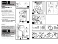
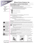
GUARANTEE Terms and Conditions for UK (outside UK contact your local distributor) In the unlikely event of a product breakdown during the guarantee period, you should contact our Service and Repair Helpline who will be able to assist with the repair and advise of the best course of action to be taken. Please DO NOT remove the product prior to making this call as this may invalidate your guarantee. Service and Repair Tel: 0844 372 7766 or email: [email protected] We guarantee this product for a period of 12 months from the date of purchase. Within the guarantee period we will resolve, free of charge, any manufacturing defects in the product resulting from faulty workmanship or material on condition that:a) The product has been correctly installed and commissioned in accordance with our instructions and is being used on the supply circuit or voltage printed on the rating plate. b) The product has been used in accordance with these instructions and has not been tampered with or otherwise subject to misuse, neglect or accident. c) The product has not been taken apart, modified or repaired except by a person authorised by us. d) Evidence of the date of purchase in the form of an invoice or receipt will be required in order to qualify under the terms of this guarantee. e) For the service work to be undertaken free of charge, the work must only be undertaken by Redring Xpelair Group Limited, or our approved agents. f) Service under guarantee has no effect on the expiry date. The guarantee on any exchanged parts or product ends when the original guarantee period ends. EXCLUSIONS This guarantee DOES NOT cover damage or defects arising from poor or incorrect installation, improper use or lack of maintenance, including the build-up of limescale. It is the responsibility of the installer to check that the installation parameters meet the requirements of the products, and any relevant regulations. If we are called out to a fault, which is subsequently identified as being an installation fault, we will make a charge. It is important that the routine checks are completed before calling us out, as many issues can be simply diagnosed and resolved. A charge will be made where a call under the terms of the guarantee has been booked and a failure was not product related, or an engineer arrives and is not able to gain access. We make no guarantees as to response time for repairs. We will endeavour to achieve the most timely response possible but while we indicate an average response time, this should not be taken as a guarantee. INSTANT I3V The guarantee applies to a repair or replacement (at our discretion) of the product subject to the conditions above, and DOES NOT cover compensation for the loss of the product or consequential loss of any kind. MANUAL ELECTRIC HANDWASH This guarantee does not apply to the repair or replacement of pressure relief devices, sprayheads, isolating switches, electrical cable, fuses and/or circuit breakers. This guarantee does not affect your statutory rights. IMPORTANT: This booklet should be left with the user after installation and demonstration. Newcombe House, Newcombe Way, Orton Southgate, Peterborough, PE2 6SE Tel: +44 (0) 844 372 7761 Fax: +44 (0) 844 372 7762 Technical Service Tel: +44 (0) 844 372 7766 Technical Service Email: [email protected] 8 Installation and User Guide (A4 Leaflet: 567-2613-01a) THIS APPLIANCE CAN BE USED BY CHILDREN AGED FROM 8 YEARS AND ABOVE AND PERSONS WITH REDUCED PHYSICAL, SENSORY OR MENTAL CAPABILITIES, OR LACK OF EXPERIENCE AND KNOWLEDGE IF THEY HAVE BEEN GIVEN SUPERVISION OR INSTRUCTION CONCERNING USE OF THE APPLIANCE IN A SAFE WAY AND UNDERSTAND THE HAZARDS INVOLVED. CHILDREN SHALL NOT PLAY WITH THE APPLIANCE. CLEANING AND USER MAINTENANCE SHALL NOT BE MADE BY CHILDREN DO NOT SWITCH THE APPLIANCE ON IF YOU SUSPECT THE APPLIANCE OF BEING FROZEN. WAIT UNTIL YOU ARE SURE IT HAS THAWED OUT. 3b. If the water is too cold, then decrease the water flow by, Turning the control knob clockwise, and continue as necessary until you get the water temperature of your liking (fig.H). The final adjustment may be anywhere on the scale. WARNING: BEFORE ANY CLEANING, SWITCH OFF AT THE ISOLATING SWITCH. CLEANING AND MAINTENANCE SHALL NOT BE MADE BY CHILDREN 3c. Basically turning the control knob clockwise increases water temperature anti-clockwise decreases the temperature Wait a few moments for the temperature of the water to stabilise. 4. The neon indicator on the front of the handwash shows when the heating element is working. It is recommend that the handwash unit be cleaned using a soft cloth and that the use of abrasive or solvent cleaning fluid be avoided. The patented “Vortex” spray head does not require de-scaling. 5. When you have finished handwashing, turn the control knob fully clockwise to the off position. 6. DEMONSTRATE OPERATION TO USERS, Your handwash unit has been designed for convenience, economy and safety of use, provided that it is installed, used and maintained in good working order and in accordance with our instructions and recommendations. The following points will help you have a greater understanding of how your handwash works: The electric heating element operates at a constant rate. The required water temperature is achieved by adjusting the rate of water flow. The higher the water flow the lower the temperature and vice versa. The temperature of the water supplied from the mains can vary considerably throughout the year from 5 to 20°C. This means that in the winter, flow rate will be less than in the summer to achieve the same outlet temperature. Your handwash is designed to work within a range of water pressures, if the pressure falls below the minimum pressure required, it is likely that the pressure switch will turn off the power to the heating element, resulting in cold water being produced by the unit. (see page 3 for details) ALL WIRING AND INSTALLATION MUST BE SUPERVISED BY A SUITABLY QUALIFIED PERSON. THIS APPLIANCE MUST BE EARTHED. The installation must be in accordance with the current edition of BS.7671 (the ‘IET Wiring Regulations’) and ‘Part P’ of the ‘Building Regulations’ in force at the time of installation. Installations outside England and Wales must also conform to any local regulations in effect This appliance is intended to be permanently connected to the fixed electrical wiring of the mains supply with its own dedicated supply. This appliance must NOT be fitted where it may be subjected to freezing conditions. Isolate the mains electrical and water supply before removing the appliance front cover. DO NOT fit any sort of tap or control on the appliance outlet. Take care to avoid restricting the outlet of the pressure relief device (fig.C). If water is discharged from the pressure relief device, maintenance will be required before the appliance can be safely used. AND LEAVE THIS BOOK WITH THEM FOR FUTURE REFERENCE. WARNING: DO NOT SWITCH THE UNIT ON IF YOU SUSPECT IT OF BEING FROZEN. WAIT UNTIL YOU ARE SURE IT HAS THAWED OUT. WARNING: CONSIDERATION SHOULD BE GIVEN TO SUPERVISING THE YOUNG, ELDERLY AND THE INFIRM WHILST THEY USE THIS UNIT. We offer a technical advisory service on the telephone to installers and other customers with problems in the field. Please call our technical team on: 0844 372 7766 Or alternatively email us on: [email protected] Remember to quote the exact type of handwash, as written on the front of the unit and on this leaflet. The model and serial number are located on the bottom face of the handwash. Make a note of those numbers here, and be sure to quote them if you call for advice. Model Number: . . . . . . . . . . . . . . . . . . . . . . . . . . . . . . . . Serial Number: . . . . . . . . . . . . . . . . . . . . . . . . . . . . . . . . NOTE: You may be charged for a service call if you do not have the serial number. 2 7 4. Check that the water flows freely from the handwash within a few seconds. The water from the patented ‘Vortex’ sprayhead will be at full force and at a cool temperature. 5. Rotate the control knob slowly clockwise. This will gradually reduce the water flow with the water temperature remaining cool. It is necessary to engage the control knob in the correct position on the flow valve spindle before the front cover is located. 6. Rotate the control knob fully anti-clockwise to return to maximum water flow. 1. Ensure the 2 x backplate fixing screws are fully tightened (fig.B). 7. Switch on the mains electrical supply at the isolating switch. The ‘Power’ neon indicator will illuminate. 2. Before replacing the front cover, check that the flow valve spindle and the control knob are rotated fully clockwise (fig.G). 8. Turn the control knob clockwise and check that the water gets warmer, Turn anti-clockwise and check the water gets cooler. 3. Refit the front cover with the 3 x fixing screws DO NOT switch on the power to the handwash unit until the commissioning procedure has been carried out. Wait a few moments for the temperature of the water to stabilise. IMPORTANT: Turn the control knob fully anti-clockwise until the valve is fully open. This will ensure a fast fill up of the handwash. NOTE: When the water temperature is changed the flow rate alters. 9. Turn the control knob fully clockwise to stop the water flow. Let the water flow through the handwash unit to release any air which may be in the system and fill the handwash with water. IMPORTANT: When a steady water flow is evident, turn the control knob fully clockwise to the off position. 1. The mains electricity and water supply should normally be left on. The flow of the water is controlled by a tap, which is incorporated inside the unit. 2. Turn the knob anti-clockwise 180° (fig.H). This will, in the majority of cases, provide a suitable temperature for washing hands. However, in extreme conditions, i.e. mid-winter or mid-summer, the temperature of the water can be adjusted to suit. IMPORTANT: The handwash unit must be full of water before the power is switched on. 1. Make sure that the electrical supply has been isolated at the isolating switch. 3a. If the water is too hot, then increase the water flow by, Turning the control knob anti-clockwise Wait a few moments for the temperature of the water to stabilise (fig.H). Repeat turning anti-clockwise if necessary until you get the water temperature of your liking. 2. Ensure the water supply is fully on at the mains and the isolating service valve (if fitted) is fully open, check that water is not leaking from the bottom of the case. 3. Turn the control knob anti-clockwise to the full cold position. 6 1. Remove the three screws securing the handwash unit cover and remove the cover complete with the control knob. 2. Place the handwash unit on the wall and determine the entry position of the water inlet supply pipe. Ø15mm copper, chrome polished or stainless steel pipe should be used. Ensure that there are no burrs on the pipe. In multiple handwash installations, correct pipe work sizes should be calculated to maintain adequate flow to each unit. Plan your own installation carefully. Check on the nearest and most readily accessible rising mains water supply. The unit should be sited so that all the spray is contained in the sink (fig.A) 3. Mark the location of the fixing screws through the backplate (fig.B). A ‘keyhole slot provided on the top fixing hole to assist installation, and should be marked and drilled first to take the wall plugs and screws provided. We recommend that a WRAS (Water Regulations Advisory Scheme) listed isolating valve is fitted into the mains cold water supply for servicing purposes. WARNING: ALL WIRING AND INSTALLATION MUST BE SUPERVISED BY A SUITABLY QUALIFIED PERSON. DO NOT INSTALL THIS UNIT WHERE IT MAY BE SUBJECTED TO FREEZING CONDITIONS. USE ONLY THE COLD RISING WATER MAIN SUPPLY. DO NOT CONNECT THE HANDWASH UNIT TO THE DOWN SERVICE FROM A COLD WATER STORAGE TANK. 4. Tighten the top screw with head protruding about 10mm from the wall and hook the backplate over the screw head. This allows for correct and accurate alignment of the handwash unit before fixing the bottom position. You may not wish to tighten up both screws at this stage as the holes are elongated to allow for adjustment after other connections have been made 5. Before completing the connection of the water supply to the inlet of the unit, ensure you flush out the pipework to remove all swarf and system debris. 6. Connect the mains water supply to the inlet of the handwash unit using the relevant Ø15mm pipe. Do not use excessive force when making the connection to the unit. We recommend you support the outlet with a spanner (fig.D) 7. It is permissible to use a WRAS (Water Regulations Advisory Scheme) approved sealant sparingly whilst avoiding excess finding its way into the handwash operating parts. Plumbing the handwash unit must precede making electrical connections. The handwash unit must be connected to the cold water supply with a minimum running pressure of 69 kPa (0.7 bar, 10 psi) and a maximum pressure of 690 kPa (7.0 bar, 100 psi). WARNING: TAKE CARE TO AVOID RESTRICTING THE OUTLET OF THE PRESSURE RELIEF DEVICE. Turn off the water supply at the isolating tap. Before removing the front cover, check that the control knob is set to off - 12 o’clock fully clockwise. 3 A WARNING: THIS HANDWASH MUST BE EARTHED. The electrical installation must be in accordance with the current BS.7671 (IET Wiring Regulations) and ‘Part P’ of the Building Regulations and/or local regulations 1. The handwash unit is designed for a single phase AC electrical supply. D F 2. Use 3-Core 1.5mm² double insulated cable. The cable can be surface clipped, hidden or via conduit. 2. The incoming cable access to the handwash unit must be via the two bottom, the top, or rear channels provided in the backplate (fig.C) 3. Cut back cable (fig.E). Connect cable to terminal block making sure that all the retaining screws are VERY TIGHT and that no cable insulation is trapped under the screws. B 4. Ensure the cable clamp is used to secure the cable into position. E WARNING: FAILURE TO COMPLY WITH THESE INSTRUCTIONS COULD RESULT IN FAILURE OF THE TERMINAL BLOCK G IMPORTANT: Fitting the swivel arm must precede fitting the front cover 1. Ensure the rubber ‘O’-ring is located fully on the stainless steel pipe. H 2. Slide the plastic retainer over the ‘teeth’ of the outlet until they ‘click’ into position (fig.F). C 4 5