1
SERVIS IP-Serial
1p Converter
FX-3001SR
FX-3001SRF
User's Guide
Version 02
SERVIS IP-Serial
1p Converter
User's Guide
i
Copyright 1991-2, RSA Data Security, Inc. Created1991. All rights reserved.
Copyright1980, 1986, 1991, 1993 The Regents of the University of California. All rights reserved.
License to copy and use this software is granted provided that it is identified as the "RSA Data
Security, Inc. MD5 Message-Digest Algorithm" in all material mentioning or referencing this
software or this function.
License is also granted to make and use derivative works provided that such works are identified
as "derived from the RSA Data Security, Inc. MD5 Message-Digest Algorithm" in all material
mentioning or referencing the derived work.
RSA Data Security, Inc. makes no representations concerning either the merchantability of this
software or the suitability of this software for any particular purpose. It is provided "as is" without
express or implied warranty of any kind.
These notices must be retained in any copies of any part of this documentation and/or software.
Microsoft and Windows are registered trademarks of Microsoft Corporation in the United
States and other countries.
Ethernet is a registered trademark of Xerox Corporation.
Sun is a trademark or registered trademark of Sun Microsystems, Inc. in the United States
and other countries.
UNIX is a registered trademark in the United States and other countries, licensed exclusively
through X/Open Company Ltd.
SERVIS is a registered trademark of Fujitsu Component Limited.
Other company names and product names mentioned in this document are trademarks or
registered trademarks of their respective owners.
(R) and TM symbols are omitted in this document.
Fujitsu Component Limited holds the copyright on this product and its documentation.
Reproduction, duplication, redistribution, or modification of this product and its documentation
in whole or in part without permission is prohibited by law.
ii
SERVIS IP-Serial
1p Converter
User's Guide
Introduction
Thank you for purchasing SERVIS IP-Serial 1p Converter (hereafter referred to
as "this product").
This product has the serial-LAN converter function.
This product is intended to operate UNIX servers or router devices that support
serial consoles remotely over the network.
It is equipped with a serial port to connect a device that uses a serial console. It
also contains a 10/100BASE-TX port to enable you to operate via Ethernet a
remote device that uses a serial console.
This guide is common to both the standard version without a CompactFlash slot
(FX-3001SR) and the advanced version with a CompactFlash slot (FX-3001SRF).
Unless otherwise specified, this guide describes the standard version FX-3001SR.
The features that only apply to the advanced version FX-3001SRF are indicated
by Advanced version only .
About this Guide
This guide contains important information regarding the safe and proper use of
this product.
Before using this product, please read carefully and understand the contents of
this guide.
After reading, retain this guide in a safe place for future reference.
We have made every effort to ensure the safety of the users and other personnel,
and to prevent property damage. When using this product, carefully follow the
instructions described in this guide.
The contents of this guide are subject to change without prior notice for the
purpose of improvement. If you have any questions or comments about this
product and the contents of this guide, contact our maintenance service
department.
SERVIS IP-Serial
1p Converter
User's Guide
iii
CAUTION : HAZARDOUS VOLTAGE.
SERVICE ENGINEER ONLY TO OPEN COVER.
CAUTION : FOR CONTINUED PROTECTOIN
AGAINST RISK OF FIRE.
REPLACE ONLY WITH SAME TYPE AND RATING OF FUSE.
iv
SERVIS IP-Serial
1p Converter
User's Guide
Precautions for Use
It is the customer's responsibility to use this product including this guide, the
device, and firmware.
Fujitsu Component Limited bears no responsibility for damages or loss of data
that may occur as a result of using this product. Also note that restitution for
damages due to malfunctioning of this product shall not exceed the total cost of
this product, regardless of the range of the damages covered by the warranty.
The firmware shipped with this product and update firmware for this product
provided by Fujitsu Component Limited must not be used with systems other than
this product, and must not be modified or disassembled.
Problems may occur with this product in the event of an instantaneous voltage
drop of the power supply due to lightning, etc.
When turning off the power, first check that access to the ROM or recovery
processes are not being performed using setup commands.
Alternatively, execute the shutdown command.
Notes on Maintenance
This product must not be dismantled, modified, or repaired by personnel other
than our maintenance engineers. It contains dangerous, high voltage components.
Contact our maintenance department for repairs.
SERVIS IP-Serial
1p Converter
User's Guide
v
Connection to Servers and Countermeasures against Static
Electricity
When attaching/removing connectors to connect the target port of this product to
an RS-232C port of a server, ensure that this product is turned off. In addition, be
sure to discharge static electricity before connecting the cables.
Twisted pair cables (e.g. LAN cables) may be charged with static electricity
depending on your operating environment. Connecting twisted pair cables
charged with static electricity to devices including this product could cause a
malfunction or failure of the devices or their LAN ports.
Use a static eliminator or any other tool immediately before connecting, and
discharge static electricity in twisted pair cables to ground wires.
Note that if the cables remain unconnected for a long time after discharging static
electricity, they may be charged with static electricity again.
High Safety Measures
This product was designed and manufactured for general use; for situations such
as clerical, personal, home, and general industrial use. It was not designed or
manufactured for uses that involve direct and serious risk to life such as nuclear
control systems, aircraft auto-pilot control systems, air traffic control systems,
mass transportation control systems, medical life support equipment, military
missile launch control systems, or any other situations that require a high degree
of safety or in which such a degree of safety cannot be ensured.
Do not use this product unless taking appropriate measures to ensure safety in
such situations. Neither Fujitsu Component Limited nor its affiliates shall be
responsible for any damages that occur to the user of this product or a third party
due to the use of this product in a situation that requires advanced safety
measures.
vi
SERVIS IP-Serial
1p Converter
User's Guide
Green Products
This is a "Green Product" that has met the severe environment standards of the
Fujitsu Group. It is an earth-friendly product with a low impact on the environment.
Major features
Compact and resource saving
Low power consumption
Lead free
For environmental efforts of the Fujitsu Group, visit the "Environmental Activities"
page of the Fujitsu website (http://eco.fujitsu.com/).
Disposal of this Product
Dispose of this product must no be performed by the user.
When this product is no longer necessary, contact the dealer where you
purchased this product.
Conventions
The following are conventions used throughout this guide.
Font or symbol
AaBbCc123
Enter
Definition
Indicates output from this product or connected
devices, which is displayed on the screen.
Indicates characters that you enter in a command
line or configuration file.
Indicates a key that you press.
Advanced version only
Indicates features for FX-3001SRF only.
AaBbCc123
Refer to.
Indicates a reference (chapter, section, and page
number).
Indicates points to note when using this product.
SERVIS IP-Serial
1p Converter
User's Guide
vii
Contents
Chapter 1 1.1.
External Component Names and Functions....................................................... 2
1.1.1
1.1.2
1.2.
Chapter 2 -
Function Details.......................................................................27
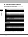
Command Descriptions ..........................................................51
Shell Console Commands................................................................................ 52
4.1.1
4.1.2
4.1.3
4.1.4
4.1.5
4.1.6
4.1.7
4.1.8
4.1.9
4.1.10
viii
Basic Operations .....................................................................13
User Account Settings ...................................................................................... 28
Terminal Emulator ............................................................................................ 29
Ether-Direct Connection ................................................................................... 32
COM Direct Connection ................................................................................... 34
Dual Connection Mode..................................................................................... 36
Setting the IP Address with DHCP ................................................................... 38
Settings via the Menu....................................................................................... 39
SNMP Functions .............................................................................................. 40
Logging Functions ............................................................................................ 42
CF Management of Environment Settings ....................................................... 43
Encrypting/Decrypting a CF Card..................................................................... 44
FTP/SFTP Connection ..................................................................................... 47
CF Boot Mode .................................................................................................. 49
Chapter 4 4.1.
Preparations..............................................................................................................8
Target Device Connection.........................................................................................9
Local Console Connection ......................................................................................10
Network Connection................................................................................................ 11
Basic Operation Flow ....................................................................................... 14
DIP Switch Settings .......................................................................................... 16
Emulator Application Settings........................................................................... 16
Starting the Product.......................................................................................... 17
Login via the Local Console ............................................................................. 18
Preparing the CF Card ..................................................................................... 19
Setting the IP Address ...................................................................................... 21
Setting the Target Port...................................................................................... 22
Connecting from a Remote Terminal ................................................................ 23
Controlling Target Devices via a Terminal Emulator ......................................... 25
Product Logout and Exit ................................................................................... 26
Chapter 3 3.1.
3.2.
3.3.
3.4.
3.5.
3.6.
3.7.
3.8.
3.9.
3.10.
3.11.
3.12.
3.13.
Rack Mount ...............................................................................................................6
Cable Connection............................................................................................... 7
1.3.1
1.3.2
1.3.3
1.3.4
2.1.
2.2.
2.3.
2.4.
2.5.
2.6.
2.7.
2.8.
2.9.
2.10.
2.11.
Front..........................................................................................................................2
Rear ..........................................................................................................................4
Placement .......................................................................................................... 6
1.2.1
1.3.
Setup.......................................................................................... 1
shutdown Command ...............................................................................................53
reboot Command ....................................................................................................54
logout Command.....................................................................................................55
network Command..................................................................................................56
hostname Command...............................................................................................57
ping Command........................................................................................................58
snmp Command......................................................................................................60
time Command........................................................................................................61
timezone Command................................................................................................62
ntp Command..........................................................................................................63
SERVIS IP-Serial
1p Converter
User's Guide
4.1.11
4.1.12
4.1.13
4.1.14
4.1.15
4.1.16
4.1.17
4.1.18
4.1.19
4.1.20
4.1.21
4.1.22
4.1.23
4.1.24
4.1.25
4.1.26
4.1.27
4.1.28
4.1.29
4.1.30
4.1.31
4.1.32
4.1.33
4.1.34
4.1.35
userlist Command ...................................................................................................64
useradd Command .................................................................................................65
userdel Command...................................................................................................66
userkill Command ...................................................................................................67
passwd Command ..................................................................................................68
userreject Command...............................................................................................69
port Command ........................................................................................................70
version Command ...................................................................................................72
menu Command......................................................................................................73
redirect Command ..................................................................................................74
vt100 Command......................................................................................................75
terminal Command..................................................................................................76
fmount Command ...................................................................................................77
readflash Command................................................................................................78
writeflash Command ...............................................................................................79
display Command ...................................................................................................80
delete Command.....................................................................................................82
copy Command .......................................................................................................83
encrypt Command...................................................................................................85
decrypt Command...................................................................................................86
import Command.....................................................................................................87
export Command.....................................................................................................89
change Command...................................................................................................91
changekey Command .............................................................................................92
cfformat Command..................................................................................................93
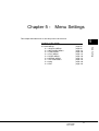
Chapter 5 5.1.
Menu Settings ..........................................................................95
MAIN MENU..................................................................................................... 96
5.1.1
SWITCH MENU ......................................................................................................98
5.1.1.1
5.1.1.2
5.1.1.3
5.1.1.4
5.1.2
shutdown..........................................................................................................................98
reboot ...............................................................................................................................99
logout .............................................................................................................................100
return to MAIN MENU ....................................................................................................100
NETWORK MENU ................................................................................................101
5.1.2.1
5.1.2.2
5.1.2.3
5.1.2.4
5.1.2.5
5.1.2.6
5.1.2.7
5.1.3
set host name.................................................................................................................102
set ip address.................................................................................................................103
set subnet mask .............................................................................................................104
set default gateway ........................................................................................................105
set snmp.........................................................................................................................106
save (NETWORK MENU) ..............................................................................................107
return to MAIN MENU ....................................................................................................107
TIME MENU ..........................................................................................................108
5.1.3.1
5.1.3.2
5.1.3.3
5.1.3.4
5.1.3.5
5.1.3.6
5.1.4
display time ....................................................................................................................109
set time...........................................................................................................................110
set timezone................................................................................................................... 111
set ntp server .................................................................................................................112
save (TIME MENU) ........................................................................................................113
return to MAIN MENU ....................................................................................................113
FILE MENU ...........................................................................................................114
5.1.4.1
5.1.4.2
5.1.4.3
5.1.4.4
5.1.4.5
5.1.4.6
5.1.4.7
5.1.4.8
5.1.4.9
5.1.4.10
5.1.4.11
5.1.4.12
5.1.4.13
display - list ....................................................................................................................115
display - log file ..............................................................................................................116
display - syslog file .........................................................................................................117
delete - log .....................................................................................................................118
delete - conf ...................................................................................................................119
copy - log........................................................................................................................120
copy - conf......................................................................................................................121
copy - syslog ..................................................................................................................122
encrypt - log ...................................................................................................................123
encrypt – conf.................................................................................................................124
decrypt - log ...................................................................................................................125
decrypt - conf .................................................................................................................126
import .............................................................................................................................127
SERVIS IP-Serial
1p Converter
User's Guide
ix
5.1.4.14
5.1.4.15
5.1.4.16
5.1.5
USER MENU.........................................................................................................130
5.1.5.1
5.1.5.2
5.1.5.3
5.1.5.4
5.1.5.5
5.1.5.6
5.1.5.7
5.1.6
list...................................................................................................................................131
add .................................................................................................................................132
delete .............................................................................................................................133
kill ...................................................................................................................................134
reject ..............................................................................................................................135
change password ...........................................................................................................136
return to MAIN MENU ....................................................................................................136
SERIAL MENU......................................................................................................137
5.1.6.1
5.1.6.2
5.1.6.3
5.1.6.4
5.1.6.5
5.1.6.6
5.1.7
set target port .................................................................................................................138
set redirect .....................................................................................................................139
set local console.............................................................................................................141
set VT100.......................................................................................................................142
set port number ..............................................................................................................143
return to MAIN MENU ....................................................................................................143
OPTION MENU.....................................................................................................144
5.1.7.1
5.1.7.2
5.1.7.3
5.1.7.4
5.1.7.5
5.1.8
5.1.9
cf format .........................................................................................................................145
change encrypt of log .....................................................................................................146
change encrypt of conf ...................................................................................................147
version............................................................................................................................148
return to MAIN MENU ....................................................................................................148
ping .......................................................................................................................149
exit.........................................................................................................................150
Chapter 6 6.1.
6.2.
6.3.
Specifications ........................................................................151
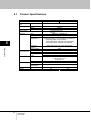
Product Specifications .................................................................................... 152
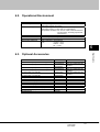
Operational Environment................................................................................ 153
Optional Accessories...................................................................................... 153
Chapter 7 7.1.
7.2.
Troubleshooting.....................................................................155
Definition of Errors.......................................................................................... 156
Self-diagnostic Program ................................................................................. 163
7.2.1
Data R/W test........................................................................................................164
7.2.1.1
7.2.1.1.1
7.2.1.1.2
7.2.1.2
7.2.1.2.1
7.2.1.2.2
7.2.1.3
7.2.1.3.1
7.2.1.3.2
7.2.1.4
7.2.1.4.1
7.2.1.4.2
7.2.1.5
7.2.1.5.1
7.2.1.5.2
7.2.1.6
7.2.1.6.1
7.2.1.6.2
7.2.2
7.2.2.1
7.2.2.2
7.2.2.3
7.2.2.4
7.3.
7.4.
7.5.
x
export .............................................................................................................................128
change ...........................................................................................................................129
return to MAIN MENU ....................................................................................................129
SDRAM test ...................................................................................................................164
data compare test...........................................................................................................164
bus integrity test .............................................................................................................166
FlashROM test ...............................................................................................................167
data compare test...........................................................................................................168
bus integrity test .............................................................................................................169
NIC test ..........................................................................................................................169
data compare test...........................................................................................................170
bus integrity test .............................................................................................................171
RTC test .........................................................................................................................172
data compare test...........................................................................................................172
bus integrity test .............................................................................................................173
Compact Flash test ........................................................................................................174
data compare test...........................................................................................................174
bus integrity test .............................................................................................................175
UART test.......................................................................................................................176
data compare test...........................................................................................................176
bus integrity test .............................................................................................................178
Hardware test........................................................................................................179
DIPSW ...........................................................................................................................179
LED ................................................................................................................................179
CF/Init.............................................................................................................................180
Register Read/Write .......................................................................................................180
Recovery (Returning to Factory Settings) ...................................................... 182
Updating the firmware .................................................................................... 183
Technical Support........................................................................................... 184
SERVIS IP-Serial
1p Converter
User's Guide
1
This chapter covers information required for setting up this product. Please read this
chapter before performing the setup.
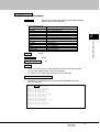
Contents of this chapter
1.1 External Component Names and Functions
page 2
1.1.1 Front
page 2
1.1.2 Rear
page 4
1.2 Placement
page 6
1.2.1 Rack Mount
page 6
1.3 Cable Connection
page 7
1.3.1 Preparations
page 8
1.3.2 Target Device Connection
page 9
1.3.3 Local Console Connection
page 10
1.3.4 Network Connection
page 11
SERVIS IP-Serial
1p Converter
User's Guide
1
Setup
Chapter 1 - Setup
1.1. External Component Names and Functions
1
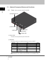
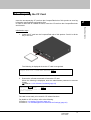
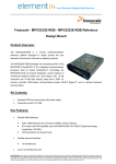
1.1.1
Front (Shown: advanced version FX-3001SRF)
Setup
(6) CompactFlash slot
(1) Power switch
(5) RESET button
(2) DIP switch
(4) Init button
(3) Status LED
(1) Power switch
The switch for turning the device power ON and OFF.
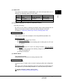
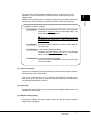
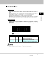
(2) DIP switch
The following settings are available by flipping the switches to ON/OFF.
Dip switch
1: Boot Mode
2: CF boot
3: reserve
4: DHCP
5: Duplex
6: 10/100M
7: Auto Nego
8: reserve
ON
Self-diagnostic mode
CF boot mode
- (reserved)
DHCP or PNP enabled
Ethernet comm. mode: Full
Duplex
Ethernet comm. speed 100M
Auto-negotiation enabled
(DIP switches 5 & 6 disabled
when 7 enabled)
- (reserved)
OFF
Normal startup mode
Normal startup mode
- (reserved)
Internal settings enabled
Ethernet comm. mode: Half
Duplex
Ethernet comm. speed 10M
DIP switches 5 & 6 enabled
- (reserved)
Default
OFF
OFF
OFF
OFF
OFF
OFF
OFF
OFF
After changing the DIP switches, restart the product for the settings to take
effect.
2
SERVIS IP-Serial
1p Converter
User's Guide
(3) Status LED
The status of the device is represented by the color and light status (on or
blinking). The following explains in more detail.
OFF
Gradation
Green
Red
Normal running
Error detected
Booting
At shift to boot from
CF mounting
shutdown
The power is turned off
Recovery in progress (green/red/orange gradation)
Setup
LED
ON
Blinking
Orange
Writing in ROM
CF unmounting
(4) Init button (displayed as CF/Init for advanced version)
Executing a recovery
By turning on the power or pressing the RESET button while pressing the Init
button, the recovery process to restore the default settings is executed.
Refer to 7.3 Recovery (Returning to Factory Settings) (page 182)
Advanced version only
CompactFlash control
This is used to control the insert/eject of the CompactFlash (hereafter, CF).
Mounting a CF card
(1) Insert the CF card into the CF slot.
(2) Press the Init button.
(3) When the LED changes from blinking green to solid green, the CF card
is available.
Ejecting a CF card
(1) Ensuring that the CF card is not being accessed, press the CF/Init
button.
(2) When the LED changes from blinking orange to solid green, the CF
card can be pulled out.
(3) Pull the CF card out.
(5) RESET button
This restarts the device.
Pressing this while the product is running resets the CPU.
Advanced version only
(6) CompactFlash slot
The slot for the CF media, which is used for storing log files and configuration
files.
Only Type-1 CF cards are supported; Type-2 CF cards such as HDD types are
not supported. Any commercially available CF card of any size may be used.
We provide optional CF cards in various sizes.
Refer to 6.3 Optional Accessories (page 153)
SERVIS IP-Serial
1p Converter
User's Guide
1
3
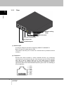
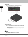
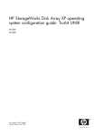
1.1.2
Rear
1
Setup
(5) Adapter holding
clamp
(4) Power jack
(3) Local console port
(2) Target port
(1) Ethernet port
(1) Ethernet port
A socket for Ethernet connection supporting 10BASE-T/100BASE-TX.
Both UTP and STP cables may be used.
This product uses this port to connect to a network and to provide its various
functions.
(2) Target port
Devices with serial consoles or serial controlled devices (e.g. measuring
instruments) are connected to this port. The connector type is an RJ45 modular
jack, and it uses a straight Cat5 UTP or STP cable used for Ethernet
communications. This uses the RS-232C signal and is assigned six types of
signal lines (RxD/TxD/CTS/RTS/DSR/DTR) and a ground wire. The following is
the pin alignment:
1
4
SERVIS IP-Serial
1p Converter
User's Guide
8
1
2
3
4
5
6
7
8
: CTS
: DSR
: RxD
: GND
: GND
: TxD
: DTR
: RTS
Using an RJ45−D-Sub conversion adapter (9-pin or 25-pin), which is sold
separately, it can be modified to a D-Sub connector via this port and a CAT
straight cable.
Therefore, this product can be connected to types that have RJ45 sockets (Sun
products and CISCO products) or types that have a D-Sub (most devices).
Setup
Available conversion adapters
FP-AD009RJ
1
An adapter that establishes an RS-232C cross cable that
combines the target port and a Cat5 straight cable. The
D-Sub side has a 9-pin female.
There may be cross wiring on the side of the device
connected to the target port. If that is the case, use
FP-AD009RJX.
FP-AD025RJ
The same as the FP-AD009J, but with a 25-pin male on
the D-Sub side.
FP-AD009RJX
(one included with this product)
An adapter that establishes an RS-232C cross cable that
combines the local console port and a Cat5 straight
cable. The D-Sub side has a 9-pin female.
FP-AD025RJX
(one included with this product)
The same as the FP-AD009RJX, but with a 25-pin male
on the D-Sub side.
(3) Local console port
This port is connected to a console terminal to perform the boot check, settings,
and shutdown check of the product.
This can be connected to a PC by combining FP-AD009RJ (optional) with a
Cat5 cable. A PC can also be used as a console terminal by executing the
console terminal emulator on the PC.
(4) Power jack
Connects the power adapter. Do not use any power adapter other than the one
included with the product.
(5) Adapter holding clamp
A clamp for holding in the power adapter cable. Use this to prevent the power
adapter from unplugging.
SERVIS IP-Serial
1p Converter
User's Guide
5
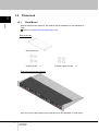
1.2. Placement
1
1.2.1
Rack Mount
Setup
With the optional rack mount kit, the product can be installed to an EIA standard 19"
rack.
Refer to 6.3 Optional Accessories (page 153)
Rack mount kit
Rack mount tray
Unit/tray screw … 4
Tray/rack support screw … 4
Rack mount placement example
Up to four units of this product can be placed into an EIA standard 1U rack mount.
6
SERVIS IP-Serial
1p Converter
User's Guide
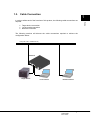
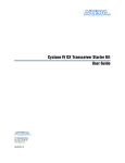
1.3. Cable Connection
1
Target device connection
Local console connection
Network connection
The following sections will discuss the cable connections required to achieve the
configuration below.
LAN (10M, 100M, 1000M Ethernet)
Network
Target device
Local console
Remote terminal
SERVIS IP-Serial
1p Converter
User's Guide
7
Setup
In order to utilize each of the functions of this product, the following cable connections are
required.
1.3.1
1
Preparations
The following are required in order to use this product:
Setup
(1) Serial connection device
A device that has a serial console port.
(2) Conversion adapter (RJ45−D-Sub)
(Optional: FP-AD009RJ, FP-AD025RJ)
This is required to connect to a serial connection device that has a
D-Sub 9-pin or 25-pin port. Using this adapter, it can be modified to a
D-Sub connector via a Cat5 straight cable.
(3) Terminal device (local console)
Use a PC with an RS-232C interface (D-Sub 9-pin).
The PC may run on any OS.
(4) Terminal device (remote terminal)
Use a PC that can connect via Ethernet.
The PC may run on any OS.
(5) Cat5 cable
Use a Cat5 straight cable according to your environment.
Both UTP and STP are supported. The length must be within 20m.
(6) Switching hub
This is required when connecting this product to a terminal device via
Ethernet.
(7) CF card adapter
In order for the above terminal device to read/write data from/to the CF
card included with this product, a separate CF card adapter is required.
(8) Software
Install text editors and/or emulator applications (e.g. TeraTerm) that
meet the needs of your environment.
8
SERVIS IP-Serial
1p Converter
User's Guide
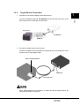
1.3.2
1.
Target Device Connection
1
Connect the conversion adapter to the target device.
Target device
FP-AD009RJ
COM port
2.
Connect the target device to this product.
Connect the adapter just connected to the target device to the target port of this
product using a Cat5 straight cable.
Rear of the target device
Target port
Cat5 straight cable
When attaching/removing connectors or cables to/from the target device, be
sure that this product is turned off.
SERVIS IP-Serial
1p Converter
User's Guide
9
Setup
Connect the adapter (optional: FP-AD009RJ) to the RS-232C connector of the
device that is to be connected to this product.
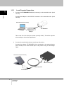
1.3.3
1
1.
Local Console Connection
Connect the FP-AD009RJX adapter (accessory) to the terminal device (local
console).
Setup
Connect the adapter to the RS-232C connector of the terminal device (local
console).
Terminal device (local console)
FP-AD009RJX
COM port
Take a note of the PC serial port number (normally COM1). This will be required
when setting up the emulator application.
2.
Connect the terminal device (local console) to this product.
Connect the adapter (FP-AD009RJX) just connected to the terminal device
(local console) to the local console port of this product using a Cat5 straight
cable.
Terminal device (local console)
Local console port
Cat5 straight cable
FP-AD009RJX
10
SERVIS IP-Serial
1p Converter
User's Guide
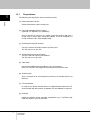
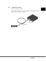
1.3.4
1.
Network Connection
1
Connect the product to a network.
Ethernet port
Cat5 straight cable
Switch hub, etc.
SERVIS IP-Serial
1p Converter
User's Guide
11
Setup
Using a Cat5 straight cable, connect the Ethernet port of this product to a hub or
Ethernet switch. No cables are included.
1
MEMO
Setup
12
SERVIS IP-Serial
1p Converter
User's Guide
Chapter 2 - Basic Operations
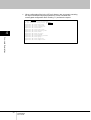
Contents of this chapter
2.1 Basic Operation Flow
page 14
2.2 DIP Switch Settings
page 16
2.3 Emulator Application Settings
page 16
2.4 Starting the Product
page 17
2.5 Login via the Local Console
page 18
2.6 Preparing the CF Card
page 19
2.7 Setting the IP Address
page 21
2.8 Setting the Target Port
page 22
2.9 Connecting from a Remote Terminal
page 23
2.10 Controlling Target Devices via a Terminal Emulator
page 25
2.11 Product Logout and Exit
page 26
SERVIS IP-Serial
1p Converter
User's Guide
13
Basic Operations
This chapter describes the procedures and steps for basic operations using this
product to control serial console devices from a remote terminal.
2
2.1. Basic Operation Flow
This section shows the basic steps for using this product to operate a device connected
to the serial port from a remote terminal.
2
Basic Operations
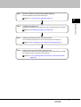
Step 1
Connect this product.
Connect this product to a network, target device, and terminal device
(local console).
Refer to 1.3 Cable Connection (page 7)
Step2
Set the DIP switches.
Set the front DIP switches according to the environment where the product is
to be used.
Refer to 2.2 DIP Switch Settings (page 16)
Step3
Start/configure the emulator application.
Configure the communication software of the local console according to
the interface specifications of this product.
Refer to 2.3 Emulator Application Settings (page 16)
Step4
Start up this product.
Turn on the power switch of this product to start it.
Refer to 2.4 Starting the Product (page 17)
Step5
Log in to this product from the local console.
Enter the "User Account" and "Password" to log in to this product. By default,
there is an administrator account "admin" with the password of "admin".
Refer to 2.5 Login via the Local Console (page 18)
Advanced version only
Step6 Insert the CF card for saving log information.
Insert the CF card, which came with this product, into the CompactFlash slot,
and then prepare it to be used by executing the cfformat command.
Refer to 2.6 Preparing the CF Card (page 19)
14
SERVIS IP-Serial
1p Converter
User's Guide
Step7
Set the IP address of this product (default settings).
Set the IP address of this product and restart it.
Refer to 2.7 Setting the IP Address (page 21)
Basic Operations
Step8
2
Configure the target port.
Configure the target port of this product according to the serial device connected
to it.
Refer to 2.8 Setting the Target Port (page 22)
Step9
Connect to this product from a remote terminal.
From a terminal on the network, connect to this product and configure it.
Refer to 2.9 Connecting from a Remote Terminal (page 23)
Step10 Control the device connected to the target port.
Start the terminal emulator (control application) from the shell console to monitor
and control the device connected to the target port.
Refer to 2.10 Controlling Target Devices via a Terminal Emulator
(page 25)
SERVIS IP-Serial
1p Converter
User's Guide
15
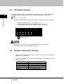
2.2. DIP Switch Settings
Set the DIP switches in the front of the product according to your network environment,
IP address setting method (manual/DHCP), and startup operation (internal flash
ROM/CF).
Refer to 1.1.1 Front (page 2)
2
Basic Operations
The following explanation uses the product setting scenario below as an example.
Manual IP address setting → DIP switch 4 OFF
Communication mode: Auto-negotiation → DIP switch 7 ON
Normal startup with only IPv4 → DIP switches 1, 2, 8 OFF
1
2
3
4
5
6
7
8
On
indicates a switch.
After changing the DIP switches, press the RESET button of the product.
Rebooting is required in order to apply the settings.
2.3. Emulator Application Settings
1.
Power on the terminal device (local console), and then start the emulator
application (e.g. TeraTerm).
2.
Configure the parameters of the emulator application. The following shows the
default parameters:
Protocol
Baud rate
Data length
Parity
Stop bit
Flow control
Emulation
16
SERVIS IP-Serial
1p Converter
User's Guide
Value
115200 bps
8 bits
None
1 bit
None
VT100 compatible terminal
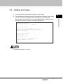
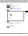
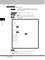
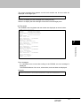
2.4. Starting the Product
Turn on the power switch located on the front of the product.
2.
This implements the startup sequence and performs a hardware check. Upon
no errors, the system is operational and the "login:" prompt is displayed.
(During startup, the STATUS LED turns from blinking green to blinking orange,
and when the startup is complete, it becomes solid green.)
checking system memories...
................................RAM ok
................................ROM ok
...now system loading...
.
...........................done!
SERVIS IP-Serial 1p Converter/CF (FX-3001SRF)
Copyright (c) 2005-2006 FUJITSU COMPONENT LIMITED
Version 1.00 Build 387
Checking system hardware...
.
Real time clock
: ok
..................
Network controller : ok
...............
Compact Flash slot : 122MB media detected.
8:46AM on Wednesday, 17 May 2006
login:
The startup takes approx. 1 minute.
SERVIS IP-Serial
1p Converter
User's Guide
17
2
Basic Operations
1.
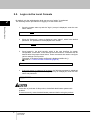
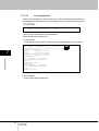
2.5. Login via the Local Console
By default, only the administrative level user account "admin" is registered.
The following are the procedures for logging in as the admin user:
2
Basic Operations
1.
Once the system starts up and the "login:" prompt is displayed, enter the user
name "admin".
login: admin Enter
2.
When the "Password:" prompt is displayed, enter "admin", which is the default
password. The password is not displayed to the screen.
Password:
3.
Enter
Once logged in, the shell console, which is the user interface for system
configuration, is launched. In the shell console environment, commands can be
entered after the prompt shown below. These commands are used to configure
various settings of this product.
The name of the device being configured is displayed within the ().
Refer to 4.1 Shell Console Commands (page 52)
$
4.
If the user name or password is incorrect, the following message is displayed
and you cannot log in. When the "login:" prompt is redisplayed, enter the user
name and password.
Login incorrect
login:
At the time of purchase of this product, the default administrator password is
enabled.
To ensure security, reset the administrator password before using the product.
18
SERVIS IP-Serial
1p Converter
User's Guide
Advanced version only
2.6. Preparing the CF Card
Insert the accompanying CF card into the CompactFlash slot of this product to save log
information and manage configuration files.
In order to utilize the CF related functions, insert the CF card into the CompactFlash slot
and format it.
1.
Insert the CF card into the CompactFlash slot of this product. Push it in all the
way to the end.
The following is displayed when the CF card is recognized.
$
Compact Flash slot : 122MB media detected. Enter
$
2.
Execute the cfformat command to format the CF card.
When the following is displayed, enter the administrator password to execute
format.
Refer to 4.1.35 cfformat Command (page 93)
$ cfformat Enter
administrator password:
Enter
*** Don't eject CF card. ***
Format completed.
$
The card is now ready to be used for CF related functions.
For details on CF functions, refer to the following.
Refer to 3.9 Logging Functions (page 42)
Refer to 3.10 CF Management of Environment Settings (page 43)
SERVIS IP-Serial
1p Converter
User's Guide
19
Basic Operations
Initialization steps
2
Ejecting the CF card
Perform the following steps to eject a CF card that has been recognized.
1.
2
Press the CF/Init button using an object such as a pen.
Basic Operations
CF/Init button
2.
Once the STATUS LED changes from orange to green, the CF card is ready to
be ejected. Press the Eject button and remove the CF card.
Eject button
Inserting a formatted CF card
Perform the following steps to insert and recognize a CF card that has already been
formatted using the cfformat command.
1.
Insert the CF card into the CompactFlash slot, and then press the CF/Init button
using an object such as a pen.
2.
When the STATUS LED blinks green and then becomes solid green, it has
been recognized.
When inserting the CF card, be sure to push it in all the way.
20
SERVIS IP-Serial
1p Converter
User's Guide
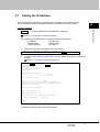
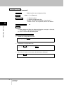
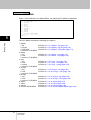
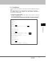
2.7. Setting the IP Address
Part of the initial configuration requires that the IP address of the product be set.
The IP address is set by executing the network command in the shell console.
2
network command
Basic Operations
Syntax
network <ipaddress> <subnetmask> <gateway>
Refer to 4.1.4 network Command (page56)
The following explanation uses the settings below as an example:
IP address:
192.168.0.50
Subnet mask:
255.255.255.0
Default gateway:
192.168.0.1
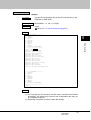
1.
Execute the network command in the shell console.
$ network 192.168.0.50 255.255.255.0 192.168.0.1 Enter
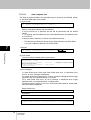
2.
In order for the setting to take effect, use the reboot command to restart the
product.
Refer to 4.1.2 reboot Command (page 54)
$ reboot Enter↵
administrator password:
Enter↵
Shutdown NOW!
$ Wed May 17 18:48:33 GMT 2006
syncing disks... done
rebooting...
checking system memories...
................................RAM ok
................................ROM ok
...now system loading...
.
...........................done!
SERVIS IP-Serial 1p Converter/CF (FX-3001SRF)
Copyright (c) 2005-2006 FUJITSU COMPONENT LIMITED
Version 1.00 Build 387
Checking system hardware...
.
Real time clock
: ok
..................
Network controller : ok
...............
Compact Flash slot : 122MB media detected.
6:49PM on Wednesday, 17 May 2006
login:
The network settings take effect after rebooting.
SERVIS IP-Serial
1p Converter
User's Guide
21
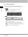
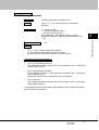
2.8. Setting the Target Port
Configure the target port of this product according to the connected device.
The target port settings are configured using the port command in the shell console.
2
Basic Operations
port command
Syntax
port [-t | -l] [speed] [bit] [parity] [stop] [flow] [xon] [xoff]
Refer to 4.1.17 port Command (page 70)
The following explanation uses the target port settings below as an example:
Protocol
Baud rate
Data length
Parity
Stop bit
Flow control
Value
115200 bps
8 bits
None
1 bit
None
Default settings
9600 bps
8 bits
None
1 bit
None
Procedure
1.
Execute the port command in the shell console.
$ port -t 115200 8 0 1 n Enter
target port setting completed.
$
Once the port command is executed, changes to the port settings immediately take
effect.
This readies the target port for access.
To connect to the target port from a local console, refer to the following.
Refer to 2.10 Controlling Target Devices via a Terminal Emulator (page 25)
For instructions on connecting from a remote terminal over a network, refer to the
following.
Refer to 2.9 Connecting from a Remote Terminal (page 23)
22
SERVIS IP-Serial
1p Converter
User's Guide
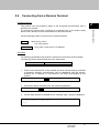
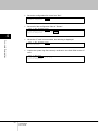
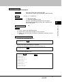
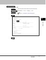
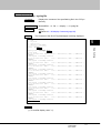
2.9. Connecting from a Remote Terminal
Function overview
Use the following syntax to connect from a network terminal.
Syntax
telnet <host_name>
ssh <host_name>
Parameter(s)
host_name = host name or IP address
Procedure
The following explanation uses a telnet connection to the product as an example.
The following shows the parameter set to the telnet client:
Protocol
Emulation
1.
Value
VT100 compatible terminal
Power on the terminal PC on the network, and then execute the ping command
to determine whether communication can be established with this product.
Assume the IP address of "192.168.0.50" has been pre-assigned to this
product.
C:\temp> ping 192.168.0.50 Enter
2.
Execute the telnet connection from the emulator application.
telnet 192.168.0.50 Enter
3.
Once a telnet session is established, the following "login:" prompt is displayed.
10:54PM on Friday, 12 August 2005
login::
SERVIS IP-Serial
1p Converter
User's Guide
23
2
Basic Operations
This product can be accessed by telnet or ssh encrypted communication from a
terminal on a network.
To configure the product from a terminal on a network, log in to the product using
telnet or ssh, and then execute commands from the shell console.
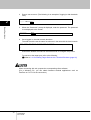
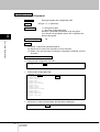
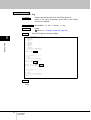
4.
Enter a user account. (The following is an example of logging in with the admin
user.)
11:58AM on Thursday, 25 May 2006
2
login: admin Enter
Basic Operations
5.
When the "Password:" prompt is displayed, enter the password. The password
is not displayed to the screen.
Password:
6.
Enter
Once logged in, the shell console launches.
The shell console uses the same functions as in the case with the local console.
Last login: Thu May 25 10:36:00 2006 on console
$
Execute the desired command in the shell console to configure the product.
To connect to the target port, refer to the following.
Refer to 2.10 Controlling Target Devices via a Terminal Emulator (page 25)
When connecting with ssh, prepare the corresponding client software.
(For a Windows PC, you can obtain freeware terminal applications such as
TeraTerm or PuTTY for the connection.)
24
SERVIS IP-Serial
1p Converter
User's Guide
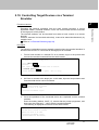
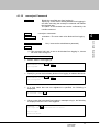
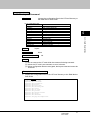
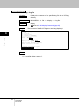
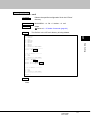
2.10. Controlling Target Devices via a Terminal
Emulator
2
Function overview
Procedure
The following explanation uses an example scenario where the terminal emulator is
launched and a Linux PC connected to the target port is accessed.
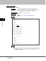
1.
From a local console or a terminal PC on a network, log in to the product and
execute the terminal command from the shell console.
11:58AM on Thursday, 25 May 2006
login: admin Enter↵
Password:
Enter↵
Last login: Thu May 25 10:36:00 2006 on console
$ terminal port1 Enter↵
[launch Terminal-Emulator -- press `^Ec?' to help]
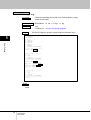
2.
Hit Enter to connect to the target port. In this state, input and output data to and
from the serial device can be monitored.
[launch Terminal-Emulator -- press `^Ec?' to help]
Enter↵
Red Hat Linux release 9 (Shrike)
Kernel 2.4.20-8 on an i686
localhost.localdomain login:
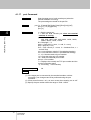
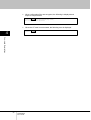
3.
Once the operations of the connected device are completed, exit the terminal
emulator.
Enter the hotkey (default: Ctrl+E, C), ensure that the prompt progresses, and
then enter the command ".", which exits the terminal emulator.
The following is displayed and returns to the shell console.
[launch Terminal-Emulator -- press `^Ec?' to help]
Red Hat Linux release 9 (Shrike)
Kernel 2.4.20-8 on an i686
localhost.localdomain login:
[Terminal-Emulator disconnect]
$
SERVIS IP-Serial
1p Converter
User's Guide
25
Basic Operations
Executing the terminal command from the shell console launches a control
application called a "terminal emulator", which can control serial devices connected
to the target port of this product.
The terminal emulator can be launched from either a local console or a remote
terminal.
However, because it is launched exclusively, it cannot be started simultaneously by
multiple users.
Refer to 3.2 Terminal Emulator (page 29)
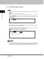
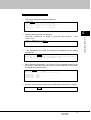
2.11. Product Logout and Exit
Overview
2
Basic Operations
After configuring this product or operating a target device, use the logout command
to log out.
Refer to 4.1.3 logout Command (page 55)
When connecting from a remote terminal with telnet/ssh, logging out automatically
terminates the session.
When connecting from a local console, the following login prompt is displayed again
upon logging out.
$ logout Enter↵
6:51PM on Wednesday, 17 May 2006
login:
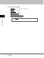
To exit the product, turn off the power switch except when the product is writing to
the ROM or when a recovery is in progress.
Alternatively, execute the shutdown command and check to verify whether the
following is displayed, then turn off the power switch.
Refer to 4.1.1 shutdown Command (page 53)
$ shutdown Enter↵
administrator password:
Enter↵
Shutdown NOW!
$ Wed May 17 18:40:52 GMT 2006
syncing disks... done
The operating system has halted.
Please press any key to reboot.
Turning off the power while a setup command is running in the shell console may
result in unsaved settings. Confirm that the command has been executed and
control has been restored to the shell console before turning off the power switch.
26
SERVIS IP-Serial
1p Converter
User's Guide
Chapter 3 - Function Details
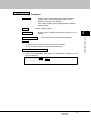
Contents of this chapter
3.1 User Account Settings
page 28
3.2 Terminal Emulator
page 29
3.3 Ether-Direct Connection
page 32
3.4 COM Direct Connection
page 34
3.5 Dual Connection Mode
page 36
3.6 Setting the IP Address with DHCP
page 38
3.7 Settings via the Menu
page 39
3.8 SNMP Functions
page 40
3.9 Logging Functions
page 42
3.10 CF Management of Environment Settings
page 43
3.11 Encrypting/Decrypting a CF Card
page 44
3.12 FTP/SFTP Connection
page 47
3.13 CF Boot Mode
page 49
SERVIS IP-Serial
1p Converter
User's Guide
27
Function Details
This chapter describes each function of this product. The syntax of each command
explained in this chapter will be discussed in Chapter 4.
3
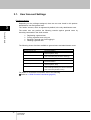
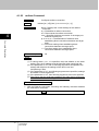
3.1. User Account Settings
Function overview
Depending on the privileges assigned, there are two user levels in this product:
administrator user and general user.
The "admin" account, which is registered by default, is the only administrator user.
3
Function Details
The admin user can perform the following controls against general users by
executing commands in the shell console:
Registering a general user
Forcing a general user to log out
Blocking a general user from logging in
Deleting a general user
The following shows functions available to general users and administrator users:
General user functions
Environment of use
Permitted path
Executable functions
Administrator user functions
Environment of use
Permitted path
Executable functions
- Terminal emulator
- Local console
- Ethernet (telnet, SSH)
- Commands provided by the terminal emulator
- FTP connection (only access to /CF/log/)
- Shell console environment
- Terminal emulator
- Local console
- Ethernet (telnet, SSH)
- Commands provided in the shell console
- Commands provided by the terminal emulator
- FTP connection (access to /CF/)
For details on executable commands, refer to the following.
Refer to 4.1 Shell Console Commands (page 52)
28
SERVIS IP-Serial
1p Converter
User's Guide
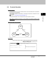
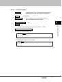
3.2. Terminal Emulator
Function overview
A terminal emulator is the user interface used to control a serial device connected to
the target port of this product.
The terminal emulator is launched by executing the terminal command from the
shell console.
Refer to 4.1.22 terminal Command (page 76)
Also, when a general user logs in to the product, the terminal emulator starts
automatically.
Terminal emulator screen transition
Target
communication
status
Hotkey
input
Waiting for
command
input
Enter key
input
Command
input
Command
result output
status
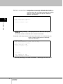
Screen state
Target communication status: A state where data I/O with a connected
device is enabled. The I/O content of the
target port is displayed.
$ terminal port1 Enter↵
[launch Terminal-Emulator -- press `^Ec?' to help]
Red Hat Linux release 9 (Shrike)
Kernel 2.4.20-8 on an i686
Data output from the target device
localhost.localdomain login:
SERVIS IP-Serial
1p Converter
User's Guide
29
Function Details
The terminal emulator can be executed via a local console or network.
3
Waiting for command input: A state where a prompt was displayed after a hotkey
was pressed from the target communication status, the
communication with the target was suspended, and the
system is currently waiting for input of a terminal
emulator command key.
$ terminal port1
[launch Terminal-Emulator -- press `^Ec?' to help]
3
Red Hat Linux release 9 (Shrike)
Kernel 2.4.20-8 on an i686
localhost.localdomain login:
Function Details
[
When pressing a hotkey, "[" is displayed below the terminal, and a prompt is
displayed.
A terminal emulator command can be entered in this state.
Command result output status: A state where the results of a command key are
output. Pressing Enter returns to the target
communication status.
$ terminal port1
[launch Terminal-Emulator -- press `^Ec?' to help]
Red Hat Linux release 9 (Shrike)
Kernel 2.4.20-8 on an i686
localhost.localdomain login:
[port status]
local: 115200 np 8 1 none
port1: 115200 np 8 1 none
-- press Enter key to continue --
Entering the Display Port Status command "x" will display the above results.
30
SERVIS IP-Serial
1p Converter
User's Guide
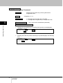
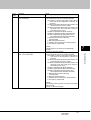
Hotkey functions
Entering a hotkey combination causes, the terminal emulator to suspend
communication via target port and enables the execution of a terminal emulator
command.
Default hotkey setting:
Ctrl + E, C
3
Terminal emulator commands
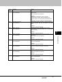
The following is a list of command keys:
Command key
.
e
s
b
o
x
z
?
Process
Exits the terminal emulator. Returns to the shell console.
Modifies hotkey setting (two alphanumeric chars).
Restores the default setting after exiting the terminal
emulator.
Modifies line count of the terminal (default: 24).
Sends break code to target device.
Redisplays the log file.
Displays port settings.
Temporarily goes to shell console.
To return to the terminal emulator from the shell console,
execute the "fg" command from the shell prompt.
Displays Help on terminal emulator commands.
Changes to the hotkey settings are not saved. The next time the terminal
emulator is started, the default settings are restored.
When temporarily going to the shell from the terminal emulator with the
"z" command, execute the "fg" command from the shell prompt to return
to the terminal emulator.
SERVIS IP-Serial
1p Converter
User's Guide
31
Function Details
Terminal emulator commands are executed by entering one of the following
command keys after pressing a hotkey combination to suspend communication with
the target.
Pressing the Enter key after the command is completed restores the target
communication status.
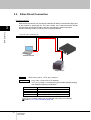
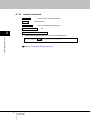
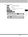
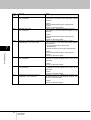
3.3. Ether-Direct Connection
Function overview
Ether-direct connection is a connection method that directly accesses the target port
of the product by specifying the TCP port number via a network terminal without
going through a terminal emulator, and then executing the telnet connection.
Use the following syntax to connect from a network terminal.
3
Function Details
LAN (10M, 100M, 1000M Ethernet)
#3000x
Remote terminal
Target device
Syntax
telnet <host_name> <TCP_port_number>
Parameter(s)
host_name = host name or IP address
TCP_port_number = corresponding port number (default setting)
that supports following connections
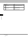
TCP port number
30003
30002
30001
30000
Connection
Read/write port for the target port
Write-only port for the target port
Read-only port (1) for the target port
Read-only port (2) for the target port
The TCP port number setting can be changed using the port command.
Refer to 4.1.17 port Command (page 70)
32
SERVIS IP-Serial
1p Converter
User's Guide
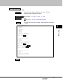
Procedure
The following explanation uses an example scenario when accessing the target port
(read/write) with a telnet connection.
1.
Power on the terminal PC on the network, and then execute the telnet
connection from the emulator application. (Assume the IP address of
"192.168.0.50" has been pre-assigned to this product.) Specify port number
30003 (read/write).
3
C:\temp> telnet 192.168.0.50 30003 Enter
This establishes a connection to the target port. In this state, input and output
data to and from the serial device can be monitored.
3.
After finishing monitoring/configuring the connected device, disconnect the
communication.
When connecting using an emulator application such as TeraTerm, select
"Disconnect" or "Exit" from the drop-down menu.
When connecting via the command line from a UNIX host, etc., enter the telnet
escape code "~]" and type "quit" to exit.
If a connection cannot be established, check the IP address and target port
settings of this product.
Since a connection to the above TCP ports (30003, 30002, 30001, and 30000)
is exclusive, simultaneous instances cannot exist.
Connection/disconnection information of Ether-direct is stored in the clog
(connection log) file.
During an Ether-direct connection, target port logs are not stored.
SERVIS IP-Serial
1p Converter
User's Guide
33
Function Details
2.
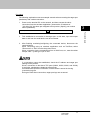
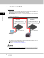
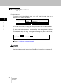
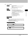
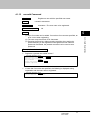
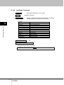
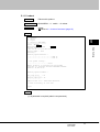
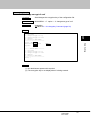
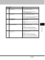
3.4. COM Direct Connection
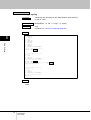
Function overview
COM direct connection is a connection method that directly controls the target port
from a local console without going through a terminal emulator.
You can log in from a remote terminal and execute the redirect command to
establish a COM direct connection.
Refer to 4.1.20 redirect Command (page 74)
3
Function Details
LAN (10M, 100M, 1000M Ethernet)
Remote terminal
Local console
Target device
First ensure that the serial port settings of the target port and local port match when
establishing a COM direct connection.
Proper communication cannot be established if the serial port settings do not match.
34
SERVIS IP-Serial
1p Converter
User's Guide
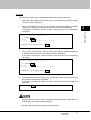
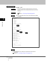
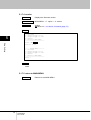
Procedure
1.
Log in to the product from a terminal PC on a network, and then match the
settings of the target port and local port.
2.
Execute the redirect command.
$ redirect on com Enter
$
The connection to the target device can be verified when connected to the local
console. (The following is what is displayed when connecting a Linux PC to the
target.)
Red Hat Linux release 9 (Shrike)
Kernel 2.4.20-8 on an i686
localhost.localdomain login:
4.
To disconnect a COM direct connection, log in to the product from a terminal PC
on the network, and then execute the following command.
$ redirect off Enter
$
5.
The COM direct is disconnected at the local console, and the following login
screen is displayed.
Red Hat Linux release 9 (Shrike)
Kernel 2.4.20-8 on an i686
localhost.localdomain login:
5:24PM on Wednesday, 09 November 2005
login:
During a COM direct connection, other connections (terminal emulator or
Ether-direct) cannot access the target port.
During a COM direct connection, target port logs are stored.
SERVIS IP-Serial
1p Converter
User's Guide
35
Function Details
3.
3
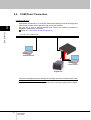
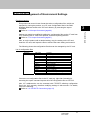
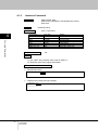
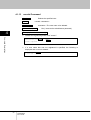
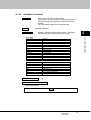
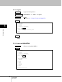
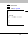
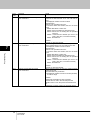
3.5. Dual Connection Mode
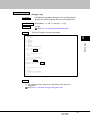
Function overview
Dual connection is a connection mode where two products are connected via the
Internet and two target ports are simultaneously controlled.
SSL encrypted security is achieved for the network between the client device and
the server device.
3
Function Details
LAN (10M, 100M, 1000M Ethernet)
Client device
redirect on ip 192.168.0.175 -s
Specify the destination (server)
Server device
redirect on ip 192.168.0.178 -c
Specify the destination (client)
Device B: 192.168.0.175
Device A: 192.168.0.178
Client
Target device
You can log in from a remote terminal and execute the redirect command from the
shell console to establish a dual connection.
Refer to 4.1.20 redirect Command (page 74)
First ensure that the serial port settings of the client device and server device
match when establishing a dual connection.
Proper communication cannot be established if the serial port settings do not match.
36
SERVIS IP-Serial
1p Converter
User's Guide
Procedure
The following explains how to establish and disconnect a dual connection.
1.
Match the serial settings of the target ports of the client device (Device A) and
the server device (Device B).
2.
Log in to the client device (Device A), and then execute the redirect command
using the IP address or server name of the dual connection destination.
(It will take a moment for control to return to the shell once the command is
executed.)
Function Details
2:26PM on Friday, 24 February 2006
login: admin Enter↵
Password:
Enter↵
Last login: Fri Feb 24 14:28:34 2006 on console
$ redirect on ip 192.168.0.175 -s Enter↵
$
3.
Log in to the server device, and then execute the redirect command using the
IP address and client name of the dual connection destination.
(It will take a moment for control to return to the shell once the command is
executed.)
2:26PM on Friday, 24 February 2006
login: admin Enter↵
Password:
Enter↵
Last login: Fri Feb 24 14:28:34 2006 on console
$ redirect on ip 192.168.0.178 -c Enter↵
$
4.
3
To disconnect a dual connection, log in to the product from a local console, and
then execute the following command.
(It will take a moment for control to return to the shell once the command is
executed.)
$ redirect off Enter
$
During a dual connection, other connections (terminal emulator, Ether-direct, or
COM direct) cannot access the target port.
During a dual connection, target port logs are stored.
SERVIS IP-Serial
1p Converter
User's Guide
37
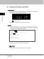
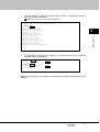
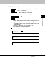
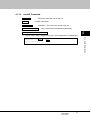
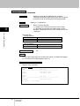
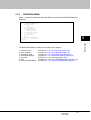
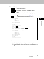
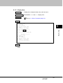
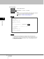
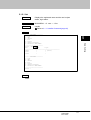
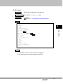
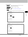
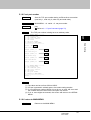
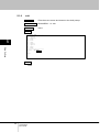
3.6. Setting the IP Address with DHCP
Function overview
When turning on this product with DIP switch 4 ON, a DHCP server on the network
can automatically set the IP address of the product.
3
1
2
3
4
5
6
7
8
Function Details
On
indicates a switch.
To view the auto-set IP address, perform the following steps.
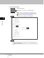
Procedure
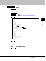
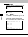
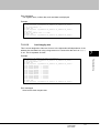
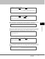
1.
From a local console, log in to the product as the administrator user "admin",
and execute the network command without any parameters to display the
following IP address when DHCP is enabled.
login: admin Enter↵
Password:
Enter↵
Last login: Fri Feb 24 14:28:34 2006 on console
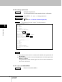
$ network Enter↵
<ip address> 192.168.0.169
<subnet mask> 255.255.255.0
<default gateway> 192.168.0.1
<DHCP = YES>
ip address 192.168.0.5
subnet mask 255.255.255.0
default gateway 192.168.0.1
$
For the above, the setting of 192.168.0.5 can be verified.
Note that the startup time is longer when DHCP is enabled.
38
SERVIS IP-Serial
1p Converter
User's Guide
3.7. Settings via the Menu
Function overview
The settings of this product can be configured by two interfaces: via the command
line from the shell console environment and via a menu screen.
$ menu Enter
== MAIN MENU ========
1. switch
2. network
3. time
4. file
5. user
6. serial
7. option
8. ping
0. exit
=====================
select >
Selecting a setting item from this menu configures the same settings as command
line executions in an easier manner.
For details on the menu, refer to the following.
Refer to Chapter 5 - Menu Settings (page 95)
SERVIS IP-Serial
1p Converter
User's Guide
39
3
Function Details
When logged in to the product, initially the command line interface is displayed;
however, the menu screen can be displayed by executing the menu command.
Refer to 4.1.19 menu Command (page 73)
3.8. SNMP Functions
Function overview
This product supports SNMP; therefore, snmpd can be turned on/off by executing
the snmp command.
Refer to 4.1.7 snmp Command (page 60)
3
Custom settings can be used by importing the /CF/conf/snmpd.conf file modified
according to the environment and purpose of use.
Function Details
In default setting all users are allowed to gain access via a read community called
"public".
Setting procedure (example)
The following explanation uses an example scenario when allowing access by a
network user using a read community called "public".
1.
Insert the CF card and press the CF/Init button to ready the CF card. Execute
the export command to export the current snmpd.conf settings to the /CF/conf
directory.
Refer to 4.1.32 export Command (page 89)
$ export
exported
exported
exported
exported
exported
exported
exported
exported
exported
exported
exported
exported
exported
$
2.
Enter
/CF/conf/ntp.conf.
/CF/conf/localtime.
/CF/conf/portmng.cf.
/CF/conf/hosts.
/CF/conf/port.conf.
/CF/conf/ifconfig.sm0.
/CF/conf/users.
/CF/conf/rc.conf.
/CF/conf/passwd.
/CF/conf/master.passwd.
/CF/conf/group.
/CF/conf/services.
/CF/conf/snmpd.conf.
Eject the CF card, and edit the /CF/conf/snmpd.conf file.
* In FTP connection mode, you can "get" the above file and then "put" the edited file.
Refer to 3.12 FTP/SFTP Connection (page 47)
40
SERVIS IP-Serial
1p Converter
User's Guide
3.
Inert the edited CF, press the CF/Init button to have it recognized, and then
execute the import command.
Refer to 4.1.31 import Command (page 87)
Compact Flash slot : 122MB media detected.
Enter
/etc/ntp.conf.
/etc/localtime.
/etc/portmng.cf.
/etc/hosts.
/etc/port.conf.
/etc/ifconfig.sm0.
/etc/users.
/etc/rc.conf.
/etc/passwd.
/etc/master.passwd.
/etc/group.
/etc/services.
/usr/pkg/etc/snmpd.conf.
3
Function Details
$ import
imported
imported
imported
imported
imported
imported
imported
imported
imported
imported
imported
imported
imported
$
4.
Turn snmpd off, and then turn it back on. The product will now run with the
modified snmpd.conf settings.
$ snmp off Enter
administrator password:
snmp setting off.
$ snmp on Enter
administrator password:
snmp setting on.
$
Enter
Enter
With the above steps, the snmpd.conf contents are modified and reflected to the
product.
SERVIS IP-Serial
1p Converter
User's Guide
41
Advanced version only
3.9. Logging Functions
Function overview
The product can log the following data, and if a CF card is inserted, logs can be
stored to the CF card in text format.
3
Save directory
/CF/log
Function Details
/CF/sys
File name
port1
portmng
messages
Content
Target port I/O log
Operation log
syslog
If a CF card is mounted, the target port I/O log is stored to the CF card in real-time.
For other logs (i.e. clog, portmng, messages files), data accumulated to the flash
ROM are saved to the CF card once every hour (at 00 minutes).
To immediately dump the clog, portmng, and messages log files to the CF card,
execute the copy command (-s parameter).
$ copy -s all Enter
Do you copy all file? (y or n) y Enter
copy file completed.
$
Refer to 4.1.28 copy Command (page83)
During an Ether-direct connection, target port logs are not stored.
Connection/disconnection information of Ether-direct is stored in the messages file.
42
SERVIS IP-Serial
1p Converter
User's Guide
Advanced version only
3.10. CF Management of Environment Settings
Function overview
This product can record in text format the various configuration files, which are
required for running the product, to a CF card. Configuration files in the RAM
disk/flash ROM are saved to the /CF/conf directory by executing the export
command.
Refer to 4.1.32 export Command (page 89)
3
Also, to run the product with a desired setting, copy the setting on the CF card,
insert the CF card, and import the files to achieve the same setting environment.
The following shows the configuration files that can be managed by the CF card.
List of configuration files
Directory
/CF/conf/
File name
ntp.conf
localtime
portmng.cf
hosts
port.conf
ifconfig.sm0
users
rc.conf
passwd
master.passwd
group
services
snmpd.conf
Content
NTP config file
Time zone symbolic file
Configuration definition file
Host name definition file
Serial port config file
Network card config file
User config file
Network config file
Password file
Password master file
Group config file
Network service/port config file
Snmpd config file
If there are no configuration files in the CF card (e.g. right after formatting it),
executing the export command exports all of the configuration files to /CF/conf.
Also, /CF subdirectories can be accessed with FTP/SFTP, allowing configuration
files to be "put" remotely, therefore modifying settings in that manner. For details,
refer to the following.
Refer to 3.12 FTP/SFTP Connection (page 47)
SERVIS IP-Serial
1p Converter
User's Guide
43
Function Details
Settings can easily be modified by editing the configuration files on the CF card from
a PC, inserting the CF card to the product, and then importing the files.
Refer to 4.1.31 import Command (page 87)
Advanced version only
3.11. Encrypting/Decrypting a CF Card
Function overview
This product can encrypt and decrypt configuration files and log files on the CF card.
Item
Command
3
Overview
- Encryption
encrypt command
Function Details
- Decryption
decrypt command
Encryption key
* To execute the command, an encryption key is required.
- Encryption key for configuration files
Create/modify with the changekey command (parameter: -c)
- Encryption key for log files
Create/modify with the changekey command (parameter: -l)
File for encryption
- Log files under the /CF/log directory
port1: Target port I/O log
portmng: Operation log
clog: Ether-direct conn/disconn log
- Configuration files under the /CF/conf directory
ntp.conf, localtime, portmng.cf, hosts, port.conf,
ifconfig.sm0, users, rc.conf, passwd, master.passwd,
group, services, snmpd.conf
Encryption algorithm
* Encryption/decryption can be performed on individual files.
- Common key cryptography, AES (256 bits)
When encrypting, an encryption key is required. Execute the changekey command
to set the encryption key.
44
SERVIS IP-Serial
1p Converter
User's Guide
Encryption procedure
The following explanation uses an example scenario where the configuration files
under the /CF/conf directory are encrypted.
1.
When encrypting, an encryption key must be set. Execute the changekey
command to create/modify the encryption key.
Refer to 4.1.34 changekey Command (page 92)
2.
3
Enter
Function Details
$ changekey -c Enter
administrator password:
keycode:
Enter
$
Execute the encrypt command to perform the encryption.
Refer to 4.1.29 encrypt Command (page 85)
$ encrypt -c all Enter
Do you encode all file? (y or n) y Enter
encoded ntp.conf.
encoded portmng.cf.
encoded hosts.
encoded port.conf.
encoded ifconfig.sm0.
encoded users.
encoded rc.conf.
encoded passwd.
encoded master.passwd.
encoded group.
encoded services.
encoded snmpd.conf.
encoded localtime.
$
The configuration files under the /CF/conf directory are encrypted as shown below.
・ョ」ィ・。、・イ」ッ、・ゥョヲ蛛・'・ o q'O・捉{+ニキ㌘信ラ& K
・ B+=Hz ミユ・・3I{㌘ヘ。4 ゥ p ャ! !`v テ NE・ミケリ a キァ\]・V ミ e ヒトサ< V キ 8」 "・マ軽穽メヨ V ㌘・
^Zh=ケ G 歯 Z<AVW イオ\+;6 ㌘ v ゥ糧㌘メ弃㌘@G コ・ヒヲ・J 妓 B、E 典 X@i ヤ㌘ L ヘ・鱶贏㌘ナ㌘・㌘・
Hiy 祀 0 ヒ B>y ヌヘ q・be
ハイ_]u キ T ク R 晟ケチ 8・ラ彁=M チ i 靦・TL トキ tC 逕ヒ ・゚
di コ x・さ X ㌘。a リ^燧(8†夬ト&K
チ
停
AZk\
ニ
~S
摧 U 蛹|ワ p 拊 4*リ K| ・8 V!・ャ&Kh
俿 6l 吊{・セ b ヒ *室 6 ゚ T ホネフュ簗・
When configuration files are encrypted, the import command cannot be executed.
When configuration files are encrypted, executing the export command will prompt
whether or not to overwrite with unencrypted configuration files. Entering "Y"
performs the export.
SERVIS IP-Serial
1p Converter
User's Guide
45
Decryption procedure
The following explanation uses an example scenario where the encrypted
configuration files under the /CF/conf directory are decrypted.
1.
3
Execute the decrypt command to perform the encryption.
Refer to 4.1.30 decrypt Command (page 86)
Function Details
$ decrypt -c all Enter
Do you decode all file? (y or n) y Enter
decoded ntp.conf.
decoded portmng.cf.
decoded hosts.
decoded port.conf.
decoded ifconfig.sm0.
decoded users.
decoded rc.conf.
decoded passwd.
decoded master.passwd.
decoded group.
decoded services.
decoded snmpd.conf.
decoded localtime.
$
The configuration files under the /CF/conf directory are decrypted.
If the encryption key is modified with the changekey command after an encryption is
performed, files encrypted with the original key cannot be decrypted.
46
SERVIS IP-Serial
1p Converter
User's Guide
Advanced version only
3.12. FTP/SFTP Connection
Function overview
This product can download/upload CF files with FTP/SFTP.
With this functionality, log files can be downloaded or configuration files can be
uploaded to modify settings from a remote location.
The following explanation uses an example scenario where target port log files are
downloaded.
Assume the following are set:
The IP address of the product is "192.168.0.101".
The local host directory is "C:\temp".
Procedure
1.
Turn on a PC with network functions, execute the FTP command and establish
an FTP connection with this product.
C:\temp>ftp 192.168.0.101 Enter
2.
When the following is displayed, log in with the admin user.
Connected to 192.168.0.101
220 STD FTP ready.
User (192.168.0.101:(none)): admin Enter
331
Password:
Enter
3.
Authentication is performed and you are logged in to the product.
230
ftp>
4.
Go to the directory where the files for upload/download are located.
ftp> cd /log Enter
250 CWD command successful.
ftp>
SERVIS IP-Serial
1p Converter
User's Guide
47
Function Details
FTP connections can be performed by admin users or general users.
When logged in as an admin user, the /CF directory is the top directory; everything
under /CF can be accessed.
When logged in as a general user, the /CF/log directory is the top directory; only
/CF/log and subdirectories can be accessed.
3
5.
Execute "get" to download files (product to FTP client); execute "put" to upload
files (FTP client to product). The target I/O log file is downloaded here.
ftp> get port1 Enter
6.
3
The file is transferred.
Function Details
200 PORT command successful.
150 Opening ASCII mode data connection for ’port1’ (3747 bytes).
226 Transfer complete.
ftp: 3862 bytes received in 0.20Seconds 19.02Kbytes/sec.
7.
Disconnect the local host from the FTP server.
ftp> bye Enter
221Data traffic for this session was 3862 bytes in 1 file.
Total traffic for this session was 4279 bytes in 1 transfer.
221 Thank you for using the FTP service on localhost.
48
SERVIS IP-Serial
1p Converter
User's Guide
Advanced version only
3.13. CF Boot Mode
Function overview
In this mode, the file system is loaded, not from the internal flash ROM, but the CF
card.
Selecting boot media
Whether to use CF boot or normal boot is determined by the DIP switch on the front
of the product.
To use CF boot, turn DIP switch 2 on, insert a bootable CF (FFS format) into the CF
slot, and then turn the product on.
1
2
3
4
5
6
7
8
On
indicates a switch.
Operation
Normal startup
(IPv4)
Dip SW 2
OFF
Dip SW 8
OFF
CF boot
ON
-
Detail
Starts the device with kernel on the flash ROM.
Extracts the file system image on the flash ROM to
the RAM.
Uses the IPv4 configuration file.
Uses IPv4 supported configuration files.
Starts the device with kernel on the CF.
Uses the file system on the CF.
* A bootable CF (FFS format) must be inserted.
When booting from the CF card, the CF card cannot be formatted.
SERVIS IP-Serial
1p Converter
User's Guide
49
3
Function Details
By placing the binary, which should be in the internal flash ROM, to the CF card, an
entirely different system can be launched. An environment that executes
auto-processing against the local console or target port is provided.
By executing a perl script, data on each target port can be checked and reported to
the local console, or devices connected to the target ports can be auto-controlled.
MEMO
3
Function Details
50
SERVIS IP-Serial
1p Converter
User's Guide
Chapter 4 - Command
Descriptions
4
Contents of this chapter
4.1 Shell Console Commands
4.1.1 shutdown Command
4.1.2 reboot Command
4.1.3 logout Command
4.1.4 network Command
4.1.5 hostname Command
4.1.6 ping Command
4.1.7 snmp Command
4.1.8 time Command
4.1.9 timezone Command
4.1.10 ntp Command
4.1.11 userlist Command
4.1.12 useradd Command
4.1.13 userdel Command
4.1.14 userkill Command
4.1.15 passwd Command
4.1.16 userreject Command
4.1.17 port Command
4.1.18 version Command
4.1.19 menu Command
4.1.20 redirect Command
4.1.21 vt100 Command
4.1.22 terminal Command
4.1.23 fmount Command
4.1.24 readflash Command
4.1.25 writeflash Command
4.1.26 display Command
4.1.27 delete Command
4.1.28 copy Command
4.1.29 encrypt Command
4.1.30 decrypt Command
4.1.31 import Command
4.1.32 export Command
4.1.33 change Command
4.1.34 changekey Command
4.1.35 cfformat Command
page 52
page 53
page 54
page 55
page 56
page 57
page 58
page 60
page 61
page 62
page 63
page 64
page 65
page 66
page 67
page 68
page 69
page 70
page 72
page 73
page 74
page 75
page 76
page 77
page 78
page 79
page 80
page 82
page 83
page 85
page 86
page 87
page 89
page 91
page 92
page 93
SERVIS IP-Serial
1p Converter
User's Guide
51
Command Descriptions
This chapter describes the syntax of various commands used to control this product.
4.1. Shell Console Commands for admin user
The following is a list of commands that are executable in the shell console environment.
Only admin user can execute the shell console commands.
Command list
4
Command Descriptions
No.
1.
2.
3.
4.
5.
6.
7.
8.
9.
10.
Command
shutdown
reboot
logout
network
hostname
ping
snmp
time
timezone
ntp
11.
12.
13.
14.
15.
16.
17.
18.
19.
20.
21.
22.
23.
24.
25.
userlist
useradd
userdel
userkill
passwd
userreject
port
version
menu
redirect
vt100
terminal
fmount
readflash
writeflash
Function
Shuts down the device
Reboots the device
Logs out
Sets own IP address, netmask, gateway
Sets the host name
Sends ICMP packets to the host
Sets SNMP to ON/OFF
Sets the date and time
Sets the time zone
Sets the NTP (turns on/off the client function, registers
the server)
Displays the registered user list
Registers a user
Deletes a user
Forces a user to log out
Changes the password
Blocks a user from logging in
Configures a port
Displays the firmware version
Displays the menu screen
Configures redirect connection
Configures a VT100
Launches the terminal emulator
Mounts/Unmounts the NFS filesystem
Writes flash ROM files to CF or NFS
Writes CF or NFS files to flash ROM
Note
Password required
Password required
Password required
Password required
Password required
Password required
Password required
Password required
Advanced version only
No.
26.
27.
Command
display
delete
28.
copy
29.
encrypt
30.
decrypt
31.
32.
33.
34.
35.
import
export
change
changekey
cfformat
Function
Lists the log files in the CF card
Deletes the configuration files and log files on
card
Copies the configuration files and log files on
card
Encrypts the configuration files and log files on
card
Decrypts the configuration files and log files on
card
Imports configuration files
Exports configuration files
Changes the CF configuration files
Changes the encryption key
Formats the CF card
Note
the CF
the CF
the CF
the CF
Password required
Password required
Password required
The following sections explain the specifications of each of the above commands.
Parameters in the < > cannot be omitted; [] parameters are optional.
52
SERVIS IP-Serial
1p Converter
User's Guide
4.1.1
shutdown Command
Overview
Syntax
Shuts down the system.
shutdown
Parameter(s)
Password required?
None
Yes (* same as the administrator password)
4
Example (from the local console)
Shuts down this product. (The password is not displayed.)
Command Descriptions
$ shutdown Enter↵
administrator password:
Enter↵
Shutdown NOW!
$ Fri Feb 24 14:32:44 GMT+9 2006
syncing disks... done
The operating system has halted.
Please press any key to reboot.
Pressing any key in the above state reboots.
SERVIS IP-Serial
1p Converter
User's Guide
53
4.1.2
reboot Command
Overview
Syntax
Reboots the system.
reboot
Parameter(s)
Password required?
4
None
Yes (* same as the administrator password)
Example (from the local console)
Reboots this product. (The password is not displayed.)
Command Descriptions
$ reboot Enter↵
administrator password:
Enter↵
Shutdown NOW!
$ Fri Feb 24 14:32:44 GMT+9 2006
syncing disks... done
The operating system has halted.
Please press any key to reboot.
rebooting...
checking system memories...
................................RAM ok
................................ROM ok
...now system loading...
.
...........................done!
SERVIS IP-Serial 1p Converter/CF (FX-3001SRF)
Copyright (c) 2005-2006 FUJITSU COMPONENT LIMITED.
Version 1.00 Build 387
Checking system hardware...
.
Real time clock
: ok
..................
Network controller : ok
...............
Compact Flash slot : 122MB media detected.
2:35PM on Friday, 24 February 2006
login:
54
SERVIS IP-Serial
1p Converter
User's Guide
4.1.3
logout Command
Overview
Syntax
Logs out of the product system and displays the login
prompt.
logout
Parameter(s)
Password required?
None
No
4
Example (from the local console)
Command Descriptions
Logs out of the product system.
$ logout Enter↵
2:36PM on Friday, 24 February 2006
login:
SERVIS IP-Serial
1p Converter
User's Guide
55
4.1.4
network Command
Overview
Syntax
Displays/sets the current network information of product.
network <ipaddress> <subnetmask> <gateway>
network [-I | -m | -g ] [name]
Parameter(s)
4
Command Descriptions
Password required?
None = Displays current network settings.
ipaddress = Specifies the IP address.
subnetmask = Specifies the subnet mask.
gateway = Specifies the default gateway.
-I = Only sets the IP address. Specify the IP addres to
Name.
-m = Only sets the subnet mask. Specify the subnet
mask to Name
-g = Only sets the default gateway. Specify the default
gateway to Name.
No
Notes
(1) Unless the system is restarted, the changes made by the network
command are not reflected.
Example (from the local console)
The following example sets the IP address to "192.168.0.50", the subnet
mask to "255.255.255.0", and the default gateway to "192.168.0.1".
1.
Enter the network command.
$ network 192.168.0.50 255.255.255.0 192.168.0.1 Enter
ip address setting completed.
subnet mask setting completed.
default gateway setting completed.
$
2.
Execute the reboot command to restart the product. Rebooting is required
in order to apply the settings.
Refer to 4.1.2 reboot Command (page 54)
If the Dip switch is set to use a DHCP server and the network command is
executed without any parameters, the IP address, subnet mask, and default
gateway assigned by the DHCP server are also displayed.
56
SERVIS IP-Serial
1p Converter
User's Guide
4.1.5
hostname Command
Overview
Syntax
Displays/sets the current host name.
hostname [name-of-host]
Parameter(s)
Password required?
None = Displays the current host name.
name-of-host = Sets the specified host name.
No
4
Notes
Command Descriptions
(1) The host name has a limit of 63 characters. If it is 64 or more
characters long, only the first 63 are set.
Example (from the local console)
Sets the host name to "LL1".
$ hostname LL1 Enter
host name setting completed.
$
Displays the current host name.
$ hostname Enter
<hostname> LL1
$
SERVIS IP-Serial
1p Converter
User's Guide
57
4.1.6
ping Command
Overview
Syntax
Parameter(s)
4
Command Descriptions
58
SERVIS IP-Serial
1p Converter
User's Guide
Sends an ICMP ECHO_REQUEST packet to a host on
the network.
ping [-dfnoqrvDPQRL] [-c count] [-g gateway] [-I interval]
[-l ifaddr] [-l preload] [-p pattern] [-s packetsize] [-t tos]
[-T ttl] [-w maxwait] <host>
-c count = Stops sending ECHO_RESPONSE packets
after sending out the packet for as many times as
specified by the count parameter (and after waiting for
the specified delay for a response).
-d = Sets the SO_DEBUG option when using socket.
-D = Sets the Don’t Fragment bit of the IP header. This
can be used to limit the MTU of that path.
-f = Flood ping. Sends the output out immediately after a
packet returns or 100 times within a second; the faster
of the two. The "." character is displayed for every
ECHO_REQUEST packet sent, whereas a backspace
is output for every ECHO_REPLY packet received.
Therefore, you can quickly see how many packets
have been lost. Since this puts a heavy load on the
network, use this with caution.
-g gateway = Sends ECHO_REQUEST packets through
the gateway using Loose Source Routing.
-I interval = Sends packets in intervals of the specified
seconds. By default, packets are sent in intervals of 1
second; however, the -f option is an exception where
packets are sent every 0.01 seconds.
-l ifaddr = Sends multicast datagrams to the network
interface specified by the host name or IP address.
-h host = An alternative method of specifying the target
host name for the last argument.
-l preload = Before going into normal operation mode,
this sends a certain number of packets specified by
preload as fast as possible.
-L = Disables loop back for multicast interface
destinations so that the source host cannot receive
ICMP requests.
-n = Only outputs numeric values. This does not look up
the symbol name of the host address.
-o = Exits upon receiving one response packet.
-p pattern = Specifies up to 16 bytes to send out for the
“pad" part of the outgoing packet. This is effective
when diagnosing a data-dependent problem on the
network. For example, "-p ff" fills the packets with 1's.
-P = By default, the data part uses an incremented
sequence of 8-bit integers, but this uses a
pseudo-random sequence for the data part. This is
effective when disabling compression for PPP and
other links.
-q = Controls the output. Other than the few lines content
displayed at startup and finish, nothing is displayed.
-Q = Does not display ICMP responses such as
Password required?
No
Notes
(1) There is no output if there is no response.
Example (from the local console)
Specifies the host and performs a ping.
$ ping 192.168.0.4 Enter
PING 192.168.0.4 (192.168.0.4): 56 data bytes
64 bytes from 192.168.0.4: icmp_seq=0 ttl=128 time=7.621 ms
64 bytes from 192.168.0.4: icmp_seq=1 ttl=128 time=10.415 ms
^C
----192.168.0.4 PING Statistics---2 packets transmitted, 2 packets received, 0.0% packet loss
round-trip min/avg/max/stddev = 7.621/9.018/10.415/1.976 ms
$
SERVIS IP-Serial
1p Converter
User's Guide
59
4
Command Descriptions
"Network Unreachable" for the sent
ECHO_REQUEST.
-R = Records the path. This includes the
RECORD_ROUTE option to the ECHO_REQUEST
packet, and displays the path buffer of the packet that
is returned. Note that due to the size of the IP header,
it can only contain eight paths. Most hosts ignore or
discard this option.
r = Bypasses the normal routing table and directly sends
packets to the host on the network. An error is
returned if the specified host does not exist on the
immediate network. This option is recommended
when there is no path information for a specific
interface and when pinging a local host through that
interface (e.g. when an interface is dropped by
routed(8)).
-s packetsize = Specifies the byte size of the outgoing
data. The default is 56 bytes, and when combined with
the 8-byte ICMP header data, the ICMP data becomes
64 bytes. The max value is 65468 bytes.
-T ttl = This uses the specified time-to-live.
-t tos = This uses the type of service specified in
hexadecimal.
-v = Enables verbose mode. This displays other
information in addition to the ECHO_RESPONSE of
the received ICMP packet.
-w maxwait = Specifies the wait time (seconds) for a
packet response before sending out the next packet.
The default is 10.0.
4.1.7
snmp Command
Overview
Sets SNMP to ON/OFF.
When SNMP is enabled, all users are allowed to gain
access via a read community called "public".
This setting can also be changed by editing the
/CF/conf/snmpd.conf file (Advanced version only).
Syntax
4
snmp [on | off]
Parameter(s)
Command Descriptions
Password required?
None = Displays the current SNMP setting.
on = Enables SNMP.
off = Disables SNMP.
Yes (* same as the administrator password)
Example (from the local console)
Enables SNMP. (The password is not displayed.)
$ snmp on Enter
administrator password:
snmp setting on.
$
Enter
Displays the current SNMP setting.
$ snmp Enter
<snmp> on
$
Disables SNMP. (The password is not displayed.)
$ snmp off Enter
administrator password:
snmp setting off.
$
60
SERVIS IP-Serial
1p Converter
User's Guide
Enter
4.1.8
time Command
Overview
Syntax
Sets the date and time.
Specifying the date/time parameters sets the date/time
settings.
Specifying the time zone parameter displays the
date/time of that time zone.
time [ccyymmddhhmm.ss | zone]
Parameter(s)
No
Notes
(1) Before executing the time command, specify the time zone using the
timezone command. After executing the timezone command, set the
date/time with the time command.
(2) Time adjustments for daylight savings, standard times, leap seconds
and leap years are performed automatically.
Example (from the local console)
Displays the current date/time setting.
$ time 200602241515.00 Enter↵
time setting completed.
$
Displays the current date/time.
$ time Enter↵
Fri Feb 24 15:15:43 2006 GMT+9
$
SERVIS IP-Serial
1p Converter
User's Guide
61
4
Command Descriptions
Password required?
None = Displays the current date and time.
cc = The first two decimal digits (century) of the year.
yy = The second two decimal digits of the year.
If "yy" is specified but "cc" is not, the value of "cc" is 19
for "yy" values between 69 and 99, and "20" for the
other values.
mm = Month (numeric value: 1-12).
dd = Days (numeric value: 1-31).
hh = Hour (numeric value: 0-23).
mm = Minutes (numeric value: 0-59).
.ss = Seconds (numeric value: 0-61).
zone = Time zone name.
4.1.9
timezone Command
Overview
Syntax
Sets the time zone.
Without any parameters, this displays the current
time zone.
timezone [zone]
Parameter(s)
4
zone = Time zone
Command Descriptions
zone setting
JST
PST
MST
CST
EST
UTC
GMT-12 to +12
Password required?
Time zone
Japan
Pacific
Mountain
Central
Eastern
UTC
GMT
Region
Japan
US (Pacific)
US (Mountain)
US (Central)
US (Eastern)
Coordinated universal time
Greenwich mean time
No
Notes
(1) For "GMT" only, the time zone is set at "GMT+0".
(2) Enter the zone using upper case letters.
Example (from the local console)
Sets the time zone.
$ timezone GMT+9 Enter
time setting completed.
$
Displays the current time zone setting.
$ timezone Enter
<timezone> GMT+9
$
62
SERVIS IP-Serial
1p Converter
User's Guide
4.1.10
ntp Command
Overview
Syntax
Sets the start/stop of ntpd and specifies the NTP server.
ntp [-o | -f] [server name]
Parameter(s)
Password required?
None = Displays the current settings.
-o = Starts the ntpd.
-f = Stops the ntpd.
server name = Specifies the NTP sever.
4
No
(1) When executing ntpd, set the date and time in advance using the time
command. When the configured date and time vary greatly from the
time on the time server, the time cannot be obtained.
(2) Rebooting is required in order to apply the settings. Use the reboot
command to restart the system after changing the settings. By default,
ntpd is set to OFF.
(3) If ntpd is not specified, the current ntpd setting is used.
(4) The server name has a limit of 63 characters.
Example (from the local console)
Starts ntpd.
$ ntp -o 192.168.0.100 Enter
ntp setting on.
$
Displays the current NTP setting.
$ ntp Enter↵
<ntp> on
192.168.0.100
$
Stops ntpd.
$ ntp -f Enter
ntp setting off.
$
SERVIS IP-Serial
1p Converter
User's Guide
63
Command Descriptions
Notes
4.1.11
userlist Command
Overview
Syntax
Displays the registered users and the user’s reject
status, login status.
userlist
Parameter(s)
None
Password required?
4
No
Example (from the local console)
Command Descriptions
Displays a list of registered users.
$ userlist Enter↵
user
reject
login
-----------------------------------------------admin
o (shell)
test1
o (terminal)
test2
x
test3
$
The content of the marks is shown as follows.
Item
reject
login
Mark
-
×
-
○ (shell)
○ (terminal)
Content
The user can log in.
The user cannot log in.
The user is not logging in.
The user is logging in.
(The shell console is starting.)
The user is logging in.
(Terminal-Emulator is starting.)
The user's reject setting is executed by the userreject command.
Refer to 4.1.16 userreject Command (page 69)
64
SERVIS IP-Serial
1p Converter
User's Guide
4.1.12
useradd Command
Overview
Syntax
Registers a user with the specified user name.
useradd <username>
Parameter(s)
Password required?
username = The user name to be registered.
No
4
Notes
Example (from the local console)
Registers a general user called "tester1".
$ useradd tester1 Enter
administrator password:
Enter
Changing local password for tester1.
New password:
Enter
Retype new password:
Enter
useradd completed.
$
If more than four users are specified, the following is displayed during
registration and the users are not registered.
$ useradd tester5 Enter
can not add user. entry over.
$
SERVIS IP-Serial
1p Converter
User's Guide
65
Command Descriptions
(1) Up to four users can be added. If more than four users are specified, an
error occurs when registering.
(2) The user name has a limit of 63 characters.
(3) Pressing the Enter key without entering anything when setting the
password during a user registration will register the user without a
password. Afterwards, the passwd command can be used to set a
password.
4.1.13
userdel Command
Overview
Syntax
Deletes the specified user.
userdel <username>
Parameter(s)
username = The user name to be deleted.
Password required?
4
Yes (* same as the administrator password)
Example (from the local console)
Deletes the registered general user "tester1".
Command Descriptions
$ userdel tester1 Enter
administrator password:
userdel completed.
$
Enter
If a user name that was not registered is specified, the following is
displayed and no user is deleted.
$ userdel user1 Enter
No such user `user1'
$
66
SERVIS IP-Serial
1p Converter
User's Guide
4.1.14
userkill Command
Overview
Syntax
Forces the specified user to log out.
userkill <username>
Parameter(s)
Password required?
username = The user to be forced to log out.
Yes (* same as the administrator password)
4
Example (from the local console)
Forces "user1" who is logged in to log out. (The password is not displayed.)
Command Descriptions
$ userkill tester1 Enter
administrator password:
userkill completed.
$
Enter
SERVIS IP-Serial
1p Converter
User's Guide
67
4.1.15
passwd Command
Overview
Syntax
Modifies the password of the specified user.
passwd [username]
Parameter(s)
4
None = Changes the password of the currently logged in
user.
username = Specifies the user name of the password to
be changed.
Password required?
Yes (* same as the user password)
Command Descriptions
Notes
(1) Only the logged in user or admin can change a password.
(2) Pressing the Enter key without entering anything during the "New
password:" prompt does not modify the password.
Example (from the local console)
Changes the password of "tester1" (the password is not displayed).
$ passwd tester1 Enter
Changing local password for tester1.
New password:
Enter
Retype new password:
Enter
$
If a user name that was not registered is specified, the following is
displayed and no password is changed.
$ passwd user1 Enter
not found username
$
68
SERVIS IP-Serial
1p Converter
User's Guide
4.1.16
userreject Command
Overview
Syntax
Blocks the specified user from logging in.
Specifying a user that is already blocked from logging in
and then executing the userreject command will release
the blocked user.
The status of the blocked user can be confirmed by the
userlist command.
userreject <username>
Parameter(s)
Yes (* same as the administrator password)
Notes
(1) This command only sets a user to be blocked from logging in; it does
not force users to log out.
Example (from the local console)
Blocks "tester1" from logging in.
$ userreject tester1 Enter
administrator password:
user rejected.
$
Enter
Specifying a user that is already blocked from logging in releases the block.
$ userreject tester1 Enter
administrator password:
user un-rejected.
$
Enter
If a user name that was not registered is specified, the following is
displayed.
$ userreject user1 Enter
No such user `user1'
$
When a user that is blocked from logging in attempts to log in, the following
is displayed and the user is not logged in.
login: tester1 Enter
Password:
Enter
Last login: Thu Aug 4 09:20:28 2005 on console
Can not login.
Permission denied.
SERVIS IP-Serial
1p Converter
User's Guide
69
4
Command Descriptions
Password required?
username = The user name to be blocked from logging
in.
4.1.17
port Command
Overview
Syntax
4
Sets the target port or local console port (when the
terminal emulator is running).
The port settings are saved to the port file.
port [-t | -l] [speed] [bit] [parity] [stop] [flow] [xon] [xoff]
port [-r1 | -r2 | rw] [port-no]
port [-n]
Parameter(s)
Command Descriptions
Password required?
-t = Sets the target port
-l = Sets the local console port when the terminal
emulator is running
speed = Sets the baud rate
300, 1200, 1800, 2400, 4800, 9600, 14400, 19200,
28800, 38400, 57600, 115200
bit = Bit length 7 - 8
parity = Parity bit (0 = none, 1 = odd, 2 = even)
stop = Stop bit (1 or 2)
flow = Flow control (n = none, h = hardware flow, x =
xon/xoff flow)
xon = xon character code 0x?? (hexadecimal setting)
xoff = xoff character code 0x?? (hexadecimal setting)
-r1, -r2 = Sets the read-only port number
-wo = Sets the write-only port number
-rw = Sets the read/write port number
port-no = Port number
-n = Displays the currently set TCP port number and the
current connecting status
(o: connecting, -: unconnection)
No
Notes
(1) If the target port is connected by the terminal emulator or direct
connection, port changes cannot be performed using the port
command.
(2) If flow control is set to n or h, an error occurs when entering xon or xoff.
(3) Specify the port number within the range of 5000 - 65535.
70
SERVIS IP-Serial
1p Converter
User's Guide
Example (from the local console)
The current serial port settings is displayed.
$ port Enter↵
port name
baud
d p s f xon xoff
-----------------------------------------------Local port
115200 8 0 1 n 0x00 0x00
Target port
115200 8 0 1 n 0x00 0x00
$
$ port –t 115200 8 0 1 n Enter↵
target port setting completed.
$
If the parameters are invalid, the following is displayed and the setting
changes fail.
$ port –t 115200 Enter↵
usage: port [-t|-l] [baudrate] [size] [parity] [stop] [flow] [xon] [xoff]
port [-r1|-r2|-wo|-rw] [port-number] | [-n]
$
When specifying parameter -n, the current TCP port number settings of the
Ether-direct connection and the status of current Ether-Direct connection
are displayed as shown below.
$ port –n Enter↵
Ether-Direct
no.
status
-----------------------------------------------<read only1>
30000
<read only2>
30001
<write only>
30002
<read write>
30003
$
Sets the read-write port number for the Ether-direct connection to "30008".
$ port -rw 30008 Enter
$
SERVIS IP-Serial
1p Converter
User's Guide
71
4
Command Descriptions
Sets the target port with the settings of
baud rate: 115200 bps, bit length: 8, parity bit: none, stop bit: 1, flow
control: none.
4.1.18
version Command
Overview
Syntax
Displays the version number.
version
Parameter(s)
Password required?
4
None
No
Example (from the local console)
Displays the version number.
Command Descriptions
$ version Enter↵
Version 1.00 387
$
72
SERVIS IP-Serial
1p Converter
User's Guide
4.1.19
menu Command
Overview
Syntax
Displays the menu screen.
menu
Parameter(s)
None
Password required?
No
4
Example (from the local console)
Displays the menu screen.
Command Descriptions
$ menu Enter
== MAIN MENU ========
1. switch
2. network
3. time
4. file
5. user
6. serial
7. option
8. ping
0. exit
=====================
select >
For details on settings in the menu screen, refer to the following.
Refer to Chapter 5 - Menu Settings (page 95)
SERVIS IP-Serial
1p Converter
User's Guide
73
4.1.20
redirect Command
Overview
Syntax
Configures redirect connection.
redirect [on | off] [com | ip xx.xx.xx.xx [-s | -c]]
Parameter(s)
4
Command Descriptions
Password required?
None = Displays the current settings of the redirect
connection.
on = Establishes a redirect connection.
off = Disconnects the redirect connection.
com = Specifies the direct connection of the target port
and local console port.
ip xx.xx.xx.xx = The destination IP address when
establishing direct connections between two target
ports.
-s = The server setting when establishing direct
connections between two target ports.
-c = The client setting when establishing direct
connections between two target ports.
No
Notes
(1) If nothing either -s or -c is specified, then this defaults to the client
setting. Also, the IP address must be specified when specifying this.
(2) If the parameter is "on" and no following arguments are specified, the
settings will default to the settings of the /etc/rc.conf and
/etc/portmng.cf files.
(3) If the parameter is "on" and following arguments are specified, settings
are based on those arguments.
(4) If the parameter is "off", then following arguments cannot be specified.
(5) First ensure that the serial port settings of the client device and server
device match when establishing a dual connection.
Example (from the local console)
With an Ethernet connection, executing the following command enables
the COM direct connection.
$ redirect on com Enter
$
74
SERVIS IP-Serial
1p Converter
User's Guide
4.1.21
vt100 Command
Overview
Syntax
Configures the VT100. The specified number of lines
determines where the command line is displayed.
vt100 [line]
Parameter(s)
Password required?
None = Displays the current number of lines.
line = Specifies the number of lines.
4
No
Notes
Command Descriptions
(1) Specify the number of lines within the range of 1 - 9999.
Example (from the local console)
Sets the number of lines to 30.
$ vt100 30 Enter
vt100 line setting completed.
$
Displays the current number of lines.
$ vt100 Enter
<vt100> 30 lines
$
SERVIS IP-Serial
1p Converter
User's Guide
75
4.1.22
terminal Command
Overview
Syntax
Launches the terminal emulator.
terminal port1
Parameter(s)
Password required?
4
port1 = Indicates the target port.
No
Example (from the local console)
Starts the terminal emulator and connects to the target port.
Command Descriptions
$ terminal port1 Enter↵
[launch Terminal-Emulator -- press `^Ec?' to help]
Refer to 3.2 Terminal Emulator (page 29)
76
SERVIS IP-Serial
1p Converter
User's Guide
4.1.23
fmount Command
Overview
Syntax
Mounts or unmounts NFS filesystem.
The mount point is /mnt (fixation).
fmount <device>
fmount -u
Parameter(s)
Password required?
device = Specifies the full path of the mount directory
-u = unmount option
4
No
Command Descriptions
Example (from the local console)
Mounts NFS filesystem.
$ fmount 192.168.0.175:/home/user1/develop Enter↵
$
Unmounts the mounted NFS filesystem.
$ fmount -u Enter↵
$
SERVIS IP-Serial
1p Converter
User's Guide
77
4.1.24
readflash Command
Overview
Syntax
Writes flash ROM files to CF or NFS.
readflash <filepath>
Parameter(s)
List of files
File name
ntp.conf
localtime
portmng.cf
hosts
port.conf
ifconfig.sm0
users
rc.conf
passwd
master.passwd
group
services
snmpd.conf
4
Command Descriptions
Password required?
filepath = Specifies the full path (destination + filename).
The following are the files that can be saved.
Content
NTP config file
Time zone symbolic file
Configuration definition file
Host name definition file
Serial port config file
Network card config file
User config file
Network config file
Password file
Password master file
Group config file
Network service/port config file
Snmpd config file
No
Example (from the local console)
Saves the ntp.conf file to /CF/conf1.
$ readflash /CF/conf1/ntp.conf Enter
$
78
SERVIS IP-Serial
1p Converter
User's Guide
4.1.25
writeflash Command
Overview
Syntax
Writes CF or NFS files to flash ROM.
The firmware can be updated by specifying the path of
the binary image file supplied by Fujitsu Component
Limited.
The LED blinks orange when writing the files.
writeflash <filepath>
Parameter(s)
4
filepath = Specifies the full path (location + filename).
The following are the files that can be saved.
File name
ntp.conf
localtime
portmng.cf
hosts
port.conf
ifconfig.sm0
users
rc.conf
passwd
master.passwd
group
services
snmpd.conf
Content
NTP config file
Time zone symbolic file
Configuration definition file
Host name definition file
Serial port config file
Network card config file
User config file
Network config file
Password file
Password master file
Group config file
Network service/port config file
Snmpd config file
Binary image
ipl
spl
maptbl
self
kernel4
fs4
recover4
Content
IPL
SPL
Map information
Self-diagnostics
Kernel that supports
File system that supports
Recovery kernel that supports
Password required?
Command Descriptions
List of files
No
Example (from the local console)
Writes the NFS file.
$ writeflash /mnt/conf1/ntp.conf Enter
$
Restart the system after writing the file to reflect the changes.
SERVIS IP-Serial
1p Converter
User's Guide
79
Advanced version only
4.1.26
display Command
Overview
Syntax
Displays a list of the log files and their contents.
This lists the filename, time stamp, size, and free space
of the files under the /CF/log and /CF/sys directories.
display [-l | -s] [filename]
Parameter(s)
4
None = Lists the log files.
-l = Displays the contents of the files under /CF/log.
-s = Displays the contents of the files under /CF/sys.
filename = Specifies the file of which contents are to be
displayed.
Command Descriptions
List of log files
/CF/log directory
File name
port1
portmng
Content
Target port I/O log
Portmng system log
/CF/sys directory
File name
messages
Password required?
Content
syslog
No
Notes
(1) If the file content does not fit within the screen, a scrollbar will appear.
(2) To end the file contents display, enter ":q".
Example (from the local console)
Displays a list of log files.
$ display Enter↵
/CF/log:
name
size date
--------------------------------------------------------port1
5239 Feb 24 13:44
portmng
130 Feb 24 14:04
/CF/sys:
name
size date
--------------------------------------------------------messages
2537 Feb 24 14:04
disk space:
$
80
SERVIS IP-Serial
1p Converter
User's Guide
121 M bytes
When displaying the contents of the file name "/CF/log/port1", the following
file contents are displayed in the editor.
$ display -l port1 Enter
Red Hat Linux release 9 (Shrike)
Kernel 2.4.20-8 on an i686
localhost.localdomain login: root
Password:
Last login: Mon Mar 15 23:56:00 on ttyS0
You have new mail.
[root@localhost root]# ls
ESC[00mESC[00mXF86Config.newESC[00m
ESC[00manaconda-ks.cfgESC[00m
ESC[00minsta
ll.logESC[00m ESC[00minstall.log.syslogESC[00m
ESC[m[root@localhost root]# exit
logout
ESC[HESC[J
Red Hat Linux release 9 (Shrike)
Kernel 2.4.20-8 on an i686
4
Command Descriptions
localhost.localdomain login:
/CF/log/port1 (END)
To exit the editor, enter ":q".
SERVIS IP-Serial
1p Converter
User's Guide
81
Advanced version only
4.1.27
delete Command
Overview
Syntax
Deletes log files and configuration files.
delete <-l | -c> [filename]
Parameter(s)
4
Password required?
-l = Deletes log files.
-c = Deletes configuration files.
filename = Specifies the filename to be deleted. If
omitted or when "all" is specified, all files are deleted.
No
Command Descriptions
Notes
(1) When deleting all files, the delete confirmation message is displayed,
and pressing "y" proceeds with the process.
(2) -l and -c cannot be specified together.
Example (from the local console)
Deletes the configuration file "file1".
$ delete -c file1 Enter
delete file completed.
$
Delete all the configuration files.
$ delete -c Enter
Do you delete all file? (y or n) y Enter
delete file completed.
$
When the CF card is not mounted, the following is displayed.
$ delete -c Enter
can not CF mount.
$
82
SERVIS IP-Serial
1p Converter
User's Guide
Advanced version only
4.1.28
copy Command
Overview
Copies log files and configuration files.
Syntax
copy <-l | -c | -s> <source filename> <destination
filename>
Parameter(s)
-l = Copies log files.
-c = Copies configuration files.
-s = Copies system log files.
source filename = Specifies the file to be copied.
destination filename = Specifies the destination of the
copy.
Command Descriptions
Password required?
4
No
Notes
(1) -l, -c, and -s cannot be specified together.
(2) If no filename is specified, all files are copied.
(3) When the CF card is not mounted, an error is thrown.
Example (from the local console)
copy -l [source filename] [none]
The destination filename inherits the source filename with a three-digit
number appended to it.
copy -l all [destination filename]
The destination filename is the destination filename with a three-digit
number appended to it.
Destination filenames are numbered from 001 in sequence.
copy -l all [none]
The destination filename inherits the source filename with a three-digit
number appended to it.
If a destination file with a three-digit number already exists, the file is saved with
the next number in sequence.
SERVIS IP-Serial
1p Converter
User's Guide
83
Saves the configuration file "users" as "file1".
$ copy -c users file1 Enter
copy file completed.
$
Saves all of the configuration files as "fileset1".
$ copy -c all fileset1 Enter
Do you copy all file? (y or n) y Enter
copy file completed.
$
4
When the CF card is not mounted, the following is displayed.
Command Descriptions
$ copy -c all fileset1 Enter
can not CF mount.
$
Copies the system log files currently archived in the flash ROM to the CF
card.
$ copy -s all Enter
Do you copy all file? (y or n) y
copy file completed.
$
84
SERVIS IP-Serial
1p Converter
User's Guide
Advanced version only
4.1.29
encrypt Command
Overview
Syntax
Encrypts log files and configuration files.
This uses the common key cryptography AES (256 bits).
encrypt <-l | -c> [filename]
Parameter(s)
4
No
Notes
(1) -l and -c cannot be specified together.
(2) When the CF card is not mounted, an error is thrown.
(3) When a key has not been set using the changekey command, an error
is thrown.
Example (from the local console)
Encrypts the configuration file "file1".
$ encrypt -c file1 Enter
encoded file1.
$
When no key is set, the following is displayed.
Execute the changekey command to set an encryption key.
$ encrypt -c file1 Enter
An encode key no set up.
$
Encrypts all configuration files.
$ encrypt -c Enter
Do you encode all file? (y or n) y Enter
encoded ntp.conf.
encoded portmng.cf.
encoded hosts.
encoded port.conf.
encoded ifconfig.sm0.
encoded users.
encoded rc.conf.
encoded passwd.
encoded master.passwd.
encoded group.
encoded services.
encoded snmpd.conf.
encoded localtime.
$
SERVIS IP-Serial
1p Converter
User's Guide
85
Command Descriptions
Password required?
-l = Encrypts log files.
-c = Encrypts configuration files.
filename = Specifies the filename to be encrypted.
If no filename is specified or when "all" is specified, all
files are encrypted.
Advanced version only
4.1.30
decrypt Command
Overview
Syntax
Decrypts log files and configuration files.
decrypt <-l | -c> [filename]
Parameter(s)
4
Password required?
-l = Decrypts log files.
-c = Decrypts configuration files.
filename = Specifies the filename to be decrypted.
If no filename is specified or when "all" is specified, all
files are decrypted.
No
Command Descriptions
Notes
(1) -l and -c cannot be specified together.
(2) When the CF card is not mounted, an error is thrown.
(3) When a key has not been set using the changekey command, an error
is thrown.
Example (from the local console)
Decrypts the configuration file "file1".
$ decrypt -c file1 Enter
encoded file1.
$
Decrypts all configuration files.
$ decrypt -c Enter
Do you decode all file? (y or n) y Enter
decoded ntp.conf.
decoded portmng.cf.
decoded hosts.
decoded port.conf.
decoded ifconfig.sm0.
decoded users.
decoded rc.conf.
decoded passwd.
decoded master.passwd.
decoded group.
decoded services.
decoded snmpd.conf.
decoded localtime.
$
When the CF card is not mounted, the following is displayed.
$ copy -c all fileset1 Enter
can not CF mount.
$
86
SERVIS IP-Serial
1p Converter
User's Guide
Advanced version only
4.1.31
import Command
Overview
Imports the configuration files in the /CF/conf directory to
the RAM disk or flash ROM.
List of configuration files
File name
ntp.conf
localtime
portmng.cf
hosts
port.conf
ifconfig.sm0
users
rc.conf
passwd
master.passwd
group
services
snmpd.conf
4
Command Descriptions
Syntax
Content
NTP config file
Time zone symbolic file
Configuration definition file
Host name definition file
Serial port config file
Network card config file
User config file
Network config file
Password file
Password master file
Group config file
Network service/port config file
Snmpd config file
import
Parameter(s)
Password required?
None
No
Notes
(1) Do not remove the CF card while the command is being executed.
(2) When the CF card is not mounted, an error is thrown.
(3) When configuration files are encrypted, the import command cannot be
executed.
Example (from the local console)
Imports the configuration files in the /CF/conf directory to the RAM disk or
flash ROM.
$ import
imported
imported
imported
imported
imported
imported
imported
imported
imported
imported
imported
imported
imported
Enter
/etc/ntp.conf.
/etc/localtime.
/etc/portmng.cf.
/etc/hosts.
/etc/port.conf.
/etc/ifconfig.sm0.
/etc/users.
/etc/rc.conf.
/etc/passwd.
/etc/master.passwd.
/etc/group.
/etc/services.
/usr/pkg/etc/snmpd.conf.
$
SERVIS IP-Serial
1p Converter
User's Guide
87
When configuration files are encrypted, the following is displayed and
import is not performed.
$ import Enter
This file is being enciphered.[ntp.conf]
This file can't be imported.
$
When the CF card is not mounted, the following error is displayed.
$ import Enter
Can not CF mount.
$
4
Command Descriptions
88
SERVIS IP-Serial
1p Converter
User's Guide
Advanced version only
4.1.32
export Command
Overview
Exports the configuration files from the RAM disk/flash
ROM to the /CF/conf directory.
List of configuration files
File name
ntp.conf
localtime
portmng.cf
hosts
port.conf
ifconfig.sm0
users
rc.conf
passwd
master.passwd
group
services
snmpd.conf
4
Command Descriptions
Syntax
Content
NTP config file
Time zone symbolic file
Configuration definition file
Host name definition file
Serial port config file
Network card config file
User config file
Network config file
Password file
Password file
Group config file
Network service/port config file
Snmpd config file
export
Parameter(s)
Password required?
None
No
Notes
(1) Do not remove the CF card while the command is being executed.
(2) If the file already exists, it will be overwritten.
(3) When the CF card is not mounted, an error is thrown.
Example (from the local console)
Exports the configuration files from the flash ROM/RAM disk to the
/CF/conf directory.
$ export
exported
exported
exported
exported
exported
exported
exported
exported
exported
exported
exported
exported
exported
$
Enter
/CF/conf/ntp.conf.
/CF/conf/localtime.
/CF/conf/portmng.cf.
/CF/conf/hosts.
/CF/conf/port.conf.
/CF/conf/ifconfig.sm0.
/CF/conf/users.
/CF/conf/rc.conf.
/CF/conf/passwd.
/CF/conf/master.passwd.
/CF/conf/group.
/CF/conf/services.
/CF/conf/snmpd.conf.
SERVIS IP-Serial
1p Converter
User's Guide
89
When configuration files in the /CF/conf directory are encrypted, executing
the export command will prompt whether or not to overwrite with
unencrypted configuration files. Entering "Y" performs the export.
$ export Enter
A file on CF is being enciphered.
Do you overwrite it?(y or n) y Enter
exported /CF/conf/ntp.conf.
exported /CF/conf/localtime.
exported /CF/conf/portmng.cf.
exported /CF/conf/hosts.
exported /CF/conf/port.conf.
exported /CF/conf/ifconfig.sm0.
exported /CF/conf/users.
exported /CF/conf/rc.conf.
exported /CF/conf/passwd.
exported /CF/conf/master.passwd.
exported /CF/conf/group.
exported /CF/conf/services.
exported /CF/conf/snmpd.conf.
$
4
Command Descriptions
90
SERVIS IP-Serial
1p Converter
User's Guide
Advanced version only
4.1.33
change Command
Overview
Syntax
Copies a set of configuration files under a specified
directory path, which was prepared under the /CF
directory, to the /CF/conf directory.
This comes in handy when toggling between different
sets of settings.
change <directory path>
Parameter(s)
Yes (* same as the administrator password)
Notes
(1) When the CF card is not mounted, an error is thrown.
(2) /CF is the root directory of the specified directory.
Example (from the local console)
Copies the configuration files under the "/CF/confset1" directory to the
/CF/conf directory.
$ change /confset1 Enter
administrator password:
Enter
change command is completed.
$
SERVIS IP-Serial
1p Converter
User's Guide
91
4
Command Descriptions
Password required?
directory path = Specifies the directory under /CF to be
copied.
Advanced version only
4.1.34
changekey Command
Overview
Syntax
Changes the encryption key of the log files and/or
configuration files.
changekey <-l | -c>
Parameter(s)
4
Password required?
-l = Changes the encryption key of log files.
-c = Changes the encryption key of configuration files.
Yes (* same as the administrator password)
Example (from the local console)
Command Descriptions
Changes the encryption key for log files (the keycode is not displayed).
$ changekey -l Enter
administrator password:
keycode:
Enter
$
Enter
Pressing the Enter key without entering a keycode displays the following
error.
$ changekey -l Enter
administrator password:
keycode: Enter
keycode error.
$
92
SERVIS IP-Serial
1p Converter
User's Guide
Enter
Advanced version only
4.1.35
cfformat Command
Overview
Syntax
Formats the CF card in FAT16 (MS-DOS).
cfformat
Parameter(s)
None
Password required?
Yes (* same as the administrator password)
4
Notes
(1) Do not remove the CF card while the command is being executed.
Command Descriptions
Example (from the local console)
Formats the CF card.
$ cfformat Enter
administrator password:
Enter
*** Don't eject CF card. ***
Format completed.
$
Do not remove the CF card while it is being formatted.
When the CF card is not mounted, the following is displayed.
$ cfformat Enter
administrator password:
can not CF mount.
$
Enter
SERVIS IP-Serial
1p Converter
User's Guide
93
MEMO
4
Command Descriptions
94
SERVIS IP-Serial
1p Converter
User's Guide
Chapter 5 - Menu Settings
This chapter describes how to use this product via the menu.
5
Contents of this chapter
page 96
page 98
page 101
page 108
page 114
page 130
page 137
page 144
page 149
page 150
SERVIS IP-Serial
1p Converter
User's Guide
95
Menu Settings
5.1 MAIN MENU
5.1.1 SWITCH MENU
5.1.2 NETWORK MENU
5.1.3 TIME MENU
5.1.4 FILE MENU
5.1.5 USER MENU
5.1.6 SERIAL MENU
5.1.7 OPTION MENU
5.1.8 ping
5.1.9 exit
5.1. MAIN MENU
The MAIN MENU contains the following nine sub-menus.
5
1. switch
: Sub-menu for settings related to starting up this product.
2. network
: Sub-menu for settings related to the network.
3. time
: Sub-menu for settings related to the time.
4. file
: Sub-menu for performing operations on the log file and configuration file.
5. user
: Sub-menu for settings related to the user.
6. serial
: Sub-menu for settings related to communication.
7. option
: Sub-menu for performing operations related to the CF card, changing the
encryption key, and version information.
8. ping
: Sub-menu for executing the ping command.
0. exit
: Sub-menu for ending the menu command.
Menu Settings
The options for each sub-menu are described in the following table.
In addition, detailed descriptions can be found in the following sections.
Level 1
1. switch
2.
network
3. time
96
Level 2
1. shutdown
2. reboot
Level 3
-
Function
Shuts down the device
Reboots the device
3. logout
0. return to
MAIN MENU
1. set host name
2. set ip address
3. set subnet
mask
4. set default
gateway
s. save
0. return to
MAIN MENU
1. display time
-
Logs out
Returns to the MAIN MENU
-
Sets the host name
Sets the IP address
Sets the subnet mask
-
Sets the default gateway
-
Saves the network settings
Returns to the MAIN MENU
-
2. set time
3. set timezone
4. set ntp server
-
s. save
0. return to
MAIN MENU
-
Displays the configured date, time,
and time zone
Sets the date and time
Sets the time zone
Sets the NTP (turns on/off the client
function, registers the server)
Saves the date and time settings
Returns to the MAIN MENU
SERVIS IP-Serial
1p Converter
User's Guide
Note
Enter password
Enter password
Level 1
Level 2
1. display
7. export
-
8. change
-
0. return to
MAIN MENU
1. list
2. add
3. delete
4. kill
5. reject
6. change
password
0. return to
MAIN MENU
1. set target port
2. set redirect
-
Imports the configuration file to the
RAM disk or flash ROM
Exports the configuration file from the
RAM disk to the CF card
Copies the file from the specified
directory to /CF/conf
Returns to the MAIN MENU
-
Displays the registered user list
Registers a user
Deletes a user
Forces a user to log out
Blocks a user from logging in
Changes the password
-
Returns to the MAIN MENU
-
3. set local
console
4. set VT100
-
Sets the target port
Establishes or terminates redirect
connection
Sets the local console port
0. return to
MAIN MENU
1. cf format
2. change
encode of log
3. change
encode of conf
4. version
0. return to
MAIN MENU
-
-
Sets the number of lines to display on
the VT100
Returns to the MAIN MENU
-
Formats the CF card
Changes the log file encryption key
Enter password
Enter password
-
Enter password
-
Changes the configuration file
encryption key
Displays the firmware version
Returns to the MAIN MENU
-
Sends ICMP packets to the host
Exits the menu screen
4. encrypt
7. option
8. ping
0. exit
-
Deletes the specified log file
Deletes the specified configuration file
Returns to the FILE MENU
Copies the specified log file
Copies the specified configuration file
Copies the system log file
Returns to the FILE MENU
5
Encrypts the specified log file
Encrypts the specified configuration file
Returns to the FILE MENU
Menu Settings
5. decrypt
6. serial
Note
6. import
3. copy
5. user
Function
Lists the log files
Displays the contents of the specified
log file
Returns to the FILE MENU
0. return to
FILE MENU
1. log
2. conf
0. return to
FILE MENU
1. log
2. conf
3. syslog
0. return to
FILE MENU
1. log
2. conf
0. return to
FILE MENU
1. log
2. conf
0. return to
FILE MENU
-
2. delete
4. file
Level 3
1. list
2. log file
Decrypts the specified log file
Decrypts the specified configuration file
Returns to the FILE MENU
Enter password
Enter password
Enter password
Enter password
Enter password
SERVIS IP-Serial
1p Converter
User's Guide
97
5.1.1
SWITCH MENU
When 1. switch is selected in the MAIN MENU, the following SWITCH MENU is
displayed.
--- 1. SWITCH MENU ----1. shutdown
2. reboot
3. logout
0. return to MAIN MENU
-----------------------select >
5
The SWITCH MENU contains the following four options.
Menu Settings
1. shutdown
2. reboot
3. logout
0. return to MAIN MENU
Refer to 5.1.1.1 shutdown (page 98)
Refer to 5.1.1.2 reboot (page 99)
Refer to 5.1.1.3 logout (page 100)
Refer to 5.1.1.4 return to MAIN MENU (page 100)
5.1.1.1 shutdown
Overview
Shuts down this product.
Menu location
MAIN MENU → 1. switch → 1. shutdown
Command
shutdown
Refer to 4.1.1 shutdown Command (page 53)
Output
--- 1. SWITCH MENU ----1. shutdown
2. reboot
3. logout
0. return to MAIN MENU
-----------------------select > 1 Enter↵
administrator password:
Enter↵
Shutdown NOW!
$ Thu Jun 22 11:17:47 GMT 2006
syncing disks... done
The operating system has halted.
Please press any key to reboot.
Notes
(1) A password is required (admin user password)
98
SERVIS IP-Serial
1p Converter
User's Guide
5.1.1.2 reboot
Overview
Reboots this product.
Menu location
MAIN MENU → 1. switch → 2. reboot
Command
reboot
Refer to 4.1.2 reboot Command (page 54)
Output
--- 1. SWITCH MENU ----1. shutdown
2. reboot
3. logout
0. return to MAIN MENU
-----------------------select > 2 Enter
administrator password:
Enter
Shutdown NOW!
$ Thu Jun 22 11:14:06 GMT 2006
syncing disks... done
rebooting...
5
Menu Settings
checking system memories...
................................RAM ok
................................ROM ok
...now system loading...
.
...........................done!
SERVIS IP-Serial 1p Converter/CF (FX-3001SRF)
Copyright (c) 2005-2006 FUJITSU COMPONENT LIMITED
Version 1.00 Build 387
Checking system hardware...
.
Real time clock
: ok
..................
Network controller : ok
.................
Compact Flash slot : 31MB media detected.
11:15AM on Thursday, 22 June 2006
login:
Notes
(1) A password is required (admin user password)
SERVIS IP-Serial
1p Converter
User's Guide
99
5.1.1.3 logout
Overview
Logs out of this product.
Menu location
MAIN MENU → 1. switch → 3. logout
Command
logout
Refer to 4.1.3 logout Command (page 55)
Output
--- 1. SWITCH MENU ----1. shutdown
2. reboot
3. logout
0. return to MAIN MENU
-----------------------select > 3 Enter
5
Menu Settings
3:25PM on Friday, 24 February 2006
login:
Notes
None
5.1.1.4 return to MAIN MENU
Overview
Returns to the MAIN MENU.
Output
--- 1. SWITCH MENU ----1. shutdown
2. reboot
3. logout
0. return to MAIN MENU
-----------------------select > 0 Enter
== MAIN MENU ========
1. switch
2. network
3. time
4. file
5. user
6. serial
7. option
8. ping
0. exit
=====================
select >
100
SERVIS IP-Serial
1p Converter
User's Guide
5.1.2
NETWORK MENU
When 2. network is selected in the MAIN MENU, the following NETWORK MENU is
displayed.
--- 2. NETWORK MENU ----1. set host name
->LL-1
2. set ip address
->192.168.0.101
3. set subnet mask
->255.255.255.0
4. set default gateway
->192.168.0.1
5. set snmp [ON]
s. save
0. return to MAIN MENU
-------------------------select >
5
1. set host name
2. set ip address
3. set subnet mask
4. set default gateway
5. set snmp
s. save
0. return to MAIN MENU
Refer to 5.1.2.1 set host name (page 102)
Refer to 5.1.2.2 set ip address (page 103)
Refer to 5.1.2.3 set subnet mask (page 104)
Refer to 5.1.2.4 set default gateway (page 105)
Refer to 5.1.2.5 set snmp (page 106)
Refer to 5.1.2.6 save (NETWORK MENU) (page 107)
Refer to 5.1.2.7 return to MAIN MENU (page 107)
SERVIS IP-Serial
1p Converter
User's Guide
101
Menu Settings
The NETWORK MENU contains the following seven options.
5.1.2.1 set host name
5
Overview
Sets the host name.
Menu location
MAIN MENU → 2. network → 1. set host name
Command
None
When "s. save" is performed after setting this option, the
hostname command is executed and the setting is reflected.
Refer to 4.1.5 hostname Command (page 57)
Output
The host name is being set to "TEST".
Menu Settings
--- 2. NETWORK MENU ----1. set host name
->LL-1
2. set ip address
->192.168.0.169
3. set subnet mask
->255.255.255.0
4. set default gateway
->192.168.0.1
5. set snmp [ON]
s. save
0. return to MAIN MENU
-------------------------select > 1 Enter
<set hostname>
change [LL-1] to : TEST Enter
--- 2. NETWORK MENU -----<changed, not saved>
1. set host name
->TEST
2. set ip address
->192.168.0.169
3. set subnet mask
->255.255.255.0
4. set default gateway
->192.168.0.1
5. set snmp [ON]
s. save
0. return to MAIN MENU
-------------------------select >
Notes
(1) The host name has a limit of 63 characters. Entering 64 or more
characters will result in an error.
(2) After setting this option, save using "s. save". This setting will not be
enabled if it is not saved.
(3) If Enter is pressed in a blank space, the current host name will be set.
102
SERVIS IP-Serial
1p Converter
User's Guide
5.1.2.2 set ip address
Overview
Sets the IP address.
Menu location
MAIN MENU → 2. network → 2. set ip address
Command
None
When "s. save" is performed after setting this option, the
network command is executed and the setting is reflected.
Refer to 4.1.4 network Command (page 56)
Output
The IP address is being set to "192.168.0.169".
5
Menu Settings
--- 2. NETWORK MENU ----1. set host name
->LL-1
2. set ip address
->192.168.0.101
3. set subnet mask
->255.255.255.0
4. set default gateway
->192.168.0.1
5. set snmp [ON]
s. save
0. return to MAIN MENU
-------------------------select > 2 Enter
<set ip address>
change [192.168.0.101] to : 192.168.0.169 Enter
--- 2. NETWORK MENU -----<changed, not saved>
1. set host name
->LL-1
2. set ip address
->192.168.0.169
3. set subnet mask
->255.255.255.0
4. set default gateway
->192.168.0.1
5. set snmp [ON]
s. save
0. return to MAIN MENU
-------------------------select >
Notes
(1) After setting this option, save using "s. save". This setting will not be
enabled if it is not saved.
(2) If Enter is pressed in a blank space, the current IP address will be set.
SERVIS IP-Serial
1p Converter
User's Guide
103
5.1.2.3 set subnet mask
5
Overview
Sets the subnet mask.
Menu location
MAIN MENU → 2. network → 3. set subnet mask
Command
None
When "s. save" is performed after setting this option, the
network command is executed and the setting is reflected.
Refer to 4.1.4 network Command (page 56)
Output
The subnet mask is being set to "255.255.252.0".
Menu Settings
--- 2. NETWORK MENU ----1. set host name
->LL-1
2. set ip address
->192.168.0.101
3. set subnet mask
->255.255.255.0
4. set default gateway
->192.168.0.1
5. set snmp [ON]
s. save
0. return to MAIN MENU
-------------------------select > 3 Enter
<set subnet mask>
change [255.255.255.0] to : 255.255.252.0 Enter
--- 2. NETWORK MENU -----<changed, not saved>
1. set host name
->LL-1
2. set ip address
->192.168.0.101
3. set subnet mask
->255.255.252.0
4. set default gateway
->192.168.0.1
5. set snmp [ON]
s. save
0. return to MAIN MENU
-------------------------select >
Notes
(1) After setting this option, save using "s. save". This setting will not be
enabled if it is not saved.
(2) If Enter is pressed in a blank space, the current subnet mask will be
set.
104
SERVIS IP-Serial
1p Converter
User's Guide
5.1.2.4 set default gateway
Overview
Sets the default gateway.
Menu location
MAIN MENU → 2. network → 4. set default gateway
Command
None
When "s. save" is performed after setting this option, the
network command is executed and the setting is reflected.
Refer to 4.1.4 network Command (page 56)
Output
The default gateway is being set to "10.74.106.1".
5
Menu Settings
--- 2. NETWORK MENU ----1. set host name
->LL-1
2. set ip address
->192.168.0.101
3. set subnet mask
->255.255.255.0
4. set default gateway
->192.168.0.1
5. set snmp [ON]
s. save
0. return to MAIN MENU
-------------------------select > 4 Enter
<set default gateway>
change [192.168.0.1] to : 10.74.106.1 Enter
--- 2. NETWORK MENU -----<changed, not saved>
1. set host name
->LL-1
2. set ip address
->192.168.0.101
3. set subnet mask
->255.255.255.0
4. set default gateway
->10.74.106.1
5. set snmp [ON]
s. save
0. return to MAIN MENU
-------------------------select >
Notes
(1) After setting this option, save using "s. save". This setting will not be
enabled if it is not saved.
(2) If Enter is pressed in a blank space, the current default gateway will be
set.
SERVIS IP-Serial
1p Converter
User's Guide
105
5.1.2.5 set snmp
Overview
Sets snmpd to ON/OFF. When the current state is ON, it is
set to OFF. When the current state is OFF, it is set to ON.
Menu location
MAIN MENU → 2. network → 5. set snmp [ON/OFF]
Command
None
Output
SNMP is being set from ON to OFF.
--- 2. NETWORK MENU ----1. set host name
->LL-1
2. set ip address
->192.168.0.101
3. set subnet mask
->255.255.255.0
4. set default gateway
->192.168.0.1
5. set snmp [ON]
s. save
0. return to MAIN MENU
-------------------------select > 5 Enter
5
Menu Settings
set SNMP [on -> off]
--- 2. NETWORK MENU -----<changed, not saved>
1. set host name
->LL-1
2. set ip address
->192.168.0.101
3. set subnet mask
->255.255.255.0
4. set default gateway
->192.168.0.1
5. set snmp [OFF]
s. save
0. return to MAIN MENU
-------------------------select >
Notes
(1) After setting this option, save using "s. save". This setting will not be
enabled if it is not saved. A password is required (admin user
password)
106
SERVIS IP-Serial
1p Converter
User's Guide
5.1.2.6 save (NETWORK MENU)
Overview
Saves the values set in the NETWORK MENU.
Menu location
MAIN MENU → 2. network → s. save
Command
hostname, network, snmp
Refer to 4.1.5 hostname Command (page 57)
Refer to 4.1.4 network Command (page 56)
Refer to 4.1.7 snmp Command (page 60)
Output
5
Menu Settings
--- 2. NETWORK MENU -----<changed, not saved>
1. set host name
->LL-1
2. set ip address
->192.168.0.101
3. set subnet mask
->255.255.255.0
4. set default gateway
->192.168.0.1
5. set snmp [OFF]
s. save
0. return to MAIN MENU
-------------------------select > s Enter
ip address setting completed.
subnet mask setting completed.
default gateway setting completed.
administrator password:
Enter
snmp setting off.
--- 2. NETWORK MENU ----1. set host name
->LL-1
2. set ip address
->192.168.0.101
3. set subnet mask
->255.255.255.0
4. set default gateway
->192.168.0.1
5. set snmp [OFF]
s. save
0. return to MAIN MENU
-------------------------select >
Notes
(1) An administrator password is required when the SNMP setting is
changed.
(2) Rebooting is required in order to reflect the settings.
5.1.2.7 return to MAIN MENU
Overview
Returns to the MAIN MENU.
SERVIS IP-Serial
1p Converter
User's Guide
107
5.1.3
TIME MENU
When 3. time is selected in the MAIN MENU, the following TIME MENU is
displayed.
--- 3. TIME MENU -------1. display time
2. set time
3. set timezone
4. set ntp server [OFF]
s. save
0. return to MAIN MENU
------------------------select >
5
The TIME MENU contains the following six options.
Menu Settings
1. display time
2. set time
3. set timezone
4. set ntp server
s. save
0. return to MAIN MENU
108
SERVIS IP-Serial
1p Converter
User's Guide
Refer to 5.1.3.1 display time (page 109)
Refer to 5.1.3.2 set time (page 110)
Refer to 5.1.3.3 set timezone (page 111)
Refer to 5.1.3.4 set ntp server (page 112)
Refer to 5.1.3.5 save (TIME MENU) (page 113)
Refer to 5.1.3.6 return to MAIN MENU (page 113)
5.1.3.1 display time
Overview
Displays the configured date, time, and time zone.
Menu location
MAIN MENU → 3. time → 1. display time
Command
time
Refer to 4.1.8 time Command (page 61)
Output
--- 3. TIME MENU -------1. display time
2. set time
3. set timezone
4. set ntp server [OFF]
s. save
0. return to MAIN MENU
------------------------select > 1 Enter
5
Menu Settings
Tue Dec 13 01:31:05 2005 GMT
--- 3. TIME MENU -------1. display time
2. set time
3. set timezone
4. set ntp server [OFF]
s. save
0. return to MAIN MENU
------------------------select >
Notes
None
SERVIS IP-Serial
1p Converter
User's Guide
109
5.1.3.2 set time
Overview
Sets the date and time.
Menu location
MAIN MENU → 3. time → 2. set time
Command
None
When "s. save" is performed after setting this option, the time
command is executed and the setting is reflected.
Refer to 4.1.8 time Command (page 61)
Output
5
Menu Settings
--- 3. TIME MENU -------1. display time
2. set time
3. set timezone
4. set ntp server [OFF]
s. save
0. return to MAIN MENU
------------------------select > 2
set time [yyyymmddhhmm.ss] : 200602241526.00 Enter↵
--- 3. TIME MENU --------<changed, not saved>
1. display time
2. set time
3. set timezone
4. set ntp server [OFF]
s. save
0. return to MAIN MENU
------------------------select >
Notes
(1) The date and time settings are configured when the Enter key is
pressed after entering the date and time, not when settings are saved.
(2) After setting this option, save using "s. save". This setting will not be
enabled if it is not saved.
110
SERVIS IP-Serial
1p Converter
User's Guide
5.1.3.3 set timezone
Overview
Sets the time zone.
Menu location
MAIN MENU → 3. time → 3. set timezone
Command
None
When "s. save" is performed after setting this option, the
timezone command is executed and the setting is reflected.
Refer to 4.1.9 timezone Command (page 62)
Output
5
Menu Settings
--- 3. TIME MENU -------1. display time
2. set time
3. set timezone
4. set ntp server [OFF]
s. save
0. return to MAIN MENU
------------------------select > 3 Enter
select timezone [JST, PST, MST, CST, EST, UTC, GMT -12 to +12] : GMT+9 Enter
--- 3. TIME MENU --------<changed, not saved>
1. display time
2. set time
3. set timezone
4. set ntp server [OFF]
s. save
0. return to MAIN MENU
------------------------select >
Notes
(1) Enter the time zone using upper case letters.
(2) When setting the time zone in relation to GMT, include the number of
hours difference, such as "GMT+9" (for Japan). For "GMT" only, the
time zone is set at "GMT+0".
(3) After setting this option, save using "s. save". This setting will not be
enabled if it is not saved.
SERVIS IP-Serial
1p Converter
User's Guide
111
5.1.3.4 set ntp server
5
Overview
Sets the NTP server.
When ntpd is set to ON, the configured NTP server name and
[ON] are displayed.
When ntpd is set to OFF, [OFF] is displayed.
Menu location
MAIN MENU → 3. time → 4. set ntp server [ON/OFF]
Command
None
When "s. save" is performed after setting this option, the ntp
command is executed and the setting is reflected.
Refer to 4.1.10 ntp Command (page 63)
Output
Menu Settings
NTP Server is being set from OFF to ON.
--- 3. TIME MENU -------1. display time
2. set time
3. set timezone
4. set ntp server [OFF]
s. save
0. return to MAIN MENU
------------------------select > 4
set NTP Server [off -> on]
change [] to : 10.74.106.100 Enter
--1.
2.
3.
4.
3. TIME MENU --------<changed, not saved>
display time
set time
set timezone
set ntp server [ON]
->10.74.106.100
s. save
0. return to MAIN MENU
------------------------select >
When NTP Server is set to ON
set NTP Server [on -> off]
Notes
(1) After setting this option, save using "s. save". This setting will not be
enabled if it is not saved.
(2) When executing ntpd, set the date and time in advance using set time.
When the configured date and time vary greatly from the time on the
time server, the time cannot be obtained.
112
SERVIS IP-Serial
1p Converter
User's Guide
5.1.3.5 save (TIME MENU)
Overview
Saves the values set in the TIME MENU.
Menu location
MAIN MENU → 3. time → s. save
Command
time, timezone, ntp
Refer to 4.1.8 time Command (page 61)
Refer to 4.1.9 timezone Command (page 62)
Refer to 4.1.10 ntp Command (page 63)
Output
5
3. TIME MENU --------<changed, not saved>
display time
set time
set timezone
set ntp server [ON]
->10.74.106.100
s. save
0. return to MAIN MENU
------------------------select > s Enter
timezone setting completed.
ntp setting on.
Menu Settings
--1.
2.
3.
4.
--1.
2.
3.
4.
3. TIME MENU -------display time
set time
set timezone
set ntp server [ON]
->10.74.106.100
s. save
0. return to MAIN MENU
------------------------select >
Notes
(1) When both the time and time zone are set and saved, the time zone is
set after the time.
(2) Rebooting is required in order to reflect the settings.
5.1.3.6 return to MAIN MENU
Overview
Returns to the MAIN MENU.
SERVIS IP-Serial
1p Converter
User's Guide
113
Advanced version only
5.1.4
FILE MENU
When 4. file is selected in the MAIN MENU, the following FILE MENU is displayed.
--- 4. FILE MENU -------1. display
2. delete
3. copy
4. encrypt
5. decrypt
6. import
7. export
8. change
0. return to MAIN MENU
------------------------select >
5
The FILE MENU contains the following nine options.
Menu Settings
1. display
1. list
2. log file
3. syslog file
0. return to FILE MENU
2. delete
1. log
2. conf
0. return to FILE MENU
3. copy
1. log
2. conf
3. syslog
0. return to FILE MENU
4. encrypt
1. log
2. conf
0. return to FILE MENU
5. decrypt
1. log
2. conf
0. return to FILE MENU
6. import
7. export
8. change
0. return to MAIN MENU
114
SERVIS IP-Serial
1p Converter
User's Guide
Refer to 5.1.4.1 display - list (page 115)
Refer to 5.1.4.2 display - log file (page 116)
Refer to 5.1.4.3 display - syslog file (page 117)
Refer to 5.1.4.4 delete - log (page 118)
Refer to 5.1.4.5 delete - conf (page 119)
Refer to 5.1.4.6 copy - log (page 120)
Refer to 5.1.4.7 copy - conf (page 121)
Refer to 5.1.4.8 copy - syslog (page 122)
Refer to 5.1.4.9 encrypt - log (page 123)
Refer to 5.1.4.10 encrypt – conf (page 124)
Refer to 5.1.4.11 decrypt - log (page 125)
Refer to 5.1.4.12 decrypt - conf (page 126)
Refer to 5.1.4.13 import (page 127)
Refer to 5.1.4.14 export (page 128)
Refer to 5.1.4.15 change (page 129)
Refer to 5.1.4.16 return to MAIN MENU (page 129)
Advanced version only
5.1.4.1 display - list
Overview
Lists the log files in the /CF/log and /CF/sys directories.
Menu location
MAIN MENU → 4. file → 1. display → 1. list
Command
display
Refer to 4.1.26 display Command (page 80)
Output
--- 4.1 display -------1. list
2. log file
3. syslog file
0. return to FILE MENU
-----------------------select > 1 Enter↵
/CF/log:
name
size date
--------------------------------------------------------port1
5239 Feb 24 13:44
portmng
130 Feb 24 14:04
5
Menu Settings
/CF/sys:
name
size date
--------------------------------------------------------messages
2537 Feb 24 14:04
disk space:
121 M bytes
--- 4.1 display -------1. list
2. log file
3. syslog file
0. return to FILE MENU
-----------------------select >
Notes
None
SERVIS IP-Serial
1p Converter
User's Guide
115
Advanced version only
5.1.4.2 display - log file
Overview
Displays the contents of the specified log file in the /CF/log
directory.
Menu location
MAIN MENU → 4. file → 1. display → 2. log file
Command
display
Refer to 4.1.26 display Command (page 80)
Output
The contents of the file /CF/log/port1 are being displayed.
--- 4.1 display -------1. list
2. log file
3. syslog file
0. return to FILE MENU
-----------------------select > 2 Enter
5
Menu Settings
display file : port1 Enter↵
Red Hat Linux release 9 (Shrike)
Kernel 2.4.20-8 on an i686
localhost.localdomain login:
/CF/log/port1 (END)
Notes
(1) To end file display, enter ":q".
116
SERVIS IP-Serial
1p Converter
User's Guide
Advanced version only
5.1.4.3 display - syslog file
Overview
Displays the contents of the specified log file in the /CF/sys
directory.
Menu location
MAIN MENU → 4. file → 1. display → 3. syslog file
Command
display
Refer to 4.1.26 display Command (page 80)
Output
The contents of the file /CF/sys/messages are being displayed.
--- 4.1 display -------1. list
2. log file
3. syslog file
0. return to FILE MENU
-----------------------select > 3 Enter
Menu Settings
display file : messages Enter↵
syslog start
Dec 13 00:39:31 LL-1 sudo:
root
COMMAND=
/sbin/sysctl -w machdep.ledctl=6
Dec 13 00:39:32 LL-1 sudo:
root
COMMAND=
/sbin/sysctl -w machdep.ledctl=2
Dec 13 00:39:32 LL-1 sudo:
root
COMMAND=
/sbin/sysctl -w machdep.ledctl=6
Dec 13 00:39:32 LL-1 sudo:
root
COMMAND=
/sbin/sysctl -w machdep.ledctl=2
Dec 13 00:39:32 LL-1 sudo:
root
COMMAND=
/sbin/sysctl -w machdep.ledctl=6
Dec 13 00:39:32 LL-1 sudo:
root
COMMAND=
/sbin/sysctl -w machdep.ledctl=2
Dec 13 00:39:33 LL-1 sudo:
root
COMMAND=
/sbin/sysctl -w machdep.ledctl=6
Dec 13 00:39:33 LL-1 sudo:
root
COMMAND=
/sbin/sysctl -w machdep.ledctl=2
Dec 13 00:39:33 LL-1 sudo:
root
COMMAND=
/sbin/sysctl -w machdep.ledctl=6
Dec 13 00:39:33 LL-1 sudo:
root
COMMAND=
/sbin/sysctl -w machdep.ledctl=2
Dec 13 00:39:33 LL-1 sudo:
root
COMMAND=
/sbin/sysctl -w machdep.ledctl=6
/CF/sys/messages
5
: TTY=console ; PWD=/ ; USER=root ;
: TTY=console ; PWD=/ ; USER=root ;
: TTY=console ; PWD=/ ; USER=root ;
: TTY=console ; PWD=/ ; USER=root ;
: TTY=console ; PWD=/ ; USER=root ;
: TTY=console ; PWD=/ ; USER=root ;
: TTY=console ; PWD=/ ; USER=root ;
: TTY=console ; PWD=/ ; USER=root ;
: TTY=console ; PWD=/ ; USER=root ;
: TTY=console ; PWD=/ ; USER=root ;
: TTY=console ; PWD=/ ; USER=root ;
Notes
(1) To end file display, enter ":q".
SERVIS IP-Serial
1p Converter
User's Guide
117
Advanced version only
5.1.4.4 delete - log
Overview
Deletes the specified log file in the /CF/log directory.
When no file name is specified, all the files in the /CF/log
directory are deleted.
Menu location
MAIN MENU → 4. file → 2. delete → 1. log
Command
delete
Refer to 4.1.27 delete Command (page 82)
Output
5
The file /CF/log/port1 is being deleted.
Menu Settings
--- 4. FILE MENU -------1. display
2. delete
3. copy
4. encrypt
5. decrypt
6. import
7. export
8. change
0. return to MAIN MENU
------------------------select > 2 Enter
--- 4.2 delete --------1. log
2. conf
0. return to FILE MENU
-----------------------select > 1 Enter
delete file : port1 Enter↵
delete file completed.
--- 4.2 delete --------1. log
2. conf
0. return to FILE MENU
-----------------------select >
Notes
None
118
SERVIS IP-Serial
1p Converter
User's Guide
Advanced version only
5.1.4.5 delete - conf
Overview
Deletes the specified configuration file in the /CF/conf
directory.
Menu location
MAIN MENU → 4. file → 2. delete → 2. conf
Command
delete
Refer to 4.1.27 delete Command (page 82)
Output
The file file1 in the /CF/conf directory is being deleted.
--- 4. FILE MENU -------1. display
2. delete
3. copy
4. encrypt
5. decrypt
6. import
7. export
8. change
0. return to MAIN MENU
------------------------select > 2 Enter
5
Menu Settings
--- 4.2 delete --------1. log
2. conf
0. return to FILE MENU
-----------------------select > 2 Enter
delete file : file1 Enter↵
delete file completed.
--- 4.2 delete --------1. log
2. conf
0. return to FILE MENU
-----------------------select >
Notes
None
SERVIS IP-Serial
1p Converter
User's Guide
119
Advanced version only
5.1.4.6 copy - log
Overview
Copies the specified port log file in the /CF/log directory using
a different file name.
Menu location
MAIN MENU → 4. file → 3. copy → 1. log
Command
copy
Refer to 4.1.28 copy Command (page83)
Output
The file /CF/log/port1 is being copied using the file name "log1".
--- 4. FILE MENU -------1. display
2. delete
3. copy
4. encrypt
5. decrypt
6. import
7. export
8. change
0. return to MAIN MENU
------------------------select > 3 Enter
5
Menu Settings
--- 4.3 copy ----------1. log
2. conf
3. syslog
0. return to FILE MENU
-----------------------select > 1 Enter
copy file : port1 Enter
new file : log1 Enter
copy file completed.
--- 4.3 copy ----------1. log
2. conf
3. syslog
0. return to FILE MENU
-----------------------select >
Notes
None
120
SERVIS IP-Serial
1p Converter
User's Guide
Advanced version only
5.1.4.7 copy - conf
Overview
Copies the specified configuration file in the /CF/conf
directory using a different file name.
Menu location
MAIN MENU → 4. file → 3. copy → 2. conf
Command
copy
Refer to 4.1.28 copy Command (page 83)
Output
The file /CF/conf/rc.conf is being copied using the file name
“conf1".
5
Menu Settings
--- 4. FILE MENU -------1. display
2. delete
3. copy
4. encrypt
5. decrypt
6. import
7. export
8. change
0. return to MAIN MENU
------------------------select > 3 Enter
--- 4.3 copy ----------1. log
2. conf
3. syslog
0. return to FILE MENU
-----------------------select > 2 Enter
copy file : rc.conf Enter
new file : conf1 Enter
copy file completed.
--- 4.3 copy ----------1. log
2. conf
3. syslog
0. return to FILE MENU
-----------------------select >
Notes
None
SERVIS IP-Serial
1p Converter
User's Guide
121
Advanced version only
5.1.4.8 copy - syslog
Overview
Copies the log file stored in the flash ROM to each directory
on the CF card.
Menu location
MAIN MENU → 4. file → 3. copy → 3. syslog
Command
copy
Refer to 4.1.28 copy Command (page 83)
Output
--- 4. FILE MENU -------1. display
2. delete
3. copy
4. encrypt
5. decrypt
6. import
7. export
8. change
0. return to MAIN MENU
------------------------select > 3 Enter
5
Menu Settings
--- 4.3 copy ----------1. log
2. conf
3. syslog
0. return to FILE MENU
-----------------------select > 3 Enter
Do you copy all file? (y or n) y Enter
copy file completed.
--- 4.3 copy ----------1. log
2. conf
3. syslog
0. return to FILE MENU
-----------------------select >
Notes
None
122
SERVIS IP-Serial
1p Converter
User's Guide
Advanced version only
5.1.4.9 encrypt - log
Overview
Encrypts the specified port log file in the /CF/log directory.
Specify "all" to encrypt all the files in the /CF/log directory.
Menu location
MAIN MENU → 4. file → 4. encrypt → 1. log
Command
encrypt
Refer to 4.1.29 encrypt Command (page 85)
Output
The file /CF/log/port1 is being encrypted.
--- 4. FILE MENU -------1. display
2. delete
3. copy
4. encrypt
5. decrypt
6. import
7. export
8. change
0. return to MAIN MENU
------------------------select > 4 Enter
5
Menu Settings
--- 4.4 encrypt -------1. log
2. conf
0. return to FILE MENU
-----------------------select > 1 Enter
encrypt file : port1 Enter
encoded port1.
--- 4.4 encrypt -------1. log
2. conf
0. return to FILE MENU
-----------------------select >
Notes
(1) If the encryption key setting is not performed, files cannot be
encrypted.
Refer to 5.1.7.2 change encrypt of log (page 146)
SERVIS IP-Serial
1p Converter
User's Guide
123
Advanced version only
5.1.4.10
encrypt – conf
Overview
Encrypts the specified configuration file in the /CF/conf
dirctory. Specify "all" to encrypt all the files in the /CF/conf
directory.
Command
encrypt
Refer to 4.1.29 encrypt Command (page 85)
Output
All of the configuration files in the /CF/conf directory are being
encrypted.
--- 4. FILE MENU -------1. display
2. delete
3. copy
4. encrypt
5. decrypt
6. import
7. export
8. change
0. return to MAIN MENU
------------------------select > 4 Enter↵
5
Menu Settings
--- 4.4 encrypt -------1. log
2. conf
0. return to FILE MENU
-----------------------select > 2 Enter↵
encrypt file : all Enter↵
Do you encode all file? (y or n) y Enter↵
encoded ntp.conf.
encoded localtime.
encoded portmng.cf.
encoded hosts.
encoded port.conf.
encoded ifconfig.sm0.
encoded users.
encoded rc.conf.
encoded passwd.
encoded master.passwd.
encoded group.
encoded services.
encoded snmpd.conf.
--- 4.4 encrypt -------1. log
2. conf
0. return to FILE MENU
-----------------------select >
Notes
(1) If the encryption key setting is not performed, files cannot be
encrypted.
Refer to 5.1.7.3 change encrypt of conf (page 147)
124
SERVIS IP-Serial
1p Converter
User's Guide
Advanced version only
5.1.4.11
decrypt - log
Overview
Decrypts the encrypted port log file in the /CF/log directory.
Specify "all" to decrypt all the files in the /CF/log directory.
Menu location
MAIN MENU → 4. file → 5. decrypt → 1. log
Command
decrypt
Refer to 4.1.30 decrypt Command (page 86)
Output
The file /CF/log/port1 is being decrypted.
--- 4. FILE MENU -------1. display
2. delete
3. copy
4. encrypt
5. decrypt
6. import
7. export
8. change
0. return to MAIN MENU
------------------------select > 5 Enter
5
Menu Settings
--- 4.5 decrypt -------1. log
2. conf
0. return to FILE MENU
-----------------------select > 1 Enter
decrypt file : port1 Enter
decoded port1.
--- 4.5 decrypt -------1. log
2. conf
0. return to FILE MENU
-----------------------select >
Notes
(1) If the encryption key setting is not performed, files cannot be
decrypted.
Refer to 5.1.7.2 change encrypt of log (page 146)
SERVIS IP-Serial
1p Converter
User's Guide
125
Advanced version only
5.1.4.12
Overview
Decrypts the encrypted configuration file in the /CF/conf
directory. Specify "all" to decrypt all the configuration files in
the /CF/conf directory.
Menu location
MAIN MENU → 4. file → 5. decrypt → 2. conf
Command
decrypt
Refer to 4.1.30 decrypt Command (page 86)
Output
5
decrypt - conf
All of the configuration files in the /CF/conf directory are
being decrypted.
Menu Settings
--- 4. FILE MENU -------1. display
2. delete
3. copy
4. encrypt
5. decrypt
6. import
7. export
8. change
0. return to MAIN MENU
------------------------select > 5 Enter
--- 4.5 decrypt -------1. log
2. conf
0. return to FILE MENU
-----------------------select > 2 Enter
decrypt file : all
Do you decode all file? (y or n) y Enter
decoded ntp.conf.
decoded localtime.
decoded portmng.cf.
decoded hosts.
decoded port.conf.
decoded ifconfig.sm0.
decoded users.
decoded rc.conf.
decoded passwd.
decoded master.passwd.
decoded group.
decoded services.
decoded snmpd.conf.
--- 4.5 decrypt -------1. log
2. conf
0. return to FILE MENU
-----------------------select >
Notes
(1) If the encryption key setting is not performed, files cannot be
decrypted.
Refer to 5.1.7.3 change encrypt of conf (page 147)
126
SERVIS IP-Serial
1p Converter
User's Guide
Advanced version only
5.1.4.13
import
Overview
Imports the configuration files in the /CF/conf directory to the
RAM disk or flash ROM.
Menu location
MAIN MENU → 4. file → 6. import
Command
import
Refer to 4.1.31 import Command (page 87)
Output
--- 4. FILE MENU -------1. display
2. delete
3. copy
4. encrypt
5. decrypt
6. import
7. export
8. change
0. return to MAIN MENU
------------------------select > 6 Enter
imported /etc/ntp.conf.
imported /etc/localtime.
imported /etc/portmng.cf.
imported /etc/hosts.
imported /etc/port.conf.
imported /etc/ifconfig.sm0.
imported /etc/users.
imported /etc/rc.conf.
imported /etc/passwd.
imported /etc/master.passwd.
imported /etc/group.
imported /etc/services.
imported /usr/pkg/etc/snmpd.conf.
5
Menu Settings
--- 4. FILE MENU -------1. display
2. delete
3. copy
4. encrypt
5. decrypt
6. import
7. export
8. change
0. return to MAIN MENU
------------------------select >
Notes
(1) Do not press the CF/Init button until the import command has finished
processing. The device may unmount and configuration files may not
be completely imported.
(2) Rebooting is required in order to reflect the settings.
SERVIS IP-Serial
1p Converter
User's Guide
127
Advanced version only
5.1.4.14
export
Overview
Exports the configuration files from the RAM disk to the
/CF/conf directory. When the configuration files are already in
the /CF/conf directory, the files will be overwritten.
Menu location
MAIN MENU → 4. file → 7. export
Command
export
Refer to 4.1.32 export Command (page 89)
Output
5
Menu Settings
--- 4. FILE MENU -------1. display
2. delete
3. copy
4. encrypt
5. decrypt
6. import
7. export
8. change
0. return to MAIN MENU
------------------------select > 7 Enter
exported /CF/conf/ntp.conf.
exported /CF/conf/localtime.
exported /CF/conf/portmng.cf.
exported /CF/conf/hosts.
exported /CF/conf/port.conf.
exported /CF/conf/ifconfig.sm0.
exported /CF/conf/users.
exported /CF/conf/rc.conf.
exported /CF/conf/passwd.
exported /CF/conf/master.passwd.
exported /CF/conf/group.
exported /CF/conf/services.
exported /CF/conf/snmpd.conf.
--- 4. FILE MENU -------1. display
2. delete
3. copy
4. encrypt
5. decrypt
6. import
7. export
8. change
0. return to MAIN MENU
------------------------select >
Notes
(1) Do not press the CF/Init button until the export command has finished
processing. The device may unmount and configuration files may not
be completely exported.
128
SERVIS IP-Serial
1p Converter
User's Guide
Advanced version only
5.1.4.15
change
Overview
Copies a set of configuration files under a specified directory
path (relative path in /CF), which was prepared under the /CF
directory, to the /CF/conf directory.
Menu location
MAIN MENU → 4. file → 8. change
Command
change
Refer to 4.1.33 change Command (page 91)
Output
5
Menu Settings
--- 4. FILE MENU -------1. display
2. delete
3. copy
4. encrypt
5. decrypt
6. import
7. export
8. change
0. return to MAIN MENU
------------------------select > 8 Enter
change directory : conf1 Enter
administrator password:
Enter
change command is completed.
--- 4. FILE MENU -------1. display
2. delete
3. copy
4. encrypt
5. decrypt
6. import
7. export
8. change
0. return to MAIN MENU
------------------------select >
Notes
None
5.1.4.16
Overview
return to MAIN MENU
Returns to the MAIN MENU.
SERVIS IP-Serial
1p Converter
User's Guide
129
5.1.5
USER MENU
When 5. user is selected in the MAIN MENU, the following USER MENU is
displayed.
--- 5. USER MENU -------1. list
2. add
3. delete
4. kill
5. reject
6. change password
0. return to MAIN MENU
------------------------select >
5
The USER MENU contains the following seven options.
Menu Settings
1. list
2. add
3. delete
4. kill
5. reject
6. change password
0. return to MAIN MENU
130
SERVIS IP-Serial
1p Converter
User's Guide
Refer to 5.1.5.1 list (page 131)
Refer to 5.1.5.2 add (page 132)
Refer to 5.1.5.3 delete (page 133)
Refer to 5.1.5.4 kill (page 134)
Refer to 5.1.5.5 reject (page 135)
Refer to 5.1.5.6 change password (page 136)
Refer to 5.1.5.7 return to MAIN MENU (page 136)
5.1.5.1 list
Overview
Displays the registered users and the user’s reject
status, login status.
Menu location
MAIN MENU → 5. user → 1. list
Command
userlist
Refer to 4.1.11 userlist Command (page 64)
Output
--- 5. USER MENU -------1. list
2. add
3. delete
4. kill
5. reject
6. change password
0. return to MAIN MENU
------------------------select > 1 Enter↵
user
reject
login
-----------------------------------------------admin
o (shell)
test1
test2
-
5
Menu Settings
--- 5. USER MENU -------1. list
2. add
3. delete
4. kill
5. reject
6. change password
0. return to MAIN MENU
------------------------select >
Notes
None
SERVIS IP-Serial
1p Converter
User's Guide
131
5.1.5.2 add
Overview
Registers the specified user account.
Menu location
MAIN MENU → 5. user → 2. add
Command
useradd
Refer to 4.1.12 useradd Command (page 65)
Output
A user called "tester1" is being registered.
--- 5. USER MENU -------1. list
2. add
3. delete
4. kill
5. reject
6. change password
0. return to MAIN MENU
------------------------select > 2 Enter
5
Menu Settings
add user name: tester1 Enter
administrator password:
Enter
Changing local password for tester1.
New password:
Enter
Retype new password:
Enter
useradd completed.
--- 5. USER MENU -------1. list
2. add
3. delete
4. kill
5. reject
6. change password
0. return to MAIN MENU
------------------------select >
Notes
(1) The registered user name must start with a letter and consist of 63
alphanumeric characters or less.
(2) Up to four user accounts can be registered.
(3) A password will be requested (admin password).
132
SERVIS IP-Serial
1p Converter
User's Guide
5.1.5.3 delete
Overview
Deletes the specified user account.
Menu location
MAIN MENU → 5. user → 3. delete
Command
userdel
Refer to 4.1.13 userdel Command (page 66)
Output
The registered user "tester1" is being deleted.
--- 5. USER MENU -------1. list
2. add
3. delete
4. kill
5. reject
6. change password
0. return to MAIN MENU
------------------------select > 3 Enter
5
Menu Settings
delete user name: tester1 Enter
administrator password:
Enter
userdel completed.
--- 5. USER MENU -------1. list
2. add
3. delete
4. kill
5. reject
6. change password
0. return to MAIN MENU
------------------------select >
Notes
(1) The admin account cannot be deleted.
(2) A password will be requested (admin password).
SERVIS IP-Serial
1p Converter
User's Guide
133
5.1.5.4 kill
Overview
Forces the specified user who is logged in to log out.
If the specified user is logged in from multiple terminals, all of
the connections are terminated.
Menu location
MAIN MENU → 5. user → 4. kill
Command
userkill
Refer to 4.1.14 userkill Command (page 67)
Output
5
The connection for user "tester1" is being terminated.
Menu Settings
--- 5. USER MENU -------1. list
2. add
3. delete
4. kill
5. reject
6. change password
0. return to MAIN MENU
------------------------select > 4 Enter
kill user name: tester1 Enter
administrator password:
Enter
userkill completed.
--- 5. USER MENU -------1. list
2. add
3. delete
4. kill
5. reject
6. change password
0. return to MAIN MENU
------------------------select >
Notes
(1) The admin user cannot be forced to log out.
(2) A password will be requested (admin password).
134
SERVIS IP-Serial
1p Converter
User's Guide
5.1.5.5 reject
Overview
Blocks the specified user from logging in.
Menu location
MAIN MENU → 5. user → 5. reject
Command
userreject
Refer to 4.1.16 userreject Command (page 69)
Output
--- 5. USER MENU -------1. list
2. add
3. delete
4. kill
5. reject
6. change password
0. return to MAIN MENU
------------------------select > 5 Enter
5
Menu Settings
reject user name: tester1 Enter
administrator password:
Enter
user rejected.
--- 5. USER MENU -------1. list
2. add
3. delete
4. kill
5. reject
6. change password
0. return to MAIN MENU
------------------------select >
Notes
(1) The admin user cannot be blocked from logging in.
(2) A password will be requested (admin password).
SERVIS IP-Serial
1p Converter
User's Guide
135
5.1.5.6 change password
Overview
Changes the password.
The new password must be entered twice for confirmation.
Menu location
MAIN MENU → 5. user → 6. change password
Command
passwd
Refer to 4.1.15 passwd Command (page 68)
Output
The password for user "tester1" is being changed.
--- 5. USER MENU -------1. list
2. add
3. delete
4. kill
5. reject
6. change password
0. return to MAIN MENU
------------------------select > 6 Enter
5
Menu Settings
user name : tester1 Enter
Changing local password for tester1.
New password:
Enter
Retype new password:
Enter
password setting completed.
--- 5. USER MENU -------1. list
2. add
3. delete
4. kill
5. reject
6. change password
0. return to MAIN MENU
------------------------select >
Notes
(1) If the user account name is not entered, the admin user's password will
be changed.
(2) Set passwords to be six or more characters and to include upper case
letters or numbers.
The password must be entered again if it is five or fewer characters or
only lower case letters.
5.1.5.7 return to MAIN MENU
Overview
136
SERVIS IP-Serial
1p Converter
User's Guide
Returns to the MAIN MENU.
5.1.6
SERIAL MENU
When 6. serial is selected in the MAIN MENU, the following SERIAL MENU is
displayed.
--- 6. SERIAL MENU -------1. set target port
2. set redirect [OFF]
3. set local console
4. set VT100
5. set port number
0. return to MAIN MENU
--------------------------select >
5
The SERIAL MENU contains the following six options.
Refer to 5.1.6.1 set target port (page 138)
Refer to 5.1.6.2 set redirect (page 139)
Refer to 5.1.6.3 set local console (page 141)
Refer to 5.1.6.4 set VT100 (page 142)
Refer to 5.1.6.5 set port number (page 143)
Refer to 5.1.6.6 return to MAIN MENU (page 143)
SERVIS IP-Serial
1p Converter
User's Guide
Menu Settings
1. set target port
2. set redirect
3. set local console
4. set VT100
5. set port number
0. return to MAIN MENU
137
5.1.6.1 set target port
Overview
Sets the serial port. If no value is entered and the Enter key is
pressed, the current setting remains.
Menu location
MAIN MENU → 6. serial → 1. set target port
Command
port
Refer to 4.1.17 port Command (page 70)
Output
--- 6. SERIAL MENU -------1. set target port
2. set redirect [OFF]
3. set local console
4. set VT100
5. set port number
0. return to MAIN MENU
--------------------------select > 1 Enter↵
5
Menu Settings
<set target port>
baud rate [300,1200,1800,2400,4800,9600,14400,
19200,28800,38400,57600,115200]
change [9600] to : 115200 Enter↵
<set character size>
size [7:7bit, 8:8bit]
change [8] to : Enter↵
<set parity bit>
parity [0:none, 1:odd, 2:even]
change [0] to : Enter↵
<set stop bit>
stop [1:1bit, 2:2bit]
change [1] to : Enter↵
<set flow>
flow [n:none, h:hardware, x:xon/xoff]
change [n] to : Enter↵
target port setting completed.
--- 6. SERIAL MENU -------1. set target port
2. set redirect [OFF]
3. set local console
4. set VT100
5. set port number
0. return to MAIN MENU
--------------------------select >
Notes
(1) Settings for xon and xoff are from "00" to "ff".
(2) If the entered value does not match one of the choices, an error
message will be displayed for that option.
(3) If Enter is pressed in a blank space, the current setting remains.
138
SERVIS IP-Serial
1p Converter
User's Guide
5.1.6.2 set redirect
Overview
Connects (direct connection) or terminates the connection
between two specified serial ports.
Menu location
MAIN MENU → 6. serial → 2. redirect
Command
redirect
Refer to 4.1.20 redirect Command (page 74)
Output
COM port connection is being set from OFF to ON (performed by a telnet
user on the network)
5
Menu Settings
--- 6. SERIAL MENU -------1. set target port
2. set redirect [OFF]
3. set local console
4. set VT100
5. set port number
0. return to MAIN MENU
--------------------------select > 2 Enter
set Redirect [off -> on]
select [com, ip] :com Enter
--- 6. SERIAL MENU -------1. set target port
2. set redirect [ON]
3. set local console
4. set VT100
5. set port number
0. return to MAIN MENU
--------------------------select >
Direct connection is being set from ON to OFF (performed by a telnet user on
the network)
--- 6. SERIAL MENU -------1. set target port
2. set redirect [ON]
3. set local console
4. set VT100
5. set port number
0. return to MAIN MENU
--------------------------select > 2 Enter
set Redirect [on -> off]
--- 6. SERIAL MENU -------1. set target port
2. set redirect [OFF]
3. set local console
4. set VT100
5. set port number
0. return to MAIN MENU
--------------------------select >
SERVIS IP-Serial
1p Converter
User's Guide
139
Dual connection is being set from ON to OFF
--- 6. SERIAL MENU -------1. set target port
2. set redirect [OFF]
3. set local console
4. set VT100
5. set port number
0. return to MAIN MENU
--------------------------select > 2 Enter
set Redirect [off -> on]
select [com, ip] :ip Enter
ip address :192.168.0.175 Enter
select [s:server, c:cliant] :s Enter
5
Menu Settings
--- 6. SERIAL MENU -------1. set target port
2. set redirect [ON]
3. set local console
4. set VT100
5. set port number
0. return to MAIN MENU
--------------------------select >
Notes
(1) Connection to the port being redirected specified with the redirect
command cannot be performed with a terminal emulator.
(2) When the target port and local port are connected directly (COM port
connection), settings can only be performed from non-local access.
140
SERVIS IP-Serial
1p Converter
User's Guide
5.1.6.3 set local console
Overview
Sets the local console. If no value is entered and the Enter
key is pressed, the current setting remains.
Menu location
MAIN MENU → 6. serial → 3. set local console
Command
port
Refer to 4.1.17 port Command (page 70)
Output
--- 6. SERIAL MENU -------1. set target port
2. set redirect [OFF]
3. set local console
4. set VT100
5. set port number
0. return to MAIN MENU
--------------------------select > 3 Enter↵
5
Menu Settings
<set local console>
baud rate [300,1200,1800,2400,4800,9600,14400,
19200,28800,38400,57600,115200]
change [115200] to : Enter↵
<set character size>
size [7:7bit, 8:8bit]
change [8] to : Enter↵
<set parity bit>
parity [0:none, 1:odd, 2:even]
change [0] to : Enter↵
<set stop bit>
stop [1:1bit, 2:2bit]
change [1] to : Enter↵
<set flow>
flow [n:none, h:hardware, x:xon/xoff]
change [n] to : Enter↵
local port setting completed.
--- 6. SERIAL MENU -------1. set target port
2. set redirect [OFF]
3. set local console
4. set VT100
5. set port number
0. return to MAIN MENU
--------------------------select >
Notes
(1) Settings for xon and xoff are from "00" to "ff".
(2) If the entered value does not match one of the choices, an error
message will be displayed for that option.
(3) If Enter is pressed in a blank space, the current setting remains.
SERVIS IP-Serial
1p Converter
User's Guide
141
5.1.6.4 set VT100
Overview
Sets the number of lines to display on the VT100.
Menu location
MAIN MENU → 6. serial → 4. set VT100
Command
vt100
Refer to 4.1.21 vt100 Command (page 75)
Output
The terminal line size is being set to 36.
--- 6. SERIAL MENU -------1. set target port
2. set redirect [OFF]
3. set local console
4. set VT100
5. set port number
0. return to MAIN MENU
--------------------------select > 4 Enter
5
Menu Settings
set line : 36 Enter
vt100 line setting completed.
--- 6. SERIAL MENU -------1. set target port
2. set redirect [OFF]
3. set local console
4. set VT100
5. set port number
0. return to MAIN MENU
--------------------------select >
Notes
(1) The value can be set from 1 to 9999999.
142
SERVIS IP-Serial
1p Converter
User's Guide
5.1.6.5 set port number
Overview
Sets the TCP port number during an Ether-direct connection
(read only 1, read only 2, write only and read-write).
Menu location
MAIN MENU → 6. serial → 5. set port number
Command
port
Refer to 4.1.17 port Command (page 70)
Output
The TCP port number is being set to an arbitrary value.
--- 6. SERIAL MENU -------1. set target port
2. set redirect [OFF]
3. set local console
4. set VT100
5. set port number
0. return to MAIN MENU
--------------------------select > 5 Enter↵
5
Menu Settings
<set read only 1>
change [30000] to : 30005 Enter↵
<set read only 2>
change [30001] to : 30006 Enter↵
<set write only>
change [30002] to : 30007 Enter↵
<set read write>
change [30003] to : 30008 Enter↵
--- 6. SERIAL MENU -------1. set target port
2. set redirect [OFF]
3. set local console
4. set VT100
5. set port number
0. return to MAIN MENU
--------------------------select >
Notes
(1) The value can be set from 5000 to 65535.
(2) If Enter is pressed in a blank space, the current setting remains.
(3) If a five-digit port number 65536 or over is set, an error will occur and
the number will not be set but the next option can be set.
(4) If six or more digits are entered, the screen will return to the SERIAL
MENU.
5.1.6.6 return to MAIN MENU
Overview
Returns to the MAIN MENU.
SERVIS IP-Serial
1p Converter
User's Guide
143
5.1.7
OPTION MENU
When 7. option is selected in the MAIN MENU, the following OPTION MENU is
displayed.
--- 7. OPTION MENU -------1. cf format
2. change encrypt of log
3. change encrypt of conf
4. version
0. return to MAIN MENU
--------------------------select >
5
The OPTION MENU contains the following five options.
Menu Settings
1. cf format
2. change encrypt of log
3. change encrypt of conf
4. version
0. return to MAIN MENU
144
SERVIS IP-Serial
1p Converter
User's Guide
Refer to 5.1.7.1 cf format (page 145)
Refer to 5.1.7.2 change encrypt of log (page 146)
Refer to 5.1.7.3 change encrypt of conf (page 147)
Refer to 5.1.7.4 version (page 148)
Refer to 5.1.7.5 return to MAIN MENU (page 148)
Advanced version only
5.1.7.1 cf format
Overview
Formats the CF card in FAT16 (MS-DOS).
Menu location
MAIN MENU → 7. option → 1. cf format
Command
cfformat
Refer to 4.1.35 cfformat Command (page 93)
Output
--- 7. OPTION MENU -------1. cf format
2. change encrypt of log
3. change encrypt of conf
4. version
0. return to MAIN MENU
--------------------------select > 1 Enter
administrator password:
Enter
*** Don't eject CF card. ***
Format completed.
5
Menu Settings
--- 7. OPTION MENU -------1. cf format
2. change encrypt of log
3. change encrypt of conf
4. version
0. return to MAIN MENU
--------------------------select >
Notes
(1) An administrator password is required.
(2) While "*** Don't eject CF card. ***" is displayed, do not remove the CF
card because it is being formatted.
SERVIS IP-Serial
1p Converter
User's Guide
145
Advanced version only
5.1.7.2 change encrypt of log
Overview
Sets or changes the encryption key of the log file.
Menu location
MAIN MENU → 7. option → 2. change encrypt of log
Command
changekey
Refer to 4.1.34 changekey Command (page 92)
Output
--- 7. OPTION MENU -------1. cf format
2. change encrypt of log
3. change encrypt of conf
4. version
0. return to MAIN MENU
--------------------------select > 2 Enter
administrator password:
keycode:
Enter
5
Menu Settings
Enter
--- 7. OPTION MENU -------1. cf format
2. change encrypt of log
3. change encrypt of conf
4. version
0. return to MAIN MENU
--------------------------select >
Notes
(1) An administrator password is required.
(2) The encryption key is not displayed as it is being entered.
146
SERVIS IP-Serial
1p Converter
User's Guide
Advanced version only
5.1.7.3 change encrypt of conf
Overview
Sets/changes the encryption key of the configuration file.
Menu location
MAIN MENU → 7. option → 3. change encrypt of conf
Command
changekey
Refer to 4.1.34 changekey Command (page 92)
Output
5
Menu Settings
--- 7. OPTION MENU -------1. cf format
2. change encrypt of log
3. change encrypt of conf
4. version
0. return to MAIN MENU
--------------------------select > 3 Enter
administrator password:
keycode:
Enter
Enter
--- 7. OPTION MENU -------1. cf format
2. change encrypt of log
3. change encrypt of conf
4. version
0. return to MAIN MENU
--------------------------select >
Notes
(1) An administrator password is required.
(2) The encryption key is not displayed as it is being entered.
SERVIS IP-Serial
1p Converter
User's Guide
147
5.1.7.4 version
Overview
Displays the firmware version.
Menu location
MAIN MENU → 7. option → 4. version
Command
version
Refer to 4.1.18 version Command (page 72)
Output
--- 7. OPTION MENU -------1. cf format
2. change encrypt of log
3. change encrypt of conf
4. version
0. return to MAIN MENU
--------------------------select > 4 Enter
5
Menu Settings
Version 1.00 387
--- 7. OPTION MENU -------1. cf format
2. change encrypt of log
3. change encrypt of conf
4. version
0. return to MAIN MENU
--------------------------select >
Notes
None
5.1.7.5 return to MAIN MENU
Overview
148
SERVIS IP-Serial
1p Converter
User's Guide
Returns to the MAIN MENU.
5.1.8
ping
Overview
Pings the entered IP address.
Executes ping -c 4 ipaddress.
Menu location
MAIN MENU → 8. ping
Command
ping
Refer to 4.1.6 ping Command (page 58)
Output
The IP address "192.168.0.175" is being pinged.
== MAIN MENU ========
1. switch
2. network
3. time
4. file
5. user
6. serial
7. option
8. ping
0. exit
=====================
select > 8 Enter
5
Menu Settings
host : 192.168.0.175 Enter
PING 192.168.0.175 (192.168.0.175): 56 data bytes
64 bytes from 192.168.0.175: icmp_seq=0 ttl=128 time=14.566
64 bytes from 192.168.0.175: icmp_seq=1 ttl=128 time=10.884
64 bytes from 192.168.0.175: icmp_seq=2 ttl=128 time=10.400
64 bytes from 192.168.0.175: icmp_seq=3 ttl=128 time=10.500
ms
ms
ms
ms
----192.168.0.175 PING Statistics---4 packets transmitted, 4 packets received, 0.0% packet loss
round-trip min/avg/max/stddev = 10.400/11.588/14.566/1.997 ms
== MAIN MENU ========
1. switch
2. network
3. time
4. file
5. user
6. serial
7. option
8. ping
0. exit
=====================
select >
Notes
None
SERVIS IP-Serial
1p Converter
User's Guide
149
5.1.9
exit
Overview
Exits the menu screen and returns to the shell prompt.
Menu location
MAIN MENU → 0. exit
Command
None
Output
== MAIN MENU ========
1. switch
2. network
3. time
4. file
5. user
6. serial
7. option
8. ping
0. exit
=====================
select > 0 Enter
5
Menu Settings
exit
$
Notes
None
150
SERVIS IP-Serial
1p Converter
User's Guide
Chapter 6 - Specifications
This chapter describes this product's technical specifications and operating
conditions for users who require this data.
Contents of this chapter
page 152
page 153
page 153
SERVIS IP-Serial
1p Converter
User's Guide
151
6
Specifications
6.1 Product Specifications
6.2 Operational Environment
6.3 Optional Accessories
6.1. Product Specifications
Item
Model Number
Connecting
Port
CPU
Memory
Boot method
Network
Advanced
FX-3001SRF
Single unit
Type
Clock
Main
Type
Auto-negotiation
Manual Setting
(Dip switch)
6
Specifications
Serial
communication
Connector
Power Supply
Dimensions
Weight
152
SERVIS IP-Serial
1p Converter
User's Guide
Supported
Protocol
File Encryption
Type
Supported Speed
Transmission
Buffer
RJ45
CF slot
Input Rating
Power
Consumption
W x D x H (mm)
(g)
Standard
FX-3001SR
1
32-bit CPU
180 MHz
64 MB
- On-board flash ROM
- CF card
10BASE-T, 100BASE-TX
Supported
Switching auto-negotiation ON/OFF
If auto-negotiation is OFF, the following can be set:
- Switching DHCP or PnP ON/OFF
- Switching between half-duplex and full-duplex
- Switching between 10BASE and 100BASE
Telnet, SSH 1/2/3, FTP, SFTP, NTP, SNMP
AES
Signal: RS-232C
300 bps to 115.2 kbps
8 MB (on memory), cyclic
External CF
Network port x 1
Local console port x 1
Target port x 1
1
5V DC
1A
110 x 114 x 32
450
420
6.2. Operational Environment
Item
Ambient Temperature
Ambient Humidity
Vibration Resistance
Shock Resistance
Conformance
Electrostatic Resistance
While operating: 0 to 40°C
While being stored: -20 to 60°C
While operating: 10 to 80% RH (no condensation)
While being stored: 5 to 90% RH (no condensation)
Temperature conditions: For 40°C or under, maximum 90% RH
: For 40 to 60°C, inversely proportional
until 50% RH
JIS C 0040 (10 to 55 to 10 Hz/min, 1.5 mm)
JIS C 0041 (10 G, 11 ms)
FCC Class B, cULus, CE
Testing Standard : IEC61000-4-2
Body
: Contact - ±8 kV
: Indirect - ±8 kV
: Air - ±12 kV
6
Specifications
6.3. Optional Accessories
Name
Conversion adapter (RJ45−D-sub 9-p)
Conversion adapter (RJ45−D-sub 9-p cross)
Model Number
FP-AD009RJ
FP-AD009RJX
Conversion adapter (RJ45−D-sub 25-p)
Conversion adapter (RJ45−D-sub 25-p cross)
FP-AD025RJ
FP-AD025RJX
CompactFlash card 128 MB
FP-MD128CF
CompactFlash card 256 MB
CompactFlash card 512 MB
CompactFlash card 1 GB
AC Cable for USA (2m)
AC Cable for EUROPE, ASIA (2m)
AC Cable for UK (2m)
AC Cable for USA (1m)
AC Cable for EUROPE, ASIA (1m)
AC Cable for UK (1m)
Rack mount kit
FP-MD256CF
FP-MD512CF
FP-MD1GCF
NC14004-B074
NC14004-B075
NC14004-B076
NC14004-B077
NC14004-B078
NC14004-B079
FP-P006
Remarks
One is included with this
product
One is included with this
product
One is included with this
product
SERVIS IP-Serial
1p Converter
User's Guide
153
MEMO
6
Specifications
154
SERVIS IP-Serial
1p Converter
User's Guide
Chapter 7 - Troubleshooting
This chapter describes how to solve problems that may occur when using this
product.
Contents of this chapter
SERVIS IP-Serial
1p Converter
User's Guide
155
7
Troubleshooting
7.1 Definition of Errors
page 156
7.2 Self-diagnostic Program
page 163
7.2.1 Data R/W test
page 164
7.2.1.1 SDRAM test
page 164
7.2.1.1.1 data compare test
page 164
7.2.1.1.2 bus integrity test
page 166
7.2.1.2 FlashROM test
page 167
7.2.1.2.1 data compare test
page 168
7.2.1.2.2 bus integrity test
page 169
7.2.1.3 NIC test
page 169
7.2.1.3.1 data compare test
page 170
7.2.1.3.2 bus integrity test
page 171
7.2.1.4 RTC test
page 172
7.2.1.4.1 data compare test
page 172
7.2.1.4.2 bus integrity test
page 173
7.2.1.5 Compact Flash test
page 174
7.2.1.5.1 data compare test
page 174
7.2.1.5.2 bus integrity test
page 175
7.2.1.6 UART test
page 176
7.2.1.6.1 data compare test
page 176
7.2.1.6.2 bus integrity test
page 178
7.2.2 Hardware test
page 179
7.2.2.1 DIPSW
page 179
7.2.2.2 LED
page 179
7.2.2.3 CF/Init
page 180
7.2.2.4 Register Read/Write
page 180
7.3 Recovery (Returning to Factory Settings) page 182
7.4 Updating the firmware
page 183
7.5 Technical Support
page 184
7.1. Definition of Errors
An error message will be displayed when an error occurs while using this product.
Refer to the error messages and descriptions below and select the appropriate solution.
Some errors can be fixed while some are critical. When the description says "Contact
technical support", refer below for information on contacting our technical support.
Refer to 7.5 Technical Support (page 184)
Error
code
0001
7
0002
Message
Detail
RAM NG! 0xXXXXXXXX 0xXXXXXXXX
0xXXXXXXXX Error Code 0001
An error was detected when verifying SDRAM.
The first number is the error address (hexadecimal).
The second number is the written value
(hexadecimal).
The third number is the read value (hexadecimal).
ROM NG! 0xXXXXXXXX 0xXXXXXXXX
0xXXXXXXXX Error Code 0002
Troubleshooting
0003
System program Inflate NG! XXX
Error Code 0003
Solution:
Check the SDRAM using the self-diagnostic
program.
Contact our technical support.
An error was detected when reading the flash ROM
twice.
The first number is the error address (hexadecimal).
The second number is the value that was read first
(hexadecimal).
The third number is the value that was read second
(hexadecimal).
Solution:
Check the flash ROM using the self-diagnostic
program.
Contact our technical support.
Failed to decompress the system program.
The number XXX is the error number (decimal).
100: Failed to secure heap buffer (1024 bytes of
work area for decompression could not be
secured)
101: Bad compressed file (bad magic header; the
first two bytes are not 0x1f, 0x8b)
102: Bad compressed file (bad magic header; the
third byte is not 0x8 or bits five to seven of
the fourth byte are not 0)
103: Bad compressed file (EOF detected)
104: Bad compressed file (bad CRC detected)
105: Bad compressed file (original size
anddecompressed size mismatch detected)
-2: Reached the end of the file being
decompressed
-3: Bad compressed file data
-4: Failed to secure memory for decompression
-5: No space in output buffer
Solution:
The system program is not stored on the flash ROM
correctly.
Contact our technical support.
156
SERVIS IP-Serial
1p Converter
User's Guide
Error
code
0004
Detail
File system Inflate NG! XXX
Error Code 0004
Failed to decompress the file system.
The number XXX is the error number (decimal).
100: Failed to secure heap buffer (1024 bytes of
work area for decompression could not be
secured)
101: Bad compressed file (bad magic header; the
first two bytes are not 0x1f, 0x8b)
102: Bad compressed file (bad magic header; the
third byte is not 0x8 or bits five to seven of
the fourth byte are not 0)
103: Bad compressed file (EOF detected)
104: Bad compressed file (bad CRC detected)
105: Bad compressed file (original size and
decompressed size mismatch detected)
-2: Reached the end of the file being
decompressed
-3: Bad compressed file data
-4: Failed to secure memory for decompression
-5: No space in output buffer
Self Diagnostic program Inflate NG!
XXX Error Code 0005
Solution:
The file system is not stored on the flash ROM
correctly.
Contact our technical support.
Failed to decompress the self-diagnostic program.
The number XXX is the error number (decimal).
100: Failed to secure heap buffer (1024 bytes of
work area for decompression could not be
secured)
101: Bad compressed file (bad magic header; the
first two bytes are not 0x1f, 0x8b)
102: Bad compressed file (bad magic header; the
third byte is not 0x8 or bits five to seven of
the fourth byte are not 0)
103: Bad compressed file (EOF detected)
104: Bad compressed file (bad CRC detected)
105: Bad compressed file (original size and
decompressed size mismatch detected)
-2: Reached the end of the file being
decompressed
-3: Bad compressed file data
-4: Failed to secure memory for decompression
-5: No space in output buffer
Solution:
The self-diagnostic program is not stored on the flash
ROM correctly.
Contact our technical support.
SERVIS IP-Serial
1p Converter
User's Guide
157
7
Troubleshooting
0005
Message
Error
code
0006
0007
0008
Message
Detail
ROM NG! erase XXX
Error Code 0006
Failed to erase the flash ROM during recovery.
The number is the block number that failed to erase
(decimal).
ROM NG! write XXX
Error Code 0007
ROM NG! 0xXXXXXXXX 0xXXXXXXXX
0xXXXXXXXX Error Code 0008
7
Troubleshooting
0009
0010
0011
System program not found in FlashROM.
Error Code 0009
File system not found in FlashROM.
Error Code 0010
Self Diagnostic program not found in
FlashROM. Error Code 0011
Solution:
Check the flash ROM using the self-diagnostic
program.
Contact our technical support.
Failed to write to the flash ROM during recovery.
The number is the block number that failed to write
(decimal).
Solution:
Check the flash ROM using the self-diagnostic
program.
Contact our technical support.
Failed to verify the flash ROM during recovery.
The first number is the written flash ROM address
(hexadecimal).
The second number is the written value
(hexadecimal).
The third number is the read value (hexadecimal).
Solution:
Check the flash ROM using the self-diagnostic
program.
Contact our technical support.
Attempted to boot the system program from the flash
ROM but the system program was not found in the
flash ROM.
Solution:
Contact our technical support.
Attempted to load the file system from the flash ROM
to SDRAM but the file system was not found in the
flash ROM.
Solution:
Contact our technical support.
Attempted to boot the self-diagnostic program from
the flash ROM but the self-diagnostic program was
not found in the flash ROM.
Solution:
Contact our technical support.
158
SERVIS IP-Serial
1p Converter
User's Guide
Error
code
0012
0013
0014
0015
Detail
CF Sub-board not present.
Error Code 0012
DIP switches were set to boot from the CF card but
the CF sub-board is not attached.
CF Storage Card not found.
Error Code 0013
Solution:
For the FX-3001SR, the CF sub-board is not
attached. Turn off DIP switch 1.
For the FX-3001SRF, contact our technical support.
DIP switches were set to boot from the CF card but
the CF card was not inserted in the slot.
CF Power ON failure.
Error Code 0014
Solution:
Insert the CF card in the slot and press the RESET
button or turn the power off and then back on.
If that does not work, contact our technical support.
The CF card could not be turned on when booting
from the CF card.
System program not found in CF Storage
Card. Error Code 0015
Solution:
Press the RESET button or turn the power off and
then back on.
If that does not work, contact our technical support.
The system program was not found in the CF card
when booting from the CF card.
File system not found in CF Storage Card.
Error Code 0016
Solution:
Check that a bootable CF card is inserted.
Reinsert the CF card in the slot and press the
RESET button or turn the power off and then back
on.
If that does not work, contact our technical support.
The file system was not found in the CF card when
booting from the CF card.
Solution:
Check that a bootable CF card is inserted.
Reinsert the CF card in the slot and press the
RESET button or turn the power off and then back
on.
If that does not work, contact our technical support.
SERVIS IP-Serial
1p Converter
User's Guide
159
7
Troubleshooting
0016
Message
Error
code
0017
0018
Message
Detail
System program CF not ready 0xXXXX
Error Code 0017
When booting from the CF card, the system program
could not be read because of an error with the CF
card.
The displayed number is the error status
(hexadecimal).
0xFFFF is an operational time out.
For numbers other than 0xFFFF, the error is shown
by bit.
0x0080: Bad block or CRC error
0x0040: Unrecoverable error (data ECC error)
0x0010: Sector error or missing error for specified
sector ID
0x0004: Command was aborted (CF card is not
ready, write error, or invalid command)
0x0001: General error
File system CF not ready 0xXXXX
Error Code 0018
7
Troubleshooting
0019
System program read error XXX
Error Code 0019
Solution:
Contact our technical support.
When booting from the CF card, the file system could
not be read because of an error with the CF card.
The displayed number is the error status
(hexadecimal).
0xFFFF is an operational time out.
For numbers other than 0xFFFF, the error is shown
by bit.
0x0080: Bad block or CRC error
0x0040: Unrecoverable error (data ECC error)
0x0010: Sector error or missing error for specified
sector ID
0x0004: Command was aborted (CF card is not
ready, write error, or invalid command)
0x0001: General error
Solution:
Contact our technical support.
When booting from the CF card, the system program
could not be read.
File information may be broken.
The displayed number is the error number (decimal).
27: File too large
Solution:
Check that a bootable CF card is inserted.
Reinsert the CF card in the slot and press the
RESET button or turn the power off and then back
on.
If that does not work, contact our technical support.
160
SERVIS IP-Serial
1p Converter
User's Guide
Error
code
0020
0021
0022
0023
0025
0026
0027
Detail
File system read error XXX
Error Code 0020
When booting from the CF card, the file system could
not be read.
File information may be broken.
map table not found.
Error Code 0021
Illegal map table.
Error Code 0022
Illegal File header.
Error Code 0023
Solution:
Check that a bootable CF card is inserted.
Reinsert the CF card in the slot and press the
RESET button or turn the power off and then back
on.
If that does not work, contact our technical support.
Flash ROM location information could not be found.
All the programs may not be saved on the flash
ROM.
Solution:
Contact our technical support.
Flash ROM location information is not correct.
The program on the flash ROM may not have been
saved correctly.
Solution:
Contact our technical support.
Program contents stored on the flash ROM may not
be correct.
The program must be replaced.
recover4 not found.
Error Code 0024
Solution:
Contact our technical support.
The file recover4, which is necessary for recovery, is
not on the flash ROM.
System program not found in recover4.
Error Code 0025
Solution:
Contact our technical support.
The system program cannot be found in the file
recover4, which is necessary for recovery.
File system not found in recover4.
Error Code 0026
Solution:
Contact our technical support.
The file system cannot be found in the file recover4,
which is necessary for recovery.
recover6 not found.
Error Code 0027
Solution:
Contact our technical support.
The file recover6, which is necessary for recovery, is
not on the flash ROM.
Solution:
Contact our technical support.
SERVIS IP-Serial
1p Converter
User's Guide
161
7
Troubleshooting
0024
Message
Error
code
0028
0029
Message
Detail
System program not found in recover6.
Error Code 0028
The system program cannot be found in the file
recover6, which is necessary for recovery.
File system not found in recover6.
Error Code 0029
Solution:
Contact our technical support.
The file system cannot be found in the file recover6,
which is necessary for recovery.
Solution:
Contact our technical support.
7
Troubleshooting
162
SERVIS IP-Serial
1p Converter
User's Guide
7.2. Self-diagnostic Program
Function overview
This is a mode to discover the cause when an error occurs while operating this
product.
Starting and exiting
1.
Set DIP switch 1 on the front panel of this product to ON and restart.
1
2
3
4
5
6
7
8
On
7
indicates a switch.
Troubleshooting
2.
When the self-diagnostic program is started, the following menu is displayed.
system diag mode
Rev1.00.00xx
----------------1: Data R/W test
2: Hardware test
3: EXIT
select >
Select menu number 1 to perform a read/write test on peripheral devices or bus
integrity.
Select menu number 2 to perform a test on DIP switches, buttons, or LEDs.
Detailed descriptions can be found in the following sections.
To exit the self-diagnostic program, select 3: EXIT from the main menu.
system diag mode
Rev1.00.00xx
----------------1: Data R/W test
2: Hardware test
3: Exit
select > 3 Enter
Bye...
Alternatively, the device may be turned off to exit the self-diagnostic program.
SERVIS IP-Serial
1p Converter
User's Guide
163
7.2.1
Data R/W test
The following items can be tested.
Data R/W test
---------------1: SDRAM
2: FlashROM
3: NIC
4: RTC
5: Compact Flash
6: UART
7: return
7.2.1.1 SDRAM test
This test confirms the operation of the SDRAM controller and the read/write
function for data.
Tests may be performed on SDRAM0 and SDRAM1.
The 32 MB address range for SDRAM0 is 0x08000000 to 0x09FFFFFF and for
SDRAM1 is 0x0C000000 to 0x0DFFFFFF.
7
Troubleshooting
SDRAM test
--------------------1: data compare test
2: bus integrity test
3: return
select >
7.2.1.1.1
data compare test
An SDRAM zero clear verification and a full verification in 0x00 → 0xFF → 0xAA →
0x55 order are performed.
(1) Input format
Start address? [0x08000000:default, -1:top]
>
End
address? [0x08FFFFFF:default, -1:bottom] >
Specify a test start address and end address.
If only the Enter key is pressed, the test will be performed with the default values.
If -1 is entered, the start address is set to 0x08000000 and the end address is set
to 0x0DFFFFFF.
If another value is entered, it must be in hexadecimal format.
Example
Start address? [0x08000000:default, -1:top]
> 08000000 Enter
End
address? [0x08FFFFFF:default, -1:bottom] > 09FFFFFF Enter
164
SERVIS IP-Serial
1p Converter
User's Guide
The output message that appears on the local console can be set to also be
displayed on the target port.
Output message to Local and Target Port? [Y/N] >
Select N to display the test message to the local port only.
Select Y to display the test message to both the local and target ports.
(2) Test results
The SDRAM control registers and test results are displayed as shown below.
SDRAM Control Registers
SDCTL0
0x00221000:81128300
SDCTL1
0x00221004:81128300
MISCELLANEOUS 0x00221014:00000000
SDRST
0x00221018:00000000
Check SDRAM0
Zero clear test
Test 0x08000000 - 0x09FFFFFF
write 0x00000000 ...
verify ... success
0x00,0xFF,0xAA,0x55 test
Test 0x08000000 - 0x09FFFFFF
write 0x00000000 ...
verify ... success
Test 0x08000000 - 0x09FFFFFF
write 0xFFFFFFFF ...
verify ... success
Test 0x08000000 - 0x09FFFFFF
write 0xAAAAAAAA ...
verify ... success
Test 0x08000000 - 0x09FFFFFF
write 0x55555555 ...
verify ... success
SDRAM0 check done.
7
Troubleshooting
Error messages
If a verification error occurs after writing to the SDRAM, an error message is
displayed.
The SDRAM address of the error, written data, and read data are displayed.
Example
verify error !
Address:0x08580380
write data:0x00000000
read data:0x00800000
SERVIS IP-Serial
1p Converter
User's Guide
165
7.2.1.1.2
bus integrity test
This is a test designed to induce a bit error in the dependence/independence of
the address bus and data bus using a large amount of consecutive data such as
1, 0, 1, 0, etc.
(1) Input format
Start address? [0x08000000:default, -1:top]
>
End
address? [0x08FFFFFF:default, -1:bottom] >
Specify a test start address and end address.
Same as the data compare test.
(2) Test results
The SDRAM control registers and test results are displayed as shown below.
Start address? [0x08000000:default, -1:top]
> -1 Enter
End
address? [0x08FFFFFF:default, -1:bottom] > -1 Enter
Output message to Local and Target Port? [Y/N] > Y Enter
SDRAM Control Registers
SDCTL0
0x00221000:81128300
SDCTL1
0x00221004:81128300
MISCELLANEOUS 0x00221014:00000000
SDRST
0x00221018:00000000
Check SDRAM0
Test 0x08000000 - 0x09FFFFFF
write 0xAAAAAAAA/0x55555555 ...
verify ...
SDRAM0 check done.
Check SDRAM1
Test 0x0C000000 - 0x0DFFFFFF
write 0xAAAAAAAA/0x55555555 ...
verify ...
SDRAM1 check done.
7
Troubleshooting
Error messages
Same as the data compare test.
166
SERVIS IP-Serial
1p Converter
User's Guide
7.2.1.2 FlashROM test
This test confirms the operation of the local bus and the read/write function for
data.
The 32 MB address range for the flash ROM is 0x10000000 to 0x11FFFFFF.
The address range to test specifies the offset address (0x0000000 to
0x1FFFFFF) in the flash ROM.
(1) Saving data on the flash ROM
In order to read/write using the flash ROM, confirm whether to save the
program on the flash ROM.
If Y is selected, all the programs in the flash ROM are saved on the SDRAM.
After the flash ROM test is finished, they are written on the flash ROM again.
Data R/W test
---------------1: SDRAM
2: FlashROM
3: NIC
4: RTC
5: Compact Flash
6: UART
7: return
select > 2 Enter
Save basic program from FlashROM? [Y/N] > Y Enter
save program ... done
7
Troubleshooting
FlashROM test
--------------------1: data compare test
2: bus integrity test
3: return
select > 2 Enter
Start address? [0x00000000:default, -1:top]
> Enter
End
address? [0x00FFFFFF:default, -1:bottom] > Enter
Check FlashROM
Test 0x00000000 - 0x00FFFFFF
write 0xAAAAAAAA/0x55555555 ... block 134
verify ... success.
FlashROM check done.
FlashROM test
--------------------1: data compare test
2: bus integrity test
3: return
select > 3 Enter
Recover programs to FlashROM ... block 269
Recover programs to FlashROM ... verify done.
SERVIS IP-Serial
1p Converter
User's Guide
167
7.2.1.2.1
data compare test
The data on the flash ROM in the specified range is copied to the SDRAM, written
on the flash ROM again, and verified.
(1) Input format
Start address? [0x00000000:default, -1:top]
>
End
address? [0x00FFFFFF:default, -1:bottom] >
Specify a test start address and end address.
If only the Enter key is pressed, the test will be performed with the default
values.
If -1 is entered, the start address is set to 0x0000000 and the end address is set
to 0x1FFFFFF.
If another value is entered, it must be in hexadecimal format.
*
The address specified here becomes the offset address in the flash ROM.
It is not the absolute address of the flash ROM.
Example
7
Start address? [0x00000000:default, -1:top]
> 0 Enter
End
address? [0x00FFFFFF:default, -1:bottom] > FFFFF Enter
Troubleshooting
(2) Test results
The test results are displayed as shown below.
Check FlashROM 0x00000000 - 0x000FFFFF
save programs ... done.
recover programs to FlashROM ... block 014
<- Displays the sector number
being processed as needed
recover programs to FlashROM ... verify done.
FlashROM check done.
Error messages
If a flash ROM sector erase error, flash ROM write error, or verification error
occurs, an error message is displayed.
For a flash ROM sector erase error, an error message is displayed when toggle
operations are not completed within 10 seconds.
For a flash ROM write error, an error message is displayed when toggle
operations are not completed within 10 milliseconds.
The block number (sector) of the error, flash ROM offset address, written data,
and read data are displayed.
Sector erase error
*** Erase Error - Block No.1 ***
Write error
*** Write Error - Block No.1 offset:0x00004000 ***
Verification error
verify error !
FlashROM offset:0x00004000
168
SERVIS IP-Serial
1p Converter
User's Guide
write data:0x00000000
read data:0x00088B1F
7.2.1.2.2
bus integrity test
This is a test designed to induce a bit error in the dependence/independence of the
address bus and data bus using a large amount of consecutive data such as 1, 0, 1,
0, etc.
(1) Input format
For the bus integrity test, confirm whether to save the program on the flash
ROM.
If Y is selected, the programs in the flash ROM for the test are saved on the
SDRAM. After the bus integrity test is finished, they are written on the flash
ROM again.
Save programs from FlashROM? [Y/N] >
Start address? [0x00000000:default, -1:top]
>
End
address? [0x00FFFFFF:default, -1:bottom] >
The format for the address rage is the same as that for the data compare test.
7
(2) Test results
Troubleshooting
The test results are displayed as shown below.
Save programs from FlashROM? [Y/N] > Y Enter
Start address? [0x00000000:default, -1:top]
> 0 Enter
End
address? [0x00FFFFFF:default, -1:bottom] > FFFFFF Enter
Check FlashROM 0x00000000 - 0x00FFFFFF
save programs ... done.
write 0xAAAAAAAA/0x55555555 ... block 134
verify ... done.
FlashROM check done.
recover programs to FlashROM ... block 134
recover programs to FlashROM ... verify done.
Error messages
Same as the data compare test.
7.2.1.3
NIC test
This test confirms the operation of the local bus and the read/write function for data
for the Ethernet controller.
NIC test
--------------------1: data compare test
2: bus integrity test
3: return
select >
SERVIS IP-Serial
1p Converter
User's Guide
169
7.2.1.3.1
data compare test
A zero clear verification and a full verification in 0x00 → 0xFF → 0xAA → 0x55
order for a read/write test are performed for the NIC registers. This is repeated 10
times.
Example
Bank 0
zero clear
write 0x0000
write 0xFFFF
write 0xAAAA
write 0x5555
Bank 1
zero clear
write 0x0000
write 0xFFFF
write 0xAAAA
write 0x5555
Bank 2
zero clear
write 0x0000
write 0xFFFF
write 0xAAAA
write 0x5555
Bank 3
zero clear
write 0x0000
write 0xFFFF
write 0xAAAA
write 0x5555
.
.
.
Bank 0
zero clear
write 0x0000
write 0xFFFF
write 0xAAAA
write 0x5555
Bank 1
zero clear
write 0x0000
write 0xFFFF
write 0xAAAA
write 0x5555
Bank 2
zero clear
write 0x0000
write 0xFFFF
write 0xAAAA
write 0x5555
Bank 3
zero clear
write 0x0000
write 0xFFFF
write 0xAAAA
write 0x5555
7
Troubleshooting
170
SERVIS IP-Serial
1p Converter
User's Guide
...
...
...
...
...
success.
success.
success.
success.
success.
...
...
...
...
...
success.
success.
success.
success.
success.
...
...
...
...
...
success.
success.
success.
success.
success.
...
...
...
...
...
success.
success.
success.
success.
success.
...
...
...
...
...
success.
success.
success.
success.
success.
...
...
...
...
...
success.
success.
success.
success.
success.
...
...
...
...
...
success.
success.
success.
success.
success.
...
...
...
...
...
success.
success.
success.
success.
success.
Error messages
The register name and value of the error, and the register values for all the
banks are displayed.
Bank 0
zero clear
... success.
write 0x0000 ... success.
write 0xFFFF ... success.
write 0xAAAA ... success.
write 0x5555 ... success.
Bank 1
zero clear
...
IA0-1 reg unmatch 0x0000 ===> 0xFFFF
Bank 0: 0x1505 0x0000 0x4105 0x0000 0x0404
Bank 1: 0x20B1 0x1801 0xFFFF 0x0000 0x0000
Bank 2: 0x3332 0x8000 0x8080 0x0000 0x5555
Bank 3: 0x0000 0x0000 0x0000 0x0000 0x3330
7.2.1.3.2
0x1054
0x0000
0x5555
0x3391
0x0000
0x1210
0x0004
0x001F
0x3300
0x3301
0x3302
0x3303
bus integrity test
This is a test designed to induce a bit error in the dependence/independence of the
address bus and data bus using a large amount of consecutive data such as 1, 0, 1,
0, etc. This is repeated 10 times.
Troubleshooting
Example
Bank 0 write
Bank 1 write
Bank 2 write
Bank 3 write
.
. (Omitted)
.
Bank 0 write
Bank 1 write
Bank 2 write
Bank 3 write
Bank 0 write
Bank 1 write
Bank 2 write
Bank 3 write
0xAAAA/0x5555
0x5555/0xAAAA
0xAAAA/0x5555
0x5555/0xAAAA
...
...
...
...
success.
success.
success.
success.
0xAAAA/0x5555
0x5555/0xAAAA
0xAAAA/0x5555
0x5555/0xAAAA
0x5555/0xAAAA
0xAAAA/0x5555
0x5555/0xAAAA
0xAAAA/0x5555
...
...
...
...
...
...
...
...
success.
success.
success.
success.
success.
success.
success.
success.
7
Error messages
The register name and value of the error, and the register values for all the
banks are displayed. Same as the data compare test.
SERVIS IP-Serial
1p Converter
User's Guide
171
7.2.1.4
RTC test
This test confirms the operation of RTC using the I2C bus.
RTC test
--------------------1: data compare test
2: bus integrity test
3: return
select >
With this function, all of the registers in the RTC are read and saved when the test
starts, and then those register values are written again after the test is finished.
7.2.1.4.1
data compare test
A zero clear verification and a full verification in 0x00 → 0xFF → 0xAA → 0x55
order for a read/write test are performed for all areas of the RTC registers. This is
repeated 10 times.
7
Troubleshooting
zero clear
write 0x00
write 0xFF
write 0xAA
write 0x55
.
. (Omitted)
.
zero clear
write 0x00
write 0xFF
write 0xAA
write 0x55
...
...
...
...
...
success.
success.
success.
success.
success.
...
...
...
...
...
success.
success.
success.
success.
success.
Error messages
An error message will be displayed for an I2C bus error or an RTC register
read/write error.
(1) I2C bus error
(a) If the I2C bus is busy for 10 seconds when I2C communication starts or
ends
I2C Bus Busy (IBB bit ON)
(b) If I2C is enabled and the bus master cannot operate when the mode is
switched to bus master mode
I2SR arbitration lost
I2SR is 0x000000XX
<- Also displays I2C status register content
(c) If data transfer has not completed after 10 seconds while read/write is being
performed
I2C Timeout (IIF bit OFF)
172
SERVIS IP-Serial
1p Converter
User's Guide
(2) RTC register read/write error
The RTC register address and name of the error, written data, and read data
are displayed.
Example
zero clear ... 01h: [Min] unmatch 0x00000000 ===> 0x0000007F
7.2.1.4.2
bus integrity test
This is a test designed to induce a bit error in the dependence/independence of the
address bus and data bus using a large amount of consecutive data such as 1, 0, 1,
0, etc. This is repeated 10 times.
Example
write
write
.
.
.
write
write
0x55/0xAA ... success.
0xAA/0x55 ... success.
7
0x55/0xAA ... success.
0xAA/0x55 ... success.
Troubleshooting
Error messages
Same as the data compare test.
SERVIS IP-Serial
1p Converter
User's Guide
173
Advanced version only
7.2.1.5
Compact Flash test
This test confirms the operation of the local bus and the read/write function for data.
Compact Flash test
--------------------1: data compare test
2: bus integrity test
3: return
select >
This is a test only for the advanced version. For the standard version, the following
is displayed and this test cannot be performed.
select > 1 Enter
Loputo Board !
Please set CF sub-board.
7
7.2.1.5.1
data compare test
Troubleshooting
An zero clear verification and a full verification in 0x00 → 0xFF → 0xAA → 0x55
order for a read/write test are performed for the CF card register areas. This is
repeated 10 times.
Example
The CF signal status for GPIO Port-D and CF request register status are
displayed.
When the CF card is inserted, turn the card on and start the test. Turn the card off
when the test is finished.
GPIO Port-D CF_INTRQ:0 CF_ACK:0 CF_STATUS:0
CF_REQ register CF_STATUS:0 CF_nBUSY:1 CF_START:0 CF_STOP:0
<< CF Card present. >>
CF Power ON
CF_REQ register CF_STATUS:0 CF_nBUSY:1 CF_START:0 CF_STOP:0
zero clear
... success.
write 0x0000 ... success.
write 0xFFFF ... success.
write 0xAAAA ... success.
write 0x5555 ... success.
.
.
.
zero clear
... success.
write 0x0000 ... success.
write 0xFFFF ... success.
write 0xAAAA ... success.
write 0x5555 ... success.
CF Power OFF
CF_REQ register CF_STATUS:0 CF_nBUSY:1 CF_START:0 CF_STOP:0
174
SERVIS IP-Serial
1p Converter
User's Guide
Error messages
The register name, written data, and read data are displayed.
Example
GPIO Port-D CF_INTRQ:0 CF_ACK:0 CF_STATUS:0
CF_REQ register CF_STATUS:0 CF_nBUSY:1 CF_START:0 CF_STOP:0
<< CF Card present. >>
CF Power ON
CF_REQ register CF_STATUS:0 CF_nBUSY:1 CF_START:0 CF_STOP:0
zero clear
...
CF_SNO reg unmatch 0x00 ===> 0xFF
CF Power OFF
CF_REQ register CF_STATUS:0 CF_nBUSY:1 CF_START:0 CF_STOP:0
7.2.1.5.2
bus integrity test
This is a test designed to induce a bit error in the dependence/independence of the
address bus and data bus using a large amount of consecutive data such as 1, 0, 1,
0, etc. This is repeated 10 times.
Example
Troubleshooting
GPIO Port-D CF_INTRQ:0 CF_ACK:0 CF_STATUS:0
CF_REQ register CF_STATUS:0 CF_nBUSY:1 CF_START:0 CF_STOP:0
<< CF Card present. >>
CF Power ON
CF_REQ register CF_STATUS:0 CF_nBUSY:1 CF_START:0 CF_STOP:0
write 0xAAAA/0x5555 ... success.
write 0x5555/0xAAAA ... success.
write 0xAAAA/0x5555 ... success.
write 0x5555/0xAAAA ... success.
write 0xAAAA/0x5555 ... success.
write 0x5555/0xAAAA ... success.
write 0xAAAA/0x5555 ... success.
write 0x5555/0xAAAA ... success.
write 0xAAAA/0x5555 ... success.
write 0x5555/0xAAAA ... success.
CF Power OFF
CF_REQ register CF_STATUS:0 CF_nBUSY:1 CF_START:0 CF_STOP:0
Error messages
Same as the data compare test.
SERVIS IP-Serial
1p Converter
User's Guide
7
175
7.2.1.6
UART test
This tests sending and receiving data for the local console port (UART1) and target
port (UART2) using a loop back cable. Port settings of 460800bps and 8N1 are used
to perform the test.
Sent data is received from the loop back cable so the test is performed at that point
and ends at any point an inconsistency is discovered.
When set to "continuous", the test ends at any point a key is pressed.
When sent data size is specified, the test ends when the specified amount of data is
sent and received.
UART test
--------------------1: data compare test
2: bus integrity test
3: return
select >
7.2.1.6.1
7
data compare test
Troubleshooting
Data from 0x00 to 0xFF is repeatedly sent.
(1) Input format
Specify the port to test, whether to test continuously, and the sent data size if not
testing continuously.
Local Console? [Y/N, N:Target Port] > N Enter
continuous? [Y/N] > N Enter
How many size? (kB) [-1:100kB] > 300 Enter
connect Loop back cable. then hit any key
connect terminal from Target Port for message output.
if ready, hit any key from Target Port
When testing the local console port, the target port is used for a terminal to input and
output messages so connect a terminal to the target port. After connecting the loop
back cable to the local console, press any key on the target port terminal.
When connecting a terminal to a target port, attach a type A adapter to the cable and
connect it to a PC.
(2) Operating the terminal and test results
Follow the steps below to display the test results.
(a) Specify the target port and size
Local Console? [Y/N, N:Target Port] > N Enter
continuous? [Y/N] > N Enter
How many size? (kB) [-1:100kB] > 300 Enter
connect Loop back cable. then hit any key
running [100%]
<- Updates the percentage display as needed
complete!
hit any key
176
SERVIS IP-Serial
1p Converter
User's Guide
(b) Target port, continuous testing
Local Console? [Y/N, N:Target Port] > N Enter
continuous? [Y/N] > Y Enter
connect Loop back cable. then hit any key
running [cont,1,140kB]
<- Updates the byte count display as needed
abort @ 1,167,858 byte
<- Aborts the test and displays the value when a key is hit
hit any key
(c) Specify the local console port and size
Local Console? [Y/N, N:Target Port] > Y Enter
continuous? [Y/N] > N Enter
How many size? (kB) [-1:100kB] > 300 Enter
connect Loop back cable.
connect terminal from Target Port for message output.
if ready, hit any key from Target Port
After connecting the loop back cable to the local console port, press any key on the
target port terminal. The message below will be displayed on the terminal.
running [100%]
<- Updates the percentage display as needed
complete!
connect console terminal. then hit any key on this terminal
UART test
--------------------1: data compare test
2: bus integrity test
3: return
select >
(d) Local console port, continuous testing
Local Console? [Y/N, N:Target Port] > Y Enter
continuous? [Y/N] > Y Enter
connect Loop back cable.
connect terminal from Target Port for message output.
if ready, hit any key from Target Port
After connecting the loop back cable to the local console port, press any key on the
target port terminal to start the test. The message below will be displayed on the
terminal.
running [cont,1,323kB]
<- Updates the byte count display as needed
abort @ 1,355,177 byte
<- Aborts the test and displays the value when a key is hit
connect console terminal. then hit any key on this terminal
SERVIS IP-Serial
1p Converter
User's Guide
177
Troubleshooting
After the test is finished, disconnect the loop back cable from the local console and
reconnect the terminal. Press any key on the target port terminal to start the test.
The UART test menu screen will be displayed on the local console screen.
7
After the test is finished, disconnect the loop back cable from the local console and
reconnect the terminal. Press any key on the target port terminal. The UART test
menu screen will be displayed on the local console screen.
Error messages
If the sent data and received data do not match
error
(0x07
UART1
UART2
@ 71,431 byte
<- Displays the processed byte count
-> 0xFF)
<- Sent and received data
USR1=0x00006450 USR2=0x00009080 <- Displays status registers 1 and 2 of UART1
USR1=0x00002050 USR2=0x00004088 <- Displays status registers 1 and 2 of UART2
If a timeout error (10 seconds) occurs when sending or receiving data
Rx timeout @ 0 byte
<- Displays the processed byte count
(0x00 -> )
<- Sent and received data
UART1 USR1=0x00006450 USR2=0x00009080 <- Displays status registers 1 and 2 of UART1
UART2 USR1=0x00002050 USR2=0x00004088 <- Displays status registers 1 and 2 of UART2
7
Troubleshooting
7.2.1.6.2
bus integrity test
This is a test designed to induce a bit error by continuously sending a large amount
of data for 0xAA, 0x55, 0x00, and 0xFF.
The input format and procedures are the same as those for the data compare test.
Example
Local Console? [Y/N, N:Target Port] > N Enter
continuous? [Y/N] > Y Enter
connect Loop back cable. then hit any key
running [cont,2,465kB]
abort @ 2,524,989 byte
hit any key
Error messages
Same as the data compare test.
178
SERVIS IP-Serial
1p Converter
User's Guide
7.2.2
Hardware test
The following items can be tested during the hardware test.
Hardware test
-------------------1: DIPSW
2: LED
3: CF/Init
4: Register Read/Write
5: return
7.2.2.1
DIPSW
This reads and displays the current status of the DIP switches.
Hardware test
-------------------1: DIPSW
2: LED
3: CF/Init
4: Register Read/Write
5: return
select > 1 Enter
7
The DIP switch status is read and displayed one time when the test is performed,
and then the screen returns to the hardware test menu screen.
7.2.2.2
LED
By using the keys, control whether the LED is on, off, or blinking.
Hardware test
-------------------1: DIPSW
2: LED
3: CF/Init
4: Register Read/Write
5: return
select > 2 Enter
LED
Quit:q
[GREEN]
0: OFF
1: OFF
2: ON
3: ON
4: OFF
5: OFF
6: BLINK
7: BLINK
Other: OFF
[RED]
OFF
ON
OFF
ON
OFF
BLINK
OFF
BLINK
OFF
Keys 0 to 7 control the LED. Press q or Q to return to the hardware test menu
screen.
Pressing a key other than 0 to 7, q, or Q will turn the LED off.
SERVIS IP-Serial
1p Converter
User's Guide
179
Troubleshooting
DIPSW
87654321 (ON(1), OFF(0))
00000001
7.2.2.3
CF/Init
This reads and displays the current status of the CF/Init button.
Hardware test
-------------------1: DIPSW
2: LED
3: CF/Init
4: Register Read/Write
5: return
select > 3 Enter
CF/INIT Button
OFF
The CF/Init button status is read and displayed one time when the test is performed,
and then the screen returns to the hardware test menu screen.
7
7.2.2.4
Register Read/Write
Troubleshooting
This function can be used to view/change the memory mapped I/O register.
Take caution as this function can rewrite the register.
Choose among Byte access (8-bit), Half Word access (16-bit), and Word access
(32-bit).
The values that are displayed/entered are all in hexadecimal format.
Hardware test
-------------------1: DIPSW
2: LED
3: CF/Init
4: Register Read/Write
5: return
select > 4 Enter
Register Read/Write test
-----------------------1: Byte
access
2: Half Word access
3: Word
access
4: return
select >
180
SERVIS IP-Serial
1p Converter
User's Guide
(1) Byte access
select > 1 Enter
Byte:Register Address [hexa](end: . or q) = Specifies the address to be
viewed/changed
Byte:Register Address [hexa](end: . or q) = 08000000 <- Enter 08000000
and press the Enter key
08000000: 00/
<- Displays the content of the address 08000000
To change the content of the address 08000000, enter the
value and press the Enter key
Byte:Register Address [hexa](end: . or q) = 08000000
08000000: 00/ 12
<- Enter 12 and press the Enter key to display the content of the next
address
08000001: 00/ p
<- Enter p to display the preceding content
08000000: 12/ n
<- Enter n to display the next content
08000001: 00/ n
08000002: 00/ p
08000001: 00/ p
08000000: 12/ q
<- Enter q to enter another address
Byte:Register Address [hexa](end: . or q) =
Byte:Register Address [hexa](end: . or q) = 08000000
08000000: 12/ .
<- Enter . to enter another address
Byte:Register Address [hexa](end: . or q) = 08000000
08000000: 12/
7
Troubleshooting
Byte:Register Address [hexa](end: . or q) = 08000000
08000000: 12/ 13.
<- Enter the value and . to change the content and then enter another
address
Byte:Register Address [hexa](end: . or q) =
Byte:Register Address [hexa](end: . or q) = 08000000
08000000: 13/
Byte:Register Address [hexa](end: . or q) = 08100000
08100000: 10/
<-Press the Enter key to display the content of the next address
08100001: 2F/
08100002: 11/
08100003: EE/
Error messages
When an invalid address is specified, "Illegal address" is displayed.
This is resolved using data from the self-diagnostic program and exception
handling is not performed.
Byte:Register Address [hexa](end: . or q) = 14000000
14000000: Illegal address
When a register address is specified that is not available for byte access, "Cannot
access" is displayed.
Byte:Register Address [hexa](end: . or q) = 00200000
00200000: Cannot access 8BIT data for this register
(2) Half Word access
This is the same as byte access except that it is processed in 16-bit units.
(3) Word access
This is the same as byte access except that it is processed in 32-bit units.
SERVIS IP-Serial
1p Converter
User's Guide
181
7.3. Recovery (Returning to Factory Settings)
Perform a recovery procedure to return this product to initial settings.
Procedure
1.
Turn the power on while pressing the Init button. If this product is already on,
press the RESET button while pressing the Init button.
"...now system recovery..." is displayed as shown below and the device
switches to the recovery procedure.
While the LED lights in order of green, red, and orange, recovery is taking
place.
...now system recovery...
checking system memories...
................................RAM ok
................................ROM ok
......
....................................
7
Troubleshooting
2.
The message below is displayed, the LED blinks green, and recovery is
finished.
.......done!
***** Please turn off power, or reset. *****
3.
Restart the device. Make sure the status LED is blinking green, turn the power
switch off, and turn it back on, or press the RESET button.
The recovery procedure is finished. This product will start up with the initial settings.
The product takes approx. 2 minutes 15 seconds to start up immediately after
recovery is finished.
182
SERVIS IP-Serial
1p Converter
User's Guide
7.4. Updating the firmware
The following describes how to write a binary image on the flash ROM in order to
update this product's firmware.
Execute the writeflash command to write the image file on the flash ROM.
Refer to 4.1.25 writeflash Command (page 79)
Procedure
1.
Prepare a binary image in the CF card or NFS in advance, log in to this product,
and execute the writeflash command in the shell console.
While the binary image is being written, the status LED blinks orange.
The LED lights green and writing is finished when control returns to the shell
console.
(Example: the binary image "std-kernel4-1.00.0387" in the NFS is being written)
2.
If writing another binary image, execute the writeflash command in the same
way.
3.
After all of the binary images have been written, rebooting is required. Press the
RESET button.
The firmware update is finished.
Contact us for details on obtaining binary images.
The product takes longer than usual to start up immediately after firmware update is
finished.
SERVIS IP-Serial
1p Converter
User's Guide
183
Troubleshooting
$ writeflash /mnt/fcl_bin/std-kernel4-1.00.0387 Enter
$
7
7.5. Technical Support
<Inquiry about our products>
FUJITSU COMPONENT LIMITED
Marketing Department
TEL: 81-3-5449-7006, Fax: 81-3-5449-2626
E-mail: [email protected]
URL: http://www.fcl.fujitsu.com/en/
7
Troubleshooting
184
SERVIS IP-Serial
1p Converter
User's Guide