1
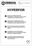
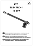
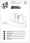
V2 S.p.A. Corso Principi di Piemonte, 65/67 - 12035 RACCONIGI (CN) ITALY tel. +39 01 72 81 24 11 [email protected] fax +39 01 72 84 050 www.v2home.com IL n. 311-1 EDIZ. 01/10/2008 HYPERFOR I ATTUATORE ELETTROMECCANICO TRIFASE PER CANCELLI SCORREVOLI FINO A 4000 KG DI PESO GB ELECTROMECHANICAL THREE-PHASE ACTUATOR FOR SLIDING GATES OF UP TO 4000 KG OF WEIGHT F ACTIONNEUR ÉLECTROMÉCANIQUE TRIPHASÉ POUR PORTAILS COULISSANTS JUSQU’À 4000 KG E ACTUADOR ELECTROMECÁNICO TRIFÁSICO PARA CANCELAS DESLIZABLES HASTA DE 4000 KG DE PESO For any installation problems please contact V2 S.p.A. TEL. (+39) 01 72 81 24 11 which can be consulted at the following web site: www.v2home.com CONFORMITY TO REGULATIONS V2 S.p.A. declares that the series of HYPERFOR actuators are in conformity with the provisions of the following EC directives: Please read this instruction manual very carefully 2006/95/CEE 89/336/CEE 99/05/CEE 98/37/CEE before installing and programming your control unit. • This instruction manual is only for qualified technicians, who specialize in installations and automations. • The contents of this instruction manual do not concern the end user. • Every programming and/or every maintenance service should be done only by qualified technicians. and with the standards referenced here below: • • • • • AUTOMATION MUST BE IMPLEMENTED IN COMPLIANCE WITH THE EUROPEAN REGULATIONS IN FORCE: EN 60204-1 EN 12445 EN 12453 low voltage electromagnetic compatibility radio directive machine directive EN EN EN EN EN 60335 - 1, EN 60335 - 2 - 103, 61000 - 2 - 3, EN 61000 - 3 - 3, EN 50336 55014 - 1, EN 55014 - 2 301 489 - 3 300 220 - 3 Note: Declares that the above mentioned devices may not be operated until the machine (automated gate) is identified, CElabeled, and declared to be compliant to the specifications of Directive 89/392/EEC and following modifications. (Machinery safety. electrical equipment of machines, part 1: general rules) (Safe use of automated locking devices, test methods) (Safe use of automated locking devices, requirements) The person in charge for the machine start-up must provide the following records: • Technical specification paper • Declaration of conformity • CE-labeling • Testing record • Maintenance record • Operation manual and directions • The installer must provide for a device (es. magnetotermical switch) ensuring the omnipolar sectioning of the equipment from the power supply. The standards require a separation of the contacts of at least 3 mm in each pole (EN 60335-1). • The plastic case has an IP55 insulation; to connect flexible or rigid pipes, use pipefittings having the same insulation level. Racconigi 20/06/2007 V2 S.p.A. legal representative A. Livio Costamagna • Installation requires mechanical and electrical skills, therefore it shall be carried out by qualified personnel only, who can issue the Compliance Certificate concerning the whole installation (Machine Directive 98/37/EEC, Annex IIA). • The automated vehicular gates shall comply with the following rules: EN 12453, EN 12445, EN 12978 as well as any local rule in force. • Also the automation upstream electric system shall comply with the laws and rules in force and be carried out workmanlike. • The door thrust force adjustment shall be measured by means of a proper tool and adjusted according to the max. limits, which EN 12453 allows. • We recommend to make use of an emergency button, to be installed by the automation (connected to the control unit STOP input) so that the gate may be immediately stopped in case of danger. • The appliance is not to be used by children or persons with reduced physical, sensory or mental capabilities, or lack of experience and knowledge, unless they have been given supervision or instruction. • Children being supervised do not play with the appliance. 7 ENGLISH V2 S.p.A. has the right to modify the product without previous notice; it also declines any responsibility to damage or injury to people or things caused by improper use or wrong installation. Gate maximum weight ENGLISH Power supply Nominal power 4000 Kg 400 VAC - 50Hz (collegamento a stella) 230 VAC - 50Hz (collegamento a triangolo) 1100 W Nominal absorption 2A Absorption at start 10 A Gate maximum speed 0,18 m/s Maximum thrust 4800 N Duty cicle (ambient temperature +55°C) Pinion Operation temperature Weight Protection 50 % M6-Z15 -20° ÷ +55°C 62 Kg IP55 8 levelled surface and parallel to the gate PREPARATORY STEPS CAREFULLY OBSERVE EUROPEAN REGULATIONS EN12445 AND EN12453 (WHICH REPLACE UNI 8612). ENGLISH Always check the following: • Your gate should have a strong and suitable build; no wickets should be present on the sliding gate. • The sliding gate should not tilt excessively during its entire run. • The gate should be able to slide freely on its guiding surface without an excessive friction. • Install both closing and opening limit switches, in order to prevent the gate going off the guiding surface. • Remove any manual locks. • Bring power cable ducts near the bottom of the gate (diameter 20 / 30 mm) and of the external devices (photocells, flasher, key selector). 5. Wait for the complete setting of the concrete 6. Unscrew the bolts fixing the base to the clamps and put the motor on the plate POSITIONING OF THE MOTOR To fix HYPERFOR, follow the instructions below: 7. Adjust the 4 grains F to make the motor be perfectly levelled 1. use the measurements indicated in the drawing for the foundations 8. Control that the motor is perfectly parallel to the gate, then insert the 4 washers R and lightly screw the 4 bolts D 2. Arrange for one or two pipes for the passage of electric cables 3. Assemble the 4 clamps on the anchoring plate and fix them with the 4 bolts issued with the motor 9 ENGLISH Release the motor and turn the gate completely open. Fix all the rack elements to the gate, making sure that they stand at the same height than the motor pinion. Check the following points: 1. the motor must be on a levelled surface and perfectly parallel to the gate 2. the distance between pinion and rack must be 1 or 2 mm. If needed, adjust the 4 grains 3. the rack must be trued up with the pinion of the motor 4. the minimum distance between the maximum overall of the gate and the case of the pinion of the motor must be of at least 5 mm Check the above indicated conditions and proceed fixing the 4 bolts D anchoring the motor to the plate. The rack MUST BE positioned 2 mm over the pinion of the motor all the gate length. INSTALLING THE MECHANICAL LIMIT SWITCHES Install limit switches on the rack and fix them using the screws provided in the tool kit. ATTENTION: check that the limit switch bracket will work effectively on the limit switch spring of the motor. If necessary add thickness between the lower part of the rack and the limit switch bracket in order to keep to the measurement as stated in the figure. 10 AND TORQUE LIMITING DEVICE ENGLISH In the absence of power, the gate can be released by operating on the motor: 1. Open the rear hatch 2. Loosen the allen screw L by using the equipped 4 mm-allen spanner 3. Screw anticlockwise (left thread) the metal ring K using the equipped 19 mm – spanner NOTE: operating on the metal ring, it is possible to set the built-in torque limiting device: Totally closed metal ring: torque = 0 Nm (motor released) Totally open metal ring: torque=220 Nm To 1. 2. 3. restart the automation proceed as follows: Screw clockwise the bolt K Tighten the allen screw L Close the rear hatch INSTALLATION LAYOUT WARNING: ALL THE CABLES USED FOR THE INSTALLATION MUST BE MARKED WITH T100°C. � Power supply cable 4 x 1,5 mm2 � Internal Photocellules � Blinker cable 2 x 1,5 mm � External Photocellules cable 4 x 0,5 mm2 (RX) cable 2 x 0,5 mm2 (TX) � External Aerial cable RG-58 � Safety edge (EN 12978) - � Digital or key selector cable 3 x 0,5 mm2 2 11 ................................................................................................................................................................ ENGLISH ................................................................................................................................................................ ................................................................................................................................................................ ................................................................................................................................................................ ................................................................................................................................................................ ................................................................................................................................................................ ................................................................................................................................................................ ................................................................................................................................................................ ................................................................................................................................................................ ................................................................................................................................................................ ................................................................................................................................................................ ................................................................................................................................................................ ................................................................................................................................................................ ................................................................................................................................................................ ................................................................................................................................................................ ................................................................................................................................................................ ................................................................................................................................................................ ................................................................................................................................................................ ................................................................................................................................................................ ................................................................................................................................................................ ................................................................................................................................................................ 12