1
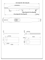
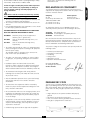
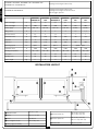
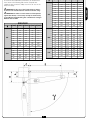
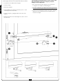
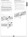
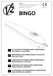
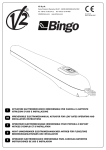
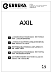
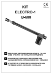
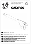
V2 S.p.A. Corso Principi di Piemonte, 65/67 12035 RACCONIGI (CN) ITALY tel. +39 01 72 81 24 11 - fax +39 01 72 84 050 [email protected] - www.v2home.com IL n.131 EDIZ. 20/10/2009 Bingo I ATTUATORE ELETTROMECCANICO IRREVERSIBILE PER CANCELLI A BATTENTE GB IRREVERSIBLE ELECTROMECHANICAL ACTUATOR FOR SWING GATES F OPERATEUR ELECTROMECANIQUE IRREVERSIBLE POUR PORTAILS BATTANTS E OPERADOR ELECTROMECÁNICO IRREVERSIBLE PARA CANCELAS BATIENTES P ACTUADOR ELECTROMECÂNICO IRREVERSÍVEL PARA PORTÕES DE BATENTE D NICHT UMKEHRBARER ELEKTROMECHANISCHER ANTRIEB FÜR FLÜGELTORE NL ELEKTROMECHANISCHE, ONOMKEERBARE LINEAIRE MOTOR VOOR HEKKEN MET VLEUGELS For any installation problem please contact our Customer Service at the number +39-0172.812411 operating Monday to Friday from 8:30 to 12:30 and from 14:00 to 18:00. which can be consulted at the following web site: www.v2home.com V2 has the right to modify the product without previous notice; it also declines any responsibility to damage or injury to people or things caused by improper use or wrong installation. DECLARATION OF CONFORMITY Please read this instruction manual very carefully before installing and programming your control unit. Company: V2 SPA Corso Principi di Piemonte 65 12035 RACCONIGI -ITALY Tel. +39 01 72 82 10 11 Fax +39 01 72 82 10 50 • This instruction manual is only for qualified technicians, who specialize in installations and automations. • The contents of this instruction manual do not concern the end user. • Every programming and/or every maintenance service should be done only by qualified technicians. V2 SPA declares that the series of BINGO actuators are in conformity with the provisions of the following EC directives: AUTOMATION MUST BE IMPLEMENTED IN COMPLIANCE WITH THE EUROPEAN REGULATIONS IN FORCE: EN 60204-1 EN 12445 EN 12453 Contact person: Cosimo De Falco Chief Executive Officer 73/23/EEC 89/366/CEE 98/37/EEC (Machinery safety electrical equipment of machines, part 1: general rules) (Safe use of automated locking devices, test methods) (Safe use of automated locking devices, requirements) low voltage directive electromagnetic compatibility directive machine directive Note: Declares that the above mentioned devices may not be operated until the machine (automated gate) is identified, CElabeled, and declared to be compliant to the specifications of Directive 89/392/EEC and following modifications. The person in charge for the machine start-up must provide the following records: • The installer must provide for a device (es. magnetotermical switch) ensuring the omnipolar sectioning of the equipment from the power supply. The standards require a separation of the contacts of at least 3 mm in each pole (EN 60335-1). • • • • • • • The plastic case has an IP55 insulation; to connect flexible or rigid pipes, use pipefittings having the same insulation level. Technical specification paper Declaration of conformity CE-labeling Testing record Maintenance record Operation manual and directions Racconigi 20/10/2009 V2 SPA legal representative Cosimo De Falco • Installation requires mechanical and electrical skills, therefore it shall be carried out by qualified personnel only, who can issue the Compliance Certificate concerning the whole installation (Machine Directive 98/37/EEC, Annex IIA). • The automated vehicular gates shall comply with the following rules: EN 12453, EN 12445, EN 12978 as well as any local rule in force. • Also the automation upstream electric system shall comply with the laws and rules in force and be carried out workmanlike. PREPARATORY STEPS The new series of actuadors BINGO, has been devised to serve gates up to 500 Kg with leaf up to 4,5 meters wide (look at the table technical data). Before proceeding with the installation, please make sure that your gate opens and closes freely, and that: • The door thrust force adjustment shall be measured by means of a proper tool and adjusted according to the max. limits, which EN 12453 allows. • We recommend to make use of an emergency button, to be installed by the automation (connected to the control unit STOP input) so that the gate may be immediately stopped in case of danger. • Hinges and pins are in optimum condition and properly greased. • No obstacles are within the moving area. • There is no friction with the ground or between the leaves. • Your gate is equipped with a central latch. • The appliance is not to be used by children or persons with reduced physical, sensory or mental capabilities, or lack of experience and knowledge, unless they have been given supervision or instruction. • Children being supervised do not play with the appliance. 7 ENGLISH The following statement is applicable only if the below listed equipments are employed in accordance with the purpose indicated in the instruction manual. ENGLISH BINGO400 - BINGO500 - BINGO400-120V - BINGO500-120V BINGO400-24V - BINGO500-24V Opening and closing mechanical stop BINGO400 02- BINGO500 02 Opening and closing mechanical stop Opening and closing electrical limit switch Built-in trigger capacitor BINGO400 BINGO400 02 BINGO400 120V BINGO500 BINGO500 02 BINGO500 120V BINGO400 24V BINGO500 24V Max. leaf lenght m 3,5 3,5 4,5 4,5 3,5 4,5 Max. leaf weight Kg 400 400 500 500 350 400 Power supply VAC - Hz 230 - 50 120 - 60 230 - 50 120 - 60 24 VDC 24 VDC Idling current A 2 4 2 4 1,8 1,8 Full load current A 3,2 6 3,2 6 5 5 Maximum Power W 480 480 480 480 120 120 Capacitor µF 8 2 x 10 8 2 x 10 - - Max travel mm 370 370 490 490 370 490 Operating speed m/s 0,017 0,018 0,017 0,018 Maximum thrust N 1800 1800 1800 1800 1800 1800 Working temperature °C -30 ÷ +60 -30 ÷ +60 -30 ÷ +60 -30 ÷ +60 -30 ÷ +60 -30 ÷ +60 Protection IP 34 34 34 34 34 34 Working cycle % 30 30 30 30 80 80 Motor weight Kg 11 11 12 12 11 12 0,010 ÷ 0,018 INSTALLATION LAYOUT � BINGO actuator cable 4 x 1 mm2 � Blinker cable 2 x 1,5 mm2 � Aerial cable RG-58 � Key or digital selector cable 3 x 0,5 mm2 � Safety edge (EN 12978) 8 � Internal photocells cable 4 x 0,5 mm2 (RX) cable 2 x 0,5 mm2 (TX) � External photocells cable 4 x 0,5 mm2 (RX) cable 2 x 1 0,5 mm2 (TX) � Control unit cable 3 x 1,5 mm2 γ To carry out a proper installation of the operator parts as well as to ensure the best automation performance, the measurement levels shown in the following table shall be complied with. Change the gate structure to adapt it to one of the cases in the table, if necessary. A [mm] B [mm] C [mm] D [mm] E [mm] 160 150 140 795 50 170 150 140 795 60 180 160 140 785 WARNING: In the case of leaf longer than 2,5 metres, 70 190 160 140 785 an electric lock must be fitted to ensure an efficent closig. 80 200 160 140 785 WARNING: In order to avoid contatcts of the operator 90 210 160 140 785 100 220 160 140 785 110 230 160 140 780 120 240 160 140 780 130 250 160 140 780 140 260 160 140 780 150 270 150 140 790 160 280 150 140 785 160 190 140 755 90° against the shutter, it is necessary to keep as much exactly as possible the height D taking into consideration a margin between 0 and +5mm. γ 90° 100° BINGO400 A [mm] B [mm] C [mm] D [mm] E [mm] 20 140 130 120 695 40 30 150 160 140 665 50 170 190 140 755 40 160 160 140 665 60 180 190 140 755 50 170 160 140 665 70 190 190 140 755 60 180 150 140 675 80 200 190 140 755 70 190 150 120 675 90 210 190 140 755 80 200 140 120 685 100 220 190 140 755 90 210 130 120 690 110 230 185 140 760 100 220 125 120 695 120 220 190 140 750 110 210 130 120 690 130 230 185 140 755 20 140 165 120 660 40 160 220 140 725 30 150 160 120 660 50 170 220 140 725 40 140 160 120 660 60 180 220 140 725 50 150 160 120 660 70 170 210 130 730 80 180 205 130 735 60 160 155 120 660 70 160 145 110 670 100° 110° 9 ENGLISH 40 Choose measures referring to the table you can find in the previous page, mark them on the pillars and continue as follows: side would be very difficult because of the conicity of the hole and the bush 3. An over forcing may cause the damage of some components. • Fix brackets on the pillars and on the gate. • Once inserted correctly the ring nut 2, fix it on the bush 3 using the screw 4 with its self-blocking nut. ENGLISH • Close the swing. • Unlock the actuators. • Close the self-blocking nut before hand moving the leaves. • Position BINGO on the brackets and fix the pin no. 1 with self-locking nut (see the picture). • Try more times to hand open and close the leaves, checking that there are no frictions between the actuator and the structure of the gate. • Insert the ring nut 2, paying attention to the side of the entrance. • Make that the hole for the fastening of the screw n. 4 is on the lower side. 10 Versions WITHOUT electric limit switch To adjust the limit switch, please do as follows: • Open the swing as much as possible and position the mechanical stop no. 1 in contact with the female screw. • Fasten the mechanical stop fixing the bolt using a 13 mm spanner. To adjust the limit switch, please do as follows: • Open the swing as much as possible and position the mechanical stop no. 1 in contact with the female screw. • Move the leave in closing position, then position the mechanical stop 2 next to the nut (keep a distance of at least 5 mm). • Fasten the mechanical stop fixing the bolt using a 13 mm spanner. PLEASE NOTE: Stop No. 2 must only be used for installations with no closure stop, or to intervene as a result of over-running under emergency conditions. • Close the swing as much as possible and position the mechanical stop no. 2 in contact with the female screw. Where the door has a mechanical stop, avoid setting stop No. 2 at the female screw end-stop when the gate is closing. The female screw could seize in such a way as to make it very difficult to release the Bingo. • Fasten the mechanical stop fixing the bolt using a 13 mm spanner. • Fasten the mechanical stop fixing the bolt using a 13 mm spanner. 11 ENGLISH Versions WITH electric limit switch As regards models equipped with electrical limit switches, the female screw stops 5mm before the mechanical stop; the electrical limit switch (already wired inside the motor) interrupts the motor power supply, to avoid unusefull stress and overheatings.