1
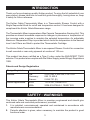
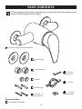
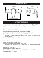
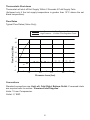
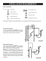
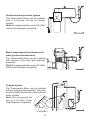
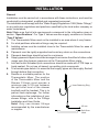
Kohler Odela
Thermostatic Mixer
Installation and User Guide
These instructions must be left with the user.
Contents
Introduction.............................................................................................. 3
Patents and Design Registration........................................................... 3
Safety : Warnings..................................................................................... 3
Pack Contents.......................................................................................... 4
Dimensions............................................................................................... 5
Specifications........................................................................................... 5
Pressures.............................................................................................. 5
Temperatures........................................................................................ 5
Thermostatic Shut-down....................................................................... 6
Flow Rates............................................................................................ 6
Connections.......................................................................................... 6
Installation Requirements....................................................................... 7
Installation................................................................................................ 9
General.................................................................................................. 9
1. Rear Entry Supplies (rising or falling concealed pipework)............. 10
2. Rising or Falling Supplies................................................................ 12
Reversed Inlet Supplies......................................................................... 14
Commissioning...................................................................................... 15
Maximum Temperature Setting........................................................... 15
Operation................................................................................................ 16
Fault Diagnosis....................................................................................... 17
Maintenance............................................................................................ 18
General................................................................................................ 18
Inlet Filters........................................................................................... 19
Type 2 Valves.......................................................................................... 21
Spare Parts............................................................................................. 22
Customer Service.....................................................................Back Page
If you experience any difficulty with the installation or operation of your new
Thermostatic Mixer, please refer to ‘Fault Diagnosis’, before contacting Kohler Mira
Ltd. Our telephone and fax numbers can be found on the back cover of this guide.
Introduction
Thank you for purchasing a quality Kohler product. To enjoy the full potential of your
new product, please take time to read this guide thoroughly, having done so, keep
it handy for future reference.
The Kohler Odela Thermostatic Mixer is a Thermostatic Shower Control with a
Single Sequential Knob for on/off and temperature control. It has been designed to
compliment the Kohler Odela Brassware range.
The Thermostatic Mixer incorporates a Wax Capsule Temperature Sensing Unit. This
provides an almost immediate response to changes in pressures or temperature of
the incoming water supplies to maintain the selected temperature. An adjustable
Maximum Temperature Stop is provided which limits the temperature to the desired
level. Inlet Filters are fitted to protect the Thermostatic Cartridge.
The Kohler Odela Thermostatic Mixer is an exposed Shower Control for connection
to wall mounted or rear entry pipework at centres of 153 mm.
This product has been certified as a Type 2 valve under the BUILDCERT TMV2
scheme. This product also complies with the Water Supply (water fittings) Regulations
1999.
Patents and Design Registration
Design Registration:
000555768-0003
Patents:
GB:2 291 693 2 392 225, 2 421 297
Germany:
695 13 455.8
France:
0 694 721 (E)
Patent Applications:
Euro:1 672 257, 03254070.0
USA:2006-0124758-A1, 10/607 025
Safety : Warnings
This Kohler Odela Thermostatic Mixer is precision engineered and should give
continued safe and controlled performance, provided:
1. It is installed, commissioned, operated and maintained in accordance with
manufacturers recommendations.
2. Periodic attention is given, when necessary, to maintain the product in good
functional order.
Pack Contents
Tick the appropriate boxes to familiarize yourself with the part names and to
confirm that the parts are included.
1 x Kohler Odela Thermostatic Mixer
2 x Concealing
Plates
2 x Compression
Nuts
1 x 2.5 mm
Hexagon Key
2 x Olives
1 x ‘O’ Key
2 x Wall Plugs
2 x No 8 x 1 ¼”
Securing Screws
Documentation
1 x Installation Template
1 x 12 L/Min
Flow Regulator
Dimensions
205 mm
132 mm
35 mm
153 mm (Pipe Centres)
Specifications
For Type 2 Valves, the supply conditions specified in section: ‘Type 2 Valves Application’ take precedence over the operating parameters which follow.
Pressures
Maximum Static Pressure: 10 Bar.
Minimum Maintained Pressure (Gas Water Heater): 1.0 Bar.
(for optimum performance supplies should be nominally equal).
Minimum Maintained Pressure (Gravity System): 0.1 Bar.
(0.1 bar = 1 Metre head from base of cold tank to the outlet of the
shower handset).
Maximum Maintained Pressure: 5 Bar.
Temperatures
Factory Pre-set (Blend) Shower: 43°C.
Optimum Thermostatic Control Range: 35°C - 45°C.
(Achieved with supplies of 15°C cold, 65°C hot and nominally equal
pressures).
Maximum Hot Supply: 85°C.
Recommended Hot Supply: 60°C - 65°C.
Minimum Differential between Hot Supply and Outlet Temperature: 10°C.
Cold Water Range: 5°C - 25°C.
Thermostatic Shut-down
Thermostat will shut off Hot Supply Within 2 Seconds if Cold Supply Fails.
(Achieved only if the hot supply temperature is greater than 10°C above the set
blend temperature).
Flow Rates
Typical Flow Rates (Valve Only)
Low Pressure - No Flow Regulator Fitted
High Pressure - 12 L/Min Flow Regulator Fitted
35
Flow Rate (L/Min)
30
25
20
15
10
5
0
0
1.0
2.0
3.0
4.0
5.0
Pressure Loss (bar)
Connections
Standard connections are: Hot-Left, Cold-Right, Bottom-Outlet. If reversed inlets
are required refer to section: ‘Reversed Inlet Supplies’.
Inlets: 15 mm Compression.
Outlet: ½” BSP.
Installation Requirements
Key to Symbols
Float Valve
Twin Impeller Pump
Isolating Valve
Single Impeller Pump
Thermostatic Mixer
Tempering Valve
Overflow Indicator
Mini Expansion Vessel
Pressure Reducing Valve
The Kohler Odela Thermostatic Mixer is compatible with the following systems:
Gravity fed system
The Thermostatic Mixer MUST be fed from
a cold water cistern and hot water cylinder
providing nominally equal pressure.
Gas heated system
The Thermostatic Mixer MUST be installed
with a gas water heater or combination
boiler of a fully modulating design.
Note! We recommend the use of a
12 L/Min Outlet Flow Regulator (supplied).
However, it is possible following the
installation of the Flow Regulator that the
flow rate is reduced too much for the boiler
to ignite. If this is the case remove the flow
regulator.
Unvented mains pressure system
The Thermostatic Mixer can be installed
with a unvented, stored hot water
cylinder.
Note! We recommend the use of a 12 L/Min
Outlet Flow Regulator (supplied).
Mains pressurised instantaneous hot
water system (thermal store)
The Thermostatic Mixer can be installed
with systems of this type with balanced
pressures.
Note! We recommend the use of a 12 L/Min
Outlet Flow Regulator (supplied).
Pumped system
The Thermostatic Mixer can be installed
with an inlet pump (twin impeller). The pump
must be installed on the floor next to the hot
water cylinder.
Note! We recommend the
use of a 12 L/Min Outlet
90°
Flow Regulator (supplied).
30°-60°
Air Separation
Installation
General
Installation must be carried out in accordance with these instructions, and must be
conducted by designated, qualified and competent personnel.
The installation must comply with the “Water Supply Regulations 1999 (Water Fittings)”
or any particular regulations and practices, specified by the local water company or
water undertakers.
Note! Make sure that all site requirements correspond to the information given in
section: ‘Specifications’. For Type 2 Valves see also supply conditions in section:
‘Type 2 Valves’.
1. The Thermostatic Mixer must not be installed in an area where it may freeze.
2. For stud partitions alternative fixings may be required.
3. Isolating valves must be installed close to the Thermostatic Mixer for ease of
maintenance.
4. Pipework must be rigidly supported and avoid any strain on the connections.
5. Pipework dead-legs should be kept to a minimum.
6.Supply pipework layout should be arranged to minimise the effect of other outlet
usage upon the dynamic pressures at the Thermostatic Mixer inlets.
7. Inlet and outlet threaded joint connections should be made with PTFE tape or
liquid sealant. Do not use oil-based, non-setting joint compounds.
8. To eliminate pipe debris it is essential that supply pipes are thoroughly flushed
through before final connection.
9.Decide on a suitable position for the
Thermostatic Mixer. The position
of the Thermostatic Mixer and the
Shower Fittings must provide a
Hose Retaining Ring
minimum gap of 25 mm between
the spill-over level of the shower
tray/bath and the handset. This is to
prevent back-siphonage. For further
information on the installation of your
shower fittings, refer to the Fittings
Installation and User Guide.
Note! Only use shower fittings
25 mm
recommended by the manufacturer
or supplier.
Spill Over
Level
Bend tabs inwards
Use as a support for the spirit level
153 mm
40 mm
Shower Control
Backplate Fixing Points
(Ø6 mm)
Hot Supply Inlet
(Ø15 mm)
18 mm from
finished wall
surface
Make sure that supply pipes are thoroughly flushed through
before connection to the shower control
Cold Supply Inlet
Bend tabs inwards
Use as a support for the spirit level
1. Rear Entry Supplies (rising or falling concealed pipework)
1.1 Use the Installation Template to mark
the positions of the holes for the
Backplate and the pipe centres.
Note! Allow a minimum of 150 mm
either side of the Thermostatic Mixer,
to allow access to the hot and cold
Inlet Filters for servicing.
1.2 For solid walls drill the Backplate
150 mm
holes with a 6 mm diameter drill 150 mm
153 mm
and insert the Wall Plugs (supplied).
For other types of wall structure
alternative fixing may be required (not
supplied).
1.3Drill the supply pipe holes at 153 mm
centres.
40 mm
1.4Recess the wall to allow for the
Concealing Plates, 32 mm diameter
x 10 mm deep.
10 mm depth x Ø32 mm
Note! Depth must be sufficient to
for Concealing Plates
prevent the Concealing Plates fouling
on the plumbing Elbows.
1.5 Fit the supply pipework (Hot - Left,
Cold - Right). The pipework must
Wall
Plugs
project 18 mm from the finished wall
153 mm
surface at 153 mm centres (use the
Installation Template as a guide).
Note! If the connections are reversed,
complete the installation then refer to
section: ‘Reversed Inlet Supplies’
before commissioning.
(Ø15 mm)
Backplate
32 mm
Elbow
10 mm minimum
between Elbow
and finished wall
surface
Securing Screws
Apply Silicone
Sealant
10
Concealing Plates
1.6Loosen the Grubscrew with the 2.5 mm Hexagon Key (supplied) and remove
the Backplate from the Thermostatic Mixer.
1.7Secure the Backplate to the wall using the Securing Screws (supplied).
1.8 Fit the Concealing Plates.
Note! Apply silicone sealant to the back face of the flange.
Caution! It is essential at this point that the supply pipework is thoroughly
flushed through before connection to the Thermostatic Mixer. Failure to do so
may result in product malfunction.
1.9 Fit the Compression Nuts and Olives onto the pipework.
1.10Align the Thermostatic Mixer with the pipework and fit onto the Backplate.
1.11Tighten the Compression Nuts onto the Thermostatic Mixer with a suitable
Spanner.
Caution! Take care not to damage the chrome surfaces.
Grubscrew
Flow Regulator
(for high pressure
systems)
1.12Tighten the Grubscrew with a 2.5 mm Hexagon Key (supplied) to secure the
Thermostatic Mixer to the Backplate.
1.13Fit the Shower Fittings, refer to your Fittings Installation and User Guide for
instructions.
Note! For high pressure systems, a 12 litre/minute flow regulator (supplied) can
be fitted under the hose washer.
1.14Turn on the hot and cold water supplies and check for leaks.
1.15The Maximum Temperature of the Thermostatic Mixer is factory set to approximately
43°C. If adjustment is required, refer to section: ‘Commissioning’.
11
35 mm
Bend tabs inwards
Use as a support for the spirit level
150 mm
153 mm
40 mm
Shower Control
Backplate Fixing Points
(Ø6 mm)
Hot Supply Inlet
(Ø15 mm)
Make sure that supply pipes are thoroughly flushed through
before connection to the shower control
40 mm
153 mm
Wall
Plugs
12
150 mm
153 mm
Cold Supply Inlet
(Ø15 mm)
Bend tabs inwards
Use as a support for the spirit level
2. Rising or Falling Supplies
2.1Loosen the Grubscrew on each Elbow
using the 2.5 mm Hexagon Key
(supplied) and rotate the Elbow 90° as
required. Retighten the Grubscrews.
2.2 Use the Installation Template to mark
the positions of the fixing holes for the
Backplate.
Note! Allow a minimum of 150 mm
either side of the Thermostatic Mixer,
to allow access to the hot and cold
Inlet Filters for servicing.
2.3 For solid walls drill the Backplate
holes with a 6 mm diameter drill
and insert the Wall Plugs (supplied).
For other types of wall structure
alternative fixing may be required (not
supplied).
2.4 Fit the supply pipework, 35 mm
from the finished wall surface
to the centre of the pipes
(Hot - Left, Cold - Right).
Note! Use the installation template to
set the distance from the wall (35 mm
centres / 153 mm apart).
Note! If the connections are reversed,
complete the installation then refer to
section: ‘Reversed Inlet Supplies’
before commissioning.
2.5Loosen the Grubscrew with the
2.5 mm Hexagon Key (supplied)
and remove the Backplate from the
Thermostatic Mixer.
35 mm
35 mm
2.6Secure the Backplate to the wall using
the Securing Screws (supplied).
Caution! It is essential at this point
that the supply pipework is thoroughly
flushed through before connection to
the Thermostatic Mixer. Failure to do so
may result in product malfunction.
2.7 Fit the Compression Nuts and Olives
onto the pipework.
2.8Align the Thermostatic Mixer with the
pipework and fit onto the Backplate.
2.9 Tighten the Compression Nuts onto
the Thermostatic Mixer with a suitable
Spanner.
Caution! Take care not to damage
the chrome surfaces.
2.10Tighten the Grubscrew to secure
the Thermostatic Mixer to the
Backplate.
2.11Fit the Shower Fittings, refer to your
Fittings Installation and User Guide
for Instructions.
Note! For high pressure systems,
a 12 litre/minute flow regulator
(supplied) can be fitted under the
hose washer.
2.12Turn on the hot and cold water
supplies and check for leaks.
2.13The Maximum Temperature of the
Thermostatic Mixer is factory set to
approximately 43°C. If adjustment
is required, refer to section:
‘Commissioning’.
13
Grubscrew
Flow Regulator
(for high pressure
systems)
Reversed Inlet Supplies
The Kohler Odela Thermostatic Mixer is supplied with inlet connections Hot-Left,
Cold-Right and Bottom-Outlet as standard. If the hot and cold water supply pipes have
been reversed during installation the following procedure must be performed.
1. Isolate the hot and cold water supplies.
2.Remove the Blanking Cap, loosen the Grubscrew and pull off the Control
Knob.
3. Pull off the Bearing.
4. Fit the ‘O’ Key (supplied) onto the Cartridge Nut and turn anticlockwise. Unscrew
fully and pull the Cartridge from the Body.
5.Rotate the Cartridge 180°.
6. Make sure that the two Cartridge Inlet Seals are fitted and carefully push into
the Body, aligning the Cartridge Lugs into the Body Slots.
Note! Make sure that the Cartridge Lug stamped ‘H’ is aligned with the hot inlet
supply.
Important! Take care when fitting the Cartridge as damage to the Cartridge
Inlet Seals may result in dripping from the Shower Head.
7. Tighten the Nut by turning the ‘O’ Key clockwise.
8. Refit the Bearing.
9. Refit the Control Knob, tighten the Grubscrew and refit the Blanking Cap.
10. Turn on the hot and cold water supplies and check for leaks.
11. The Maximum Temperature of the Thermostatic Mixer is factory set to approximately
43°C. If adjustment is required, refer to section: ‘Commissioning’.
‘O’ Key
Bearing
Control Knob
Grubscrew
Blanking Cap
14
Commissioning
Maximum Temperature Setting
The Maximum Temperature of the Thermostatic Mixer is factory set to approximately
43°C. If adjustment is required, set the maximum temperature as follows:
Note! Make sure that the hot water temperature is at least 10°C above the required
maximum showering temperature.
For Type 2 installations the maximum blend temperature is determined by the
application, refer to section: ‘Type 2 Valves - Application’.
1.Remove the Blanking Cap and loosen the Control Knob Grubscrew.
2. Turn on the Thermostatic Mixer to the maximum temperature (i.e. fully
anticlockwise) and allow the temperature to stabilise.
3. Pull off the Control Knob and Bearing.
4. Unscrew the Hub Retaining Screw with a 2.5 mm Hexagon Key (supplied).
Note! Do not remove the Hub.
5. Insert the 2.5 mm Hexagon Key into the centre of the Spindle and engage with
the recessed Temperature Adjusting Screw.
6. Rotate the Hexagon Key until the required maximum temperature is obtained
at the discharge point. Anticlockwise to increase the temperature, or clockwise
to decrease the temperature (¼ turn = 1°C).
7.Once the desired maximum blend temperature has been achieved turn off the
Thermostatic Mixer by rotating the Hub.
Note! Do not remove the Hub.
8. Refit the Hub Retaining Screw.
9. Refit the Control Knob and Bearing, tighten the Grubscrew and refit the Blanking
Cap.
Hub
Spindle
COLD
HOT
Control Knob
Hub Retaining
Screw
Grubscrew
Blanking Cap
15
Bearing
Operation
The Kohler Odela Thermostatic Mixer is a Thermostatic Shower Control with a Single
Sequential Control Knob for on/off and temperature control.
The Control Knob operates anti-clockwise in the following sequence:
Off
Maximum Preset
Temperature
Off
Cold
Warm
Maximum Preset Temperature
16
Fault Diagnosis
Symptom
Cause / Rectification
1.Only hot or cold a. Inlets reversed (hot supply to cold supply). Refer to
water from the
section: ‘Reversed Supplies’.
Thermostatic Mixer b. No hot water reaching the Thermostatic Mixer.
outlet.
c.Check the Filters for any blockage.
d. I n s t a l l a t i o n c o n d i t i o n s o u t s i d e o p e r a t i n g
parameters: refer to sections: ‘Specifications’
and ‘Commissioning’.
2. F l u c t u a t i n g o r a.Check the Showerhead, Hose and Filters for any
reduced flow rate.
blockage.
b.Make sure the maintained inlet pressures are
nominally balanced and sufficient, refer to section:
‘Specifications’.
c.Make sure the inlet temperature differentials are
sufficient, refer to section: ‘Specifications’.
d. Flow Regulator fitted incorrectly.
e.Airlock or partial blockage in pipework.
3. No flow from the a.Check the Showerhead, Hose and Filters for any
Thermostatic Mixer
blockage.
outlet.
b.Hot or cold supply failure.
4. Blend temperature a.Refer to symptom 2. above.
drift.
b. Significant supply temperature fluctuation.
c. Significant supply pressure fluctuation.
d. Faulty Thermostatic Cartridge, renew.
5.Maximum blend a. Indicates incorrect maximum temperature setting;
temperature setting
refer to section: ‘Commissioning’.
too hot or too cold. b.Refer to symptom 4. above.
6. Water leaking from a. Normal for a short period after shut off.
the Showerhead.
b.Check that the pressures are not in excess of the
specifications for product.
c.Cartridge Inlet Seals damaged, renew.
d.Renew the Thermostatic Cartridge.
7. Flow rate too low or a. (low) Insufficient supply pressures.
too high.
b. (high) Supply pressure too high. Install Flow Reg.
c.Refer to symptom 2. above.
17
Maintenance
General
This Product is precision engineered and should give continued safe and controlled
performance, provided:
1. It is installed, commissioned, operated and maintained in accordance with
manufacturers recommendations.
2. Periodic attention is given, when necessary, to maintain the product in good
functional order.
The Kohler Odela Thermostatic Mixer is designed for the minimum of maintenance
in normal use. If a malfunction occurs with the Thermostatic Cartridge then this will
necessitate a complete cartridge replacement.
Note! The cartridge contains no internally serviceable parts.
Lubricants
Silicone-only based lubricants can be used to assist in refitting.
Caution! Oil based or other lubricant types, may cause rapid deterioration of
seals.
Cleaning
Warning! Many household cleaners contain abrasive and chemical substances, and
should not be used for cleaning plated or plastic fittings. These finishes should be
cleaned using a mild washing up detergent or soap solution, rinsed and then wiped
dry with a soft cloth.
In-service Tests
The principle means for determining the continuing satisfactory performance of the
mixing vale is the in-service test.
Follow the procedure detailed in the flow diagram “In-service Test Procedure”.
Frequency of In-service Tests
Commercial (non-domestic installations)
Check for correct blend setting every 6 months.
Follow the procedure detailed in the flow diagram “In-service Test Procedure”, every
12 months.
18
Inlet Filters
Important! The Inlet Filters should be checked and cleaned as necessary every
12 months.
Note! The Inlet Filters must not be removed except for cleaning. If the Thermostatic
Mixer is operated without the Inlet Filters fitted the Warranty on the product will be
void.
1. Isolate the hot and cold water supplies and operate the Control Knob to drain
any residual water.
2. Unscrew the Filter Blanking Caps then unscrew the Filter Caps with the ‘O Key’
(supplied) or a 12 mm hexagonal wrench and remove the Filters.
3.Clean each Filter in turn under a jet of water to remove any lodged particles.
4. Refit the Filters and tighten the Filter Caps.
Note! Make sure that the seal is fitted correctly and not damaged.
5. Refit the Filter Blanking Caps.
6. Turn on the hot and cold water supplies and check for leaks.
Filter
‘O’ Seal
Filter Cap
Filter Blanking
Cap
19
Start
Measure and record supply
temperatures and pressures. Make sure
that they are within Valve specifications.
Measure and record blend
temperature(Tb) and flow rate.
Has flow rate fallen
significantly or fallen
below minimum flow
specification?
Yes
Check and clean checkvalves,
strainers and outlet.
Measure and record blend
temperature(Tb) and flow rate.
No
Yes
Carry out a performance check. Refer
to the commissioning procedure.
Has the blend
temperature changed
by more than 2°C from
previous recorded
value(Tb)?
Has flow rate
improved?
No
Yes
No
Refer to section: ‘Fault
Diagnosis’.
Finish
Carry out the commissioning
procedure.
Note! All measurements and results should be recorded in the Log Book.
Flow Diagram, In-service Test Procedure
20
Type 2 Valves
Application
The approved designations for Type 2 Valves are as follows:
Model
Designation
Kohler Odela
LP-S, HP-S
The permitted application details are:
Designation
Operating
Pressure Range
Application
Mixed Water
Temperature†°C
LP-S
Low Pressure
Shower
41°C Maximum
HP-S
High Pressure
Shower
41°C Maximum
Mixed water temperature at discharge point.
Important! For TMV2 installations the mixed water temperature at the discharge
point should never exceed 46°C.
In order to achieve the safe water temperatures expected of a Type 2 Valve it is
essential that the valve is used only for the applications covered by its approved
designations, with the appropriate water supply pressures and temperatures, and it
is commissioned, maintained and serviced in accordance with the recommendations
contained in this guide (refer to the section ‘Maintenance, In-Service Tests’
for in service test frequency that must be used as a minimum guide in Type 2
installations).
†
Supply Conditions
For applications where a Type 2 Valve is required, the supply conditions must comply
with the values in the Table below. Note that both hot and cold supply pressures
must lie within the same pressure range.
Operating Pressure
Range
High Pressure
Low Pressure
Maximum Static
Pressure (bar)
10
10
Maintained Pressure,
Hot and Cold (bar)
1 to 5
0.2 to 1
Hot Supply
Temperature (°C)
55 to 65
55 to 65
Cold Supply
≤ 25
≤ 25
Temperature (°C)
Valves operating outside these conditions cannot be guaranteed to operate as
Type 2 Valves.
21
Spare Parts
1062470Seal Pack (illustrated ‘A’)
1062471Component Pack with Flow Regulator
1062474Cartridge Assembly
1062476
Backplate
1062477
Filter Pack (x 2)
1062478
Inlet Connector
1062479Outlet Connector
1063660Screw Pack (illustrated ‘B’)
1063661Compression Fitting Kit
1063663
Bearing
1063665
Filter Cap (x 2)
1063667Elbow Pack
1063669Handle
1063671
‘O’Key
1617.196Hub Pack
22
1063665
A
1062477
A
B
1062476
A
1063667
A
B
1062478
1062474
1063661
1063663
A
1062479
A
B
1617.196
B
1062471
1063669
B
1063671
23
Customer Service
Guarantee of Quality
Kohler UK guarantee products against any defect of materials or workmanship for the following periods
Ceramic Ware and Cast Products
Shower Valves, Taps, Cistern
Fittings, Toilet Seats and Bath
Panels
Stainless Steel Products and, Acrylic Baths
Bathroom Furniture and
Accessories
Whirlpool / Spa Baths
Our confidence in the quality and reliability of our superior products enables us to offer a
comprehensive guarantee for all products.
To Contact Us
To register and fully benefit from this guarantee you must
return the enclosed product registration card indicating
the Kohler items you have purchased.
Within the guarantee period we will undertake to resolve
any material defects, by providing replacement parts,
modules or complete product, as we deem appropriate.
To be free of charge, work must only be undertaken by
Kohler UK approved personnel.
To ensure that any problems can be promptly resolved
you must contact Kohler UK directly.
Proof of purchase must be provided with any claims.
Kitchen and Bathroom Taps and Accessories
Tel: 0870 240 7896
Fax: 01242 282 595
Email: [email protected]
Website: www.kohleruk.com
Showers and Fittings
Tel: 0870 241 0888
Fax: 01242 282 595
Email: [email protected]
Website: www.kohleruk.com
This guarantee covers products in domestic use, installed
and maintained in accordance with the instructions. It
covers the purchaser only and is not transferable.
All other Kohler Products
Tel: 0870 850 5551
Fax: 0870 850 5552
Email: [email protected]
Website: www.kohleruk.com
Commercial / Business Use
Any Kohler Bathroom product used within a commercial /
business premise is guaranteed for 1 Year against any
defect of materials or workmanship.
Not Covered by this Guarantee
Damage or defects arising from incorrect installation,
improper use or lack of maintenance.
Installed product damaged in transit Consequential loss,
damage or product removal and installation costs.
General wear and tear.
This guarantee is in addition to your statutory and other
legal rights.
1062921-W2-C (1635)
24
© Kohler Mira Limited, November 2006