1
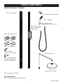
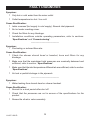
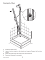
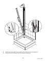
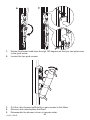
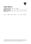
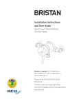
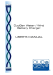
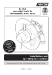
Amicio Shower Column
These instructions must be left with the user
Installation and User Guide
1
1114271-W2-D
INTRODUCTION
Thank you for purchasing a quality KOHLER® product. To enjoy the full potential of
your new product, please take time to read this guide thoroughly, having done so,
keep it handy for future reference. The following pages aim to provide comprehensive
installation instructions, plus advice on how to care and maintain your product.
We recommend that the unit is installed by a qualified plumber or engineer.
General
1.
2.
3.
4.
Read all of these instructions.
Retain this guide for later use.
Pass on this guide in the event of change of ownership of the installation site.
Follow all warnings, cautions and instructions contained in this guide.
GUARANTEE
For domestic installations, Kohler guarantee the Amicio Shower Column against
any defect in materials or workmanship for a period of five years from the date of
purchase (shower fittings for one year).
For non-domestic installations, Kohler guarantee the Amicio Shower Column
against any defect in materials or workmanship for a period of one year from the
date of purchase. For terms and conditions refer to the back cover of this guide.
RECOMMENDED USAGE
Application
Shower Column and Fittings
Domestic
ü
Light Commercial
ü
Heavy Commercial
û
Healthcare
û
TOOLS REQUIRED
6.0 mm
1114271-W2-D
2
PACK CONTENTS
Amicio Shower Column
q 1 x Wall Channel
q 1 x Magnetic Clamp Bracket
q 1 x Handset
q 1 x Shower Hose
q 1 x Front Fascia
(supplied with 2 x hose seals)
and Thermostatic
Mixing Valve
q 1 x Component Pack
q 4 x Wall Plugs
q 4 x Fixing Screws
q 2 x Screws
(Drench Arm Housing)
q 1 x Drench Arm
q 3 x Fixing Screws
(Optional fixing screws
for panel installation)
q 1 x Drench Head
q 1 x Installation Template
Documentation
q 1 x Guarantee Registration Document
3
1114271-W2-D
IMPORTANT SAFETY INFORMATION
1.
2.
3.
Read all of these instructions.
Follow all warnings, cautions and instructions contained in this guide.
The clamp bracket contains a magnet. Users fitted with a heart pacemaker
or ICD should follow their normal safety precautions for products that contain
magnets. There are no magnets in the showerhead.
SPECIFICATIONS
Pressures
•
•
•
Max Static Pressure: 10 Bar.
•
For optimum performance supplies should be nominally equal.
Max Maintained Pressure: 5 Bar.
Min Maintained Pressure (Gravity System): 0.1 Bar. (0.1 bar = 1 Metre head
from cold tank base to overhead showerhead).
Temperatures
•
•
Factory Pre-set (Blend) Shower: 43°C.
•
Recommended Hot Supply: 60°C to 65°C Note! The mixing valve can operate
at higher temperatures for short periods without damage, however this could
detrimentally affect thermostatic performance. For safety and performance
reasons it is recommended that the maximum hot water temperature is limited
to 65°C.
•
•
Cold Water Range: up to 25°C.
Optimum Thermostatic Control Range: 35°C to 43°C (achieved with supplies
of 15°C cold, 65°C hot and nominally equal pressures).
Minimum Recommended Differential between Hot Supply and Outlet
Temperature: 12°C.
Thermostatic Shut-down
•
For safety and comfort the thermostat will shut off the mixing valve within 2
Seconds if either supply fails. (achieved only if the blend temperature has a
minimum differential of 12°C from either supply temperature).
1114271-W2-D
4
INSTALLATION
Install the Shower Column
1
Note! The installation template
can be used on either wall to
suit your particular application.
(a) Use the installation template (supplied) to mark the positions for the holes for
the pipes.
2
C
35 mm
Max
H 35 mm
25 mm
Max
(a) Install the hot and cold pipework as shown in the above diagram.
Note! We recommend using end feed/solder fittings as compression or push
fit fittings may prevent the front fascia clipping the wall channel.
Note! Individual hot and cold isolating valves must be fitted in the supply pipes
outside of the showering area.
Caution! It is essential at this point that the supply pipework is thoroughly
flushed through before connection to the mixer. Failure to do so may result
in product malfunction and will not be covered under the guarantee.
Cover the end of the pipework with some tape to make sure that no debris
falls into the pipes when drilling.
5
1114271-W2-D
3
915 mm (36”)
(a) Hold the wall channel in position on the shower tray and make sure that it is
upright.
(b) If the distance between the drench arm housing and the ceiling is less than
915 mm (36”), temporarily install the drench arm before fixing the wall channel
to the wall.
b
4
a
Ø 6 mm
c
d
1114271-W2-D
6
(a) Put the wall channel in position on the shower tray.
(b) Using a spirit level make sure that the wall channel is upright.
(c) Mark the positions for the fixing holes on one side of the channel (3 off), then
remove the wall channel.
Note! There are three fixing holes on each side of the wall channel. It is better
to use the fixing holes on only one side of the wall channel. This is to ensure
that the wall channel does not become distorted on uneven wall surfaces.
Note! For added stability the centre screw hole on the other side of the wall
channel can be used, but care must be taken that you do not distort the wall
channel when tightening the screw.
Note! The optional fixing screws (3 off) can be used for extra stability if the wall
channel is against an aluminium extrusion from the shower enclosure.
Note! Make sure that you avoid any hidden cables or pipes when you drill into
the walls.
(d) For solid walls, drill with a 6 mm masonry bit (not supplied) and plug using the
wall plugs (supplied).
Note! For other types of wall structure alternative fixings may be required.
(e) Put the wall channel in position and partially install the fixing screws.
5
(a) Screw the drench head onto the drench arm.
(b) Do not overtighten.
7
1114271-W2-D
6
(a) If not already fitted, insert the drench arm through the drench arm housing.
7
Suitable Height For
All Users
(a) Move the drench arm up or down so that the drench head is at a suitable height
and showering position for all users.
(b) Lock the drench arm in position by tightening the three grub screws. Make sure
that the drench arm is at the correct angle.
8
1114271-W2-D
8
OFF
ON
(a) Locate the front fascia in the clips at the bottom of the wall channel and connect
the flexible pipes (Hot and Cold identified) to the hot and cold water supplies.
Make sure that the push fit connectors are fully engaged.
(b) With the levers on the mixing valve set to the off position turn on the water
supply and check for leaks.
(c) If no leaks are present turn off the water supply.
9
1114271-W2-D
9
Drench Arm
Fascia
Plastic
Outlet Pipe
(a) Remove the push fit connector from the plastic outlet pipe.
(b) To ensure that the pipe is not too long when cut off, move the fascia as close
as possible to the wall channel and mark with a pencil the plastic outlet pipe
against the end of the drench arm
(c) Cut the pipe as shown in the above diagram making sure that there are no
sharp edges on the end of the pipe.
(d) Fit the push fit connector over the end of the pipe and then onto the end of the
drench arm. Make sure that the push fit connector is fully engaged.
10
1114271-W2-D
10
Loosen the two back screws
Drench Arm Housing
(a) Loosen the back two screws on the drench arm housing.
(b) Lift the drench arm slightly so that the top of the fascia fits beneath the drench
arm housing.
(c) Push the front fascia onto the wall channel until it clicks into position along its
length. Make sure that it locates correctly over the clips at the bottom of the
wall channel.
(d) Once the front fascia is in position, install the front screws to the drench arm
housing and tighten the back screws to secure in position.
11
1114271-W2-D
11
Install the Shelf (Optional Accessory)
a
b
(a) The shelf comes fully assembled and needs disassembling before you fit it to
the shower valve
1114271-W2-D
12
12
(a) Connect one end of the shower hose to the valve outlet and the other end to
the showerhead. Make sure that the hose seals are installed correctly.
Note! The end of the hose with two flats is attached to the valve and the end
without the flats to the handset.
(b) Install the handset holder on the front face of the shower panel (with the drain
hole at the bottom).
Note! The handset holder is magnetic and will stick anywhere above the shower
valve.
Note! Make sure the rubber base of the magnetic spray holder is clean of all
debris before attaching to the fascia for first time.
(c) Fit the handset in the handset holder.
Note! There are two positions for the handset within the holder to enable the
user to change the angle.
13
1114271-W2-D
OPERATION
Amicio Shower Column
Turn the temperature control
lever clockwise to decrease
the temperature and anticlockwise
to the preset maximum temperature
-
+
OFF
ON
Turn the flow lever
clockwise to the
maximum flow
Turn the divertor lever clockwise
to select the handset, anticlockwise
to select the drench head.
Mid point to select both the handset
and the drench head.
1114271-W2-D
14
COMMISSIONING
Maximum Temperature Setting
Before using the shower the maximum temperature must be checked to make sure
that it is at a safe level. It has been preset to approximately 43°C at the factory but
due to variations in site conditions the maximum temperature may need adjustment.
Note! Make sure that the hot water temperature is at least 55°C and that there is
sufficient supply.
1. Turn on the mixer to the maximum temperature (i.e. fully anticlockwise) and
allow the temperature to stabilise.
2. Test that the temperature of the water from the shower outlet is hot enough.
If the temperature is too hot or too cold adjust as follows:
3. Carefully remove the concealing cap using a suitable tool.
4. Unscrew the securing screw and remove the temperature lever bearing.
5. Lift the temperature lever and move it back one serration on the temperature
control gear.
6. Return the lever to the maximum temperature stop and check the temperature,
if it is still not hot enough repeat the procedure.
Concealing Cap
Rubber Seal
Lift the temperature lever and
move back one serration
Securing Screw
Temperature Lever
Bearing
Re-engage with the
control gear and
return to the maximum
temperature stop
7.
8.
Once the maximum temperature is satisfactory, refit the temperature control
bearing and fit and tighten the securing screw.
Refit the concealing cap, make sure that the rubber seal is correctly fitted.
15
1114271-W2-D
FAULT DIAGNOSIS
Symptom:
• Only hot or cold water from the mixer outlet.
•
Outlet temperature too hot / too cold.
Cause Rectification:
• Inlets reversed (hot supply to cold supply). Rework inlet pipework.
•
•
•
No hot water reaching mixer.
Check the filters for any blockage.
Installation conditions outside operating parameters, refer to sections:
‘Specifications’ and ‘Commissioning’.
—————————————
Symptom:
• Fluctuating or reduced flow rate.
Cause Rectification:
• Check the shower drench head or handset, hose and filters for any
blockage.
•
•
•
Make sure that the maintained inlet pressures are nominally balanced and
sufficient, refer to section: ‘Specifications’.
Make sure that the inlet temperature differentials are sufficient, refer to section:
‘Specifications’.
Air lock or partial blockage in the pipework.
—————————————
Symptom:
• Water leaking from drench head or shower handset.
Cause Rectification:
• Normal for a short period after shut off.
•
Check that the pressures are not in excess of the specifications for the
product.
•
Renew the divertor valve assembly.
1114271-W2-D
16
MAINTENANCE
General Maintenance
Providing the shower column has been correctly installed and is operated in
accordance with the instructions contained in this guide, difficulties should not arise.
If any maintenance is required then it must be carried out by a competent tradesperson
to whom the maintenance instructions are provided.
Before replacing any parts ensure the underlying cause of the malfunction has been
resolved.
Cleaning
Warning! Many household cleaners contain abrasive and chemical substances and
should not be used for cleaning painted, plated or plastic fittings.
These finishes should be cleaned with a mild washing up detergent or soap solution
and then wiped dry using a soft cloth.
Chrome Parts
Use only cleansers expressly specified for chrome!
17
1114271-W2-D
Cleaning the Filters
1.
2.
3.
4.
Isolate the water supply.
Loosen the four screws on the drench arm housing. Remove the front two
screws.
Gently lift up the drench arm and pull the front fascia off.
Disconnect the push fit connection.
1114271-W2-D
18
1.
2.
Disconnect the push fit connections from the hot and cold supplies.
Remove the front fascia from the shower enclosure.
19
1114271-W2-D
a
1.
2.
1.
2.
3.
b
Rotate the shower head hose through 180 degrees so that you can get access
to the grub screw.
Loosen the two grub screws.
Pull the valve forward sufficiently to gain access to the filters.
Remove and clean/replace the filters.
Reassemble the shower column in reverse order.
20
1114271-W2-D
ACCESSORIES
Genuine accessories can be purchased direct from Customers Services (our
contact details can be found on the back cover of this guide) or from approved
stockists or merchants.
Shelf Glass - 400893
A glass shelf that can be fitted to the bottom of the
valve assembly.
21
1114271-W2-D
SPARE PARTS
1690.070
Drench Head Arm
1690.069
Drench Head
1690.071
Arm Support
1690.065
Divertor Pipe
1690.064
Handset Holder
1690.067
Handset
1690.051
Backplate
Assembly
1690.051
Backplate
Assembly
1690.068
Shroud
A
1690.072
Flexible Pipes
and Push Fit 1736.739
Connection
Hose
1690.073
Base Cap
1114271-W2-D
1690.080 - Wall Channel 1870 mm
1690.081 - Wall Channel 1900 mm
1690.082 - Wall Channel 1950 mm
22
400893
Shelf
1690.077
Fascia 1870 mm
1690.078
Fascia 1900 mm
1690.079
Fascia 1950 mm
A
1690.044
Temperature Lever
1660.152
Filter Pack
1690.046
Valve Body
1690.045
Flow Lever
1690.050
Divertor Connector
1690.048
Divertor Valve
1690.065
Divertor Pipe
1690.049
Divertor Lever
23
1114271-W2-D
CUSTOMER SERVICE
Guarantee
Helpdesk Service
Your product has the benefit of our manufacturers
guarantee which starts from the date of purchase.
To activate this guarantee, please return your completed
registration card, visit our website or free phone 0800
0731248 within 30 days of purchase (UK only).
Within the guarantee period we will resolve defects in
materials or workmanship by either repairing the product,
providing new goods and parts to you in replacement or
refunding (up to but not in excess of) the original purchase
price, as we may choose.
This guarantee is in addition to your statutory rights
and is subject to the following conditions:
● The guarantee applies solely to the original installation
under normal domestic use and to the original
purchaser only.
● The product must be installed and maintained in
accordance with the instructions given in this guide.
● The product must be inspected and issues reported
before installation.
● Servicing must only be undertaken by us or our
appointed representative. Note! if a service visit
is required the product must be fully installed and
connected to services.
● Repair under this guarantee does not extend the original
expiry date.
● The guarantee on any replacement parts or products
ends at the original expiry date.
● For shower fittings or consumable items we reserve
the right to supply replacement parts only.
The guarantee does not cover:
● Call out charges for non product faults (such as
damage or performance issues arising from incorrect
installation, improper use, inappropriate cleaning,
lack of maintenance, build up of limescale, frost
damage, corrosion, system debris or blocked filters)
or where no fault has been found with the product.
● Water or electrical supply, waste and isolation issues.
● Compensation for loss of use of the product or
consequential or indirect loss of any kind.
● Damage or defects caused if the product is repaired
or modified by persons not authorised by us or our
appointed representative.
● Routine maintanance or replacement parts to
comply with the requirements of the TMV2 or TMV3
helathcare schemes.
● Accidental or wilful damage.
● Product purchased ex-showroom display.
Our Customer Services Team is comprehensively
trained and can offer help and advice, spare
parts, accessories or a service visit.
We will need you to have your model name,
model number and date of purchase.
KOHLER® Website (www.KOHLER.co.uk)
From our website you can download additional
user guides or request a service visit.
Spares and Accessories
We hold the largest stocks of genuine Kohler
spares and accessories.
Contact us for a price and to purchase spares
or accessories.
Service / Repairs
No one knows our products better than our
nationwide team of Service Technicians. We can
carry out service or repair work to your product
both during and after the guarantee period.
Ask about our fixed price service repairs.
To Contact Us: UK
0844 571 0048
Fax: 0844 571 7157
E-mail: [email protected]
Eire Only
0044 844 571 0048
Fax: 0044 844 571 7157
What to do if something goes wrong
If your product does not function correctly when you first
use it, contact your installer to check that it is installed in
accordance with the instructions in this manual.
If this does not resolve the issue, contact our Customer
Services Team who will offer you or your installer help
and advice.
By Post:
Kohler Mira Limited
Customer Services Dept,
1 Penrose Place,
Skelmersdale,
WN8 9PR
Kohler is a registered trade mark.
The company reserves the right to alter
product specifications without notice.
1114271-W2-D (B94 Fb)
Kohler Mira Limited
Customer Services Dept,
1 Penrose Place,
Skelmersdale,
WN8 9PR
24
© Kohler Co. March 2013