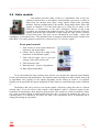
1
The Cairn Research
Modular Photometry System
User Guide V2.0
Rack mounted fluorescence detection system
________________________________________________________________________________
I. Package Contents
Control box style
q
Single height system rack
q
Double height system rack
Control Modules
q
Input signal amplifier module
q
Photomultiplier signal amplifier module
q
Photomultiplier power supply module
q
Signal ratio module
q
Signal output demultiplexing module
q
Signal gain / offset module
q
Metering module
q
Signal combiner module
Emission Hardware
q
Adjustable rectangular diaphragm and holder
q
Single emission coupling box (with appropriate dichroic mirror fitted)
q
Dual emission coupling box (with appropriate dichroic mirrors fitted)
q
Two position filter holder (with appropriate filter fitted)
q
Photomultiplier
q
CCD camera & power supply
q
Monitor
Cabling
q
HV PMT lead
q
BNC leads
q
Mains Power lead
_________________________________________________________________________Page
_________________________________________________________________Package contents
_________________________________________________________________________Page
________________________________________________________________________________
II. Table of Contents
I. Package Contents.............................................................................................................................ii
II. Table of Contents...........................................................................................................................iv
_________________________________________________________________________Page
_________________________________________________________________Package contents
1
Introduction
The Cairn fluorescence system is by far the most versatile photometry equipment available. The
design is modular, allowing a system to be configured to the user's individual needs, or to be
changed or extended according to future requirements. The system is particularly suitable for
dual (or multiple) excitation measurements, but dual emission measurements can also be
made, using either single-wavelength or multiple-wavelength excitation. It can be connected
to most popular microscopes, including those made by Nikon, Olympus, Leica and Zeiss, or
it can also be used with our own cuvette holder for cell suspension measurements. A
particularly important feature is the ease with which it can be interconnected with other
equipment. Not only can our system accept other signals that are being monitored at the
same time, but it can also provide a full range of outputs that can be sent to other equipment.
This means that you can get started by adding Cairn components to an existing experimental
set-up, while retaining the option of extending it to a full Cairn system at any time in the
future.
We are a fully independent Company, and we plough back a significant proportion of our turnover
into the design of new products. Not only is our fluorescence range still being extended, but
as the Company grows we are also moving into other product areas, such as
electrophysiology. A key part of our strategy has been to design and manufacture equipment
that gives our customers a competitive advantage in the advancement of science, and to
achieve this aim we produce most system components ourselves. We now have our own
versions of many items that we previously obtained from other manufacturers, such as light
sources and a variety of microscope accessories, and this has enabled us to provide
substantially improved performance at lower prices. A particular advantage of this strategy is
that we know the equipment inside out, so we can repair it very quickly if it ever does go
wrong.
The company philosophy is flexibility and responsiveness, as you are probably already aware. We
know your experimental time is valuable and we therefore endeavour to provide the very
highest levels of service and support, whether you are just an hour or two away or are on the
other side of the world. We aim to respond to technical queries within 24 hours. Full contact
details are given at the end of the manual.
_________________________________________________________________________Page
________________________________________________________________________________
_________________________________________________________________________Page
_________________________________________________________________Package contents
2
Installation guide
Before beginning to install a Cairn system it is advisable to have to hand an oscilloscope (any age
or condition is fine provided that it’s not completely dead!), screwdrivers, allen keys, and
safety glasses. We would also urge our customers to take some time to carefully check the
delivery note to make sure that they can identify all the components. Having checked that all
components are present and correct the next step is to assemble and test the different sections
of the system.
2.1 Emission detection components
Adjustable diaphragm
Emission coupling box
(Dual emission coupling shown fitted with
two dichroic mirror holders)
Filter holder & slider
PMT housing
_________________________________________________________________________Page
________________________________________________________________________________
CCD camera
Monitor
(Shown with TV lens attached)
2.2 Emission detection hardware installation
The Cairn emission detection hardware is designed for connection to the C-mount of a
research microscope. The dichroic mirrors and lens positions are pre-configured at Cairn and the
components will normally be supplied fully assembled for direct coupling onto the C-mount. After
locating the detection components, the appropriate cabling should be made. The photomultipliers
have two connections to be made to the control modules. The HV BNC should be connected to the
PMT supply module using the HV lead supplied, and the output BNC connected to the PMT
amplifier input using a standard BNC lead. If additional photomultiplier tubes are present, they
must be connected to separate PMT supply and amplifier modules. The acquired signals from
wavelength positions 1-8 will be available at positions 1-8 on the output module by default, and
connections to external data acquisition and recording systems should be made here. If supplied,
the CCD camera will need to be connected to a DC power supply (supplied) and its output
connected to the monitor using a BNC cable and adapter (supplied).
The infrared viewing system allows the experiment to be monitored visually both prior to and
during experiments. It is an important supplement to viewing through the microscope eyepieces as
it allows the experimenter to see the precise region of interest being monitored by the
photodetectors, without interfering with the fluorescence signals. It incorporates several of the
items already detailed, but is best tested in its entirety. Correct operation should be verified, with
the photomultiplier(s) switched off or the cabling disconnected, as follows:
1. Connect the full detection assembly to the microscope with the CCD camera and monitor
connected and switched on.
2. Install the 715nm or 780nm long pass infrared illumination filter in the microscope, but position
it so that it is NOT in the light path at this stage.
N.B. The filter should fit into either a sliding or rotating assembly in the transmitted light path
so that it can be easily removed when viewing through the eyepieces.
3. Focus a typical test sample (e.g. some unloaded cells) using the eyepieces.
1. Insert the infrared filter and divert the light path to the photometric output port using the
appropriate lever or dial on the microscope.
2. Adjust the illumination level of the microscope light source until the diaphragm blades and the
image of the test object are clearly visible on the monitor.
_________________________________________________________________________Page
_________________________________________________________________Package contents
3. The microscope should require only minimal readjustment to attain best focus on the CCD
camera. Adjustment of the microscope C-mount will allow matching of the image planes seen
through the side port and eyepieces. If significant refocusing is needed when switching between
the side port and the eyepieces, or if the object and diaphragm are not parfocal then please
consult with us.
4. The field of view on the monitor will probably be more restricted than that viewed through the
eyepieces. If however a suitably sized object cannot be “framed” properly on the monitor then
please contact us to determine which accessory optics are required.
5. Verify the opening and closing, rotation, and lateral movement of the rectangular diaphragm. If
the blades are dirty the diaphragm should be removed, allowing the blades to be cleaned using a
pressurised air jet or a matchstick. The diaphragm can be removed from its holder by releasing
the two knurled grubscrews normally used for rotation, then sliding it out of the holder. There
may be slight imperfections on the edges of the diaphragm blades, even after cleaning. This is
normal and will not affect its performance.
_________________________________________________________________________Page
________________________________________________________________________________
_________________________________________________________________________Page
0
_________________________________________________________________Package contents
3
Signal control modules
The signal control modules have been designed for use with our full range of wavelength
control and signal detection equipment, and as such are extremely flexible in their modes of
operation. The modules are designed to fit our rack based systems and communicate between each
other using an internal back plane. The number of positions available for modules depends on the
system configuration. A standard single height rack will accommodate up to three modules with
built in Optoscan or Optospin controller, and up to six without the controller. The double height
rack has provision for an additional seven modules in each case. An outline of the operation of each
of the modules is given here, with further details provided in the technical reference.
3.1 PMT supply module
This module provides the high voltage power needed to drive the
photomultiplier tube. It is continuously variable from 0 to 2000V with the
meter displaying the voltage currently being applied to the photomultiplier.
The connector on the front panel is a special HV connector and should only be
used with HV leads and NOT standard BNC leads. Failure to do so can lead to
costly equipment damage. Spare HV leads are available from us if you lose or
damage the ones supplied.
We would recommend leaving the power supply in the off position when
not in use to avoid accidental damage to the equipment through over exposure to light. As an
additional precaution when setting up or performing a new series of experiments, we would suggest
turning the voltage potentiometer to a low level before switching on. For biological fluorescence
measurements an operating voltage of between 700 to 1000 volts is optimum. When viewing paper
during set-up procedures a much lower value (<600V) is often sufficient.
3.2 Input amplifier and PMT amplifier
These two modules are different versions of the same primary signal
amplifier with different panel controls. The basic version is the input amplifier,
which takes its input signal directly from the internal back plane or the front
panel connector. It is primarily designed to operate in conjunction with the
Optoscan or Optospin wavelength changers, and provides the first stage of
signal amplification at all wavelength positions. The signal from the detector is
a continuous signal, corresponding either to a single wavelength or the
multiplexed sequence of the wavelength positions used. The module amplifies
this composite signal, applying a gain which is set using the variable gain control on the front
panel. The output from this module is also a continuous series of signals reflecting the wavelength
sequence, which is relayed both onto the back plane and to the front panel BNC output. In order to
separate out the individual traces the output module (section 4.1) is necessary. Once the traces have
been separated, further amplification and any offsets can be applied using the gain/offset module
(section 4.3).
A slightly different situation arises if a signal is being recorded from a single wavelength
position, such as when the excitation device is set at a constant position, or no wavelength changer
is present. In this situation the amplifier output always reflects the expected signal and any required
offsets can be applied directly to the amplifier module output. For this type of application we
supply a variant of the primary signal amplifier, the PMT amplifier, which has additional signal
offset and filter controls. The presence of these additional controls is the sole difference between
the two amplifiers, and they operate and can be configured identically.
_________________________________________________________________________Page
________________________________________________________________________________
The modules will have been pre-configured at Cairn for typical signals expected in your
application, but they can be configured to handle a variety of gain ranges and sample the signal in
different modes. The front panel is shown below, together with descriptions of the function of each
control. Details of how to change the internal configurations can be found in the technical section.
Front Panel layouts:
Input Amplifier
PMT amplifier
1. Ten turn amplifier gain dial.
2. Amplifier overload warning light.
3. External output BNC connector.
1. External input BNC connector.
2. High-low gain toggle (provides additional 10 times gain in H position).
3. Ten turn offset dial, range 0-1V or 0-10V depending on setting of switch 7.
4. High-low offset toggle H=0-10V, L=0-1V, centre off.
4. Rotary filter frequency selection when used in averaging mode
(1, 10, 100, 1000 Hz and OFF).
5. Integration or averaging mode selection switch (see below).
It is important to consider here the sampling method used by the amplifier. There are two
main modes - averaging and integrating. In averaging mode the amplifier works like a traditional
electronic filter, with excess data recorded due to the need to oversample the signal to prevent
aliasing. In integrating mode the signal is added up for a specified period of time, similar to photon
counting, then fed to sample and hold circuitry. This mode is ideal for discontinuous measurements
such as those from the monochromator and rotor, and requires only a single data point to be
recorded per integration interval. In our experience this is the best mode in which to use the
amplifier for most fluorescence experiments, with changing the integration time an effective means
of modulating the gain of the signal. This mode is only available automatically if the module is
installed in a rotor or monochromator control rack, as they generate the timing signals required. An
integrator module is available to provide these signals if the integration setting is required in
standalone mode.
_________________________________________________________________________Page
2
_________________________________________________________________Package contents
3.3 Output demultiplexing module
This module is designed to demultiplex the composite signal received
from the primary signal amplifier and provide the separate signals on up to
eight channels. The outputs are available via the front panel BNC connectors,
and also on the internal back plane of the control unit. If a high density 68-pin
interface connection is provided on the rear panel of the control unit, the
signals will also be available there. The internal signal lines can be used to
provide the input signals for the ratio and gain/offset modules without the need
to run external cabling between them. The outputs are usually pre-configured
at Cairn to make the signals from wavelength positions 1 to 8 available on the
corresponding output channel. This is done using internal jumper links, which will not need further
adjustment unless the module is transferred to another control unit. For full details of these link
settings please refer to the technical section. As the signal from each line is held on the outputs
during, and beyond the end, of a full wavelength sequence, the data can be read at any point in the
cycle. This allows the photometer to be used asynchronously with any data acquisition system.
3.4 Gain / offset module
This is a set of four signal amplifiers, each with a corresponding ten-turn
dial on the front panel. These can be individually configured internally to either
amplify or apply an offset to the chosen signal. Similarly, each amplifier can be
configured to take its input from any available signal line on the back plane, and
place its output on any other signal line. It is also possible for the outputs of
amplifiers one and three to be cascaded to amplifiers two and four respectively,
without utilising a channel on the backplane. Other settings allow a choice of
gain ranges and signal inversion if required.
As the function of each of the amplifiers can be varied, the gain / offset module can be
supplied in a number of configurations. The most common of these is to simply apply an offset to
each of four signals. If amplification was also needed, a single module can apply an offset and
amplification to two signals with the signal cascaded between two amplifiers. Configuration
changes are made using internal jumper links, full details and examples of which are given in the
technical section.
_________________________________________________________________________Page
________________________________________________________________________________
3.5 Ratio module
This module provides either a linear or a logarithmic ratio of any two
signals for fluorescence or absorbance measurements respectively. It takes its
input from the internal back plane, using signals output from preceding
modules. Internal configuration of the module, using jumper links, allows the
signals on channels 1-8 of the back plane to be setup for use either as the
numerator or denominator in the ratio calculation. Details of this setup
procedure are provided in the technical section. The final selection of the two
signals used in the ratio calculation is made using the edge selector switches
on the front panel. The ratio can be calculated in two modes - linear and
logarithmic, as described below. The calculated ratio is output to both the back plane and the front
panel BNC. For testing purposes position 0 is connected to a 1V reference signal.
Front panel controls:
1. Push selector to chose signal channel for
numerator and denominator
6. balance dial to adjust the weight of the
numerator or denominator signal
7. Filter roll-off toggle. One or two pole
settings, with centre position off.
8. Filter frequency dial
9. Ratioing mode - Linear or logarithmic
10. Ratio signal output BNC
To use the module the edge switches must first be set to display the required signal channel
for the ratio numerator and denominator. The module output will appear as either a linear ratio [n/d]
or logarithmic ratio [lg(n/d)] of the signals depending on the setting of switch 5. If required,
filtering can be applied to the signals using built in filter which is controlled using switch 3 and dial
4.
The balance dial can be used to even up the signals, effectively setting the ratio to a chosen
starting value. To see the effect of this control, select channel 0 (the 1V reference signal) for the
numerator & denominator, then adjust the dial position. This control is useful for situations where
one of the incoming signals is much smaller than the other. It effectively multiples the ratio by a
constant factor, so it should be set before the start of an experiment, and it is important not to
change this during an experiment.
_________________________________________________________________________Page
4
_________________________________________________________________Package contents
3.6 Metering module
This is our simplest module, providing the facility to read the actual signal levels on the
different signal lines of the internal back plane. These are grouped into two sets of eight, referred to
as set A and set B. The front panel has a rotary dial to switch between the different signal lines,
with an additional two-way toggle switch to select the set to be read. In a normal system with one
input module, most signals will be present on the A signal lines, so the toggle switch should be in
the "A" (left) position to read these signals. However, when one or more gain/offset modules are
used, the outputs from the individual stages in the module(s) will normally be available on the
corresponding B signal lines, although other arrangements are also possible as described in the
gain/offset module documentation. The signal line to be measured on the selected set is determined
by the rotary dial position. Positions one to eight are the basic signal lines output from preceding
modules; the next position, labelled "inputs", carries the outputs from the primary amplifier
modules (The input or PMT amplifiers). Adjacent to position one, labelled "amp", is a signal line
used to carry the outputs from one or two ratio amplifier modules, thus allowing them to be
displayed on the meter.
The basic sensitivity of the meter is 1.999V full scale in either polarity, but for signals with
an absolute value of more than about 1.8V an auto-ranging facility is activated, giving a tenfold
reduction in the sensitivity to 19.99V full scale in either polarity. The meter decimal point is shifted
so that the voltage as displayed remains correct. The maximum voltage on any signal line is always
within this range, so the meter reading will always be correct. However, if the measured voltage is
more than about 12V in either polarity, then the module that has produced the measured voltage is
probably in saturation. In general, signal levels should be kept below 10 volts, and ideally in the 1-5
volt range.
Typically the meter will be used in conjunction with an output module and a gain/offset
module, allowing a set of signals to be measured and displayed both before and after offset
correction. This enables the amount of offset on any signal to be easily ascertained at any time
without disturbing the signal. In this example the system would contain a gain/offset module
configured so the signals before application of the offset are available on set A and after on set B.
_________________________________________________________________________Page
________________________________________________________________________________
_________________________________________________________________________Page
6
_________________________________________________________________Package contents
4
Technical details
4.1 Input and PMT amplifier modules
1.
Amplifier polarity
The input amplifier can be configured to measure positive- or negative-going signals
according to the setting of the jumper J1. This jumper sets the polarity of the first amplification
stage so that the output is always positive-going. The input impedance in either of these
configurations is 1 MΩ. J1 can also be used to select a virtual ground input stage configuration, in
which the input stage acts as a current-to-voltage converter. This mode is intended for direct
interfacing with a photomultiplier tube, and is the usual factory setting. The photomultiplier power
supply should be negative with respect to ground, and the tube cathode connected to the negative
supply. The tube anode is connected directly to the amplifier input on the front panel. In this mode
the anode current is converted into a positive-going voltage in the input stage.
2.
Setting the gain range
The gain of the input stage is set by J2, which is connected to the front panel H/L gain toggle
on PMT amplifier version of the module. In either the positive or negative voltage mode
configurations, the gain is either x1 or x10, and in virtual ground mode the gain is either 0.1V or
1.0V per microamp. This signal is coupled to the next stage via the front panel potentiometer,
allowing the effective gain to be varied continuously down to zero from these limits. The amplifier
stage following the potentiometer has a gain of x1, x10 or x100, according to the setting of J3. This
gives a maximum overall voltage gain of x1000, or 100v per microamp in virtual ground mode,
which should be more than sufficient for all applications. The module is normally supplied with J2
and J3 both set to x10.
_________________________________________________________________________Page
________________________________________________________________________________
3.
Signal offset settings
The offset control is available only on the PMT amplifier version of the module. The offset
value and range are both set via the front panel, with no internal configuration options. The offset is
applied to the signal before the amplification stage to prevent the amplifier becoming saturated by
small signals with a large inherent offset. The HL toggle switch selects between high and low offset
ranges, with the centre position causing the offset stage to be bypassed. The offset ranges are -5 to
+5V (H) and -0.5 to +0.5V (L).
4.
Use with a rotary filter changer (Pulsed integration mode)
When a filter wheel is present and spinning, the amplified input signal is sent to a low-pass
filter and a pulsed (switching) integrator. An integration method is used to extract the maximum
information content from the input signal, since the total area of the optical signal waveform from
each filter is thereby measured. A conventional integrator would give a maximum output that varies
inversely with the rotor speed, but the pulsed integrator automatically compensates for this effect.
The integrator is activated for several hundred brief constant-length periods, uniformly distributed
in time throughout each filter position. Thus the total actual integration period is independent of the
rotor speed. The low-pass filter, which has a corner frequency that automatically varies with the
rotor speed, smoothes the input signal over a period that is long relative to the integrator sampling
rate but still short relative to the rotor speed. This ensures that the noise performance of the
integrator is equivalent to that of a conventional integrator design.
A further feature is that the input signal is briefly sampled by an additional amplifier during
the dark period between each filter. This signal is filtered to average it over a number of rotor
revolutions, to provide a reference against which the integration is performed. The input module
thereby compensates for photomultiplier dark current or for any steady background illumination
component. In practice this is very useful, as it greatly reduces the interference from room lighting.
However, the room lighting will also contain components at the mains frequency and multiples
thereof, which can still cause some interference (as explained previously). During system testing, it
may be useful to disable the background subtraction, by moving jumper J5 to the OFF position. This
allows the response of the system to a steady light signal to be evaluated (normally, a steady light
signal would give a zero output because
of the background subtraction). In single wavelength
7
mode, and when used in a monochromator system, there is no background signal provided, so
6
changing this setting will be without effect.
We recommend leaving the jumper in the OFF position
Signal (V)
5
4
3
2
1
0
0
50
100
150
200
250
Time (ms)
in these circumstances.
For the filter wheel system to run correctly, Jumper J8 must be set to NORM to allow the use
of the pulsed integration mode when spinning. If a single filter position is used, the filter wheel
controller then sends a signal via the backplane, which enables selection of standard integration or
averaging mode using jumper bank J7. In a correctly functioning filter wheel system the output will
consist of a series of sigmoid curves, as shown in the figure above. These correspond to the integral
of the signal from each optical filter in turn, with an abrupt reset to zero in between each signal.
_________________________________________________________________________Page
8
_________________________________________________________________Package contents
5.
Use with a monochromator (Standard integration mode)
The monochromator will usually be used in standard integrating mode, which is selected
using jumper bank J7. This mode is designed for situations where the system switches
discontinuously between different optical wavelengths (in which case the different wavelengths
may be sampled for different periods), or repetitively samples the same wavelength. This is
precisely the case in the monochromator. The related setting, Jumper J8 should be set to NORM as
the monochromator will provide the appropriate control signals for mode selection.
This mode is a conventional integration system, which is intended for signal measurement
over longer periods than the pulsed integrator, with integration times between about 100msec10sec. This mode may be particularly useful for compatibility with camera imaging experiments,
where measurements are often made on a similar timescale in order to achieve acceptable signal-tonoise ratios. The gain of the continuous integrator has deliberately been made much less than that
of the pulsed integrator, on account of the expected longer measurement periods, and if required it
can be decreased by a further factor of ten by changing the position of jumper J9. For long
integration times it may be necessary to reduce the gain even further. A reduction by an additional
factor of ten can be achieved by removing the jumper link entirely.
In integrating mode, the output normally has a saw-tooth appearance, and continuous outputs
can be obtained from the output module, just as when pulsed mode is used with a rotating filter
changer (see earlier figure). However, if the amplifier is sequentially measuring the same optical
wavelength (i.e. no filter changing is taking place), then it is possible to obtain a steady output
directly from the input amplifier. This is achieved by activating its optional sample-and-hold stage
by moving jumper J6 into the hold position. In this condition, the output is held at the final value of
each integral until the next integration has been completed.
6.
Use at a single wavelength (Averaging mode)
This mode is intended for situations where no wavelength changer is present, or where the
monochromator or filter wheel is at a single position and the same wavelength is repetitively
sampled. It has the advantage that (unlike the integrating modes) no external control pulses of any
kind are required, making it particularly suitable for dual-emission systems. Averaging mode
amplifies and low pass filters the input signal, according to the module settings. With a
monochromator at a single position the amplifier would usually be used in standard integrating
mode, but the averaging mode can also be used if required. To use this mode, jumper J7 needs to be
set to the AVG position, and if no wavelength changer is present, jumper J8 must be set to STOP.
Setting J8 is necessary to provide the control signal required to enable mode selection using jumper
bank J7.
The corner frequency of the low-pass filter is given by J4, with values of 1, 10, 100 or
1000Hz, according to the setting of the first jumper link. The actual frequency can be changed
using the pins at the bottom of the bank. Prior to version 3.1 of the board, removing the jumper link
from the bottom pair of pins reduced the filter frequency to 0.3 of the selected value (giving 0.3, 3,
30 or 300Hz). Version 3.1 onwards has an extra pair of pins included below this, and the position
of a single jumper on the bottom two pairs determines the filter frequency. The frequency can be
changed by x2, x5 or x10 by siting the link as shown on the circuit board.
_________________________________________________________________________Page
________________________________________________________________________________
7.
Front panel BNC output connections
When used with a filter wheel or monochromator controller the integrated output voltage is
automatically reset by a control pulse on the system backplane. Other control lines on the
backplane ensure that the integrated output from each filter, or wavelength position, is stored in the
appropriate sample-and-hold amplifier in the output module, just before the integrator is reset. This
output is also available on a BNC socket on the front panel. For testing, and/or as an alternative in
normal operation, the BNC socket can instead be connected to the output of the preamplifier
(PRE-OUT) section or the integrator (INT-OUT) stage. This will allow the (unintegrated) amplified
input signal or the output of the integrator to be observed respectively. This is done by moving the
lead from the BNC socket onto the SK1 or SK2 pins instead of SK3.
N.B.
8.
In some versions of the PCB the sockets SK2 and SK3 have been incorrectly labelled. In all
cases SK3 is the final integrated signal output point (OUT).
Selection of back plane output line
The remaining jumpers, J10 and J11, affect the output signal from the module. The
spectrophotometer can support up to four input modules, and there are therefore four alternative
output lines available on the system backplane. These lines are labelled A, B, C and D, and the
signal connection is set by J11 (which connects the output signal to one of pins A18, A19, C18 and
C19 of the module DIN connector). The output signal is also available on the output BNC socket
on the module front panel. When only one input module is used, it is recommended that J11 should
be set to send the output to the A line, and this is the normal factory configuration. Similarly, a
second input amplifier would normally have its output connected to the B line.
The other jumper, J10, allows subtraction of a signal present on one of the other output lines.
This facility is intended for making certain differential measurements between two photodetectors
operating at the same wavelength, but under normal conditions this jumper should be left in the off
position to disable the subtraction.
When a computer or tape recorder interface module is installed in the system, it can place its
own data on any of the four output signal lines. At the same time, a control signal disconnects all
the input amplifiers from the backplane. This allows either the computer or the tape recorder
interface to replay data back into the system, which can then be processed exactly as if it were
coming from the input amplifiers.
One final point to note is that the output from this module forms the input to other modules.
Therefore, the A B C and D signal lines referred to above are known elsewhere in the system as the
A B C and D input channels.
_________________________________________________________________________Page
0
_________________________________________________________________Package contents
4.2 Output module
This module consists of eight independent sample-and-hold amplifiers, each of which has an
associated output BNC on the front panel. These amplifiers retain the maximum signal (final
integrated value) produced by the input amplifier for each wavelength. This allows the photometer
to be used asynchronously with any data acquisition system. The outputs from the sample-and-hold
amplifiers can also be sent to other modules via signal lines on the system back plane. For each of
the eight amplifiers, there are two such signal lines available, each designated A and B to match
their intended source (see below). There are thus sixteen output data lines altogether, labelled A1A8 and B1-B8 respectively. However, some additional configurations are possible as described
later in this section.
The system can support up to four independent input or PMT amplifier modules which direct
their composite outputs onto signal lines A B C and D respectively. However, no more than two (A
and B) would normally be required. The output module can be configured to operate with either the
A or the B input module (or some combination of the two), and two output modules can be used at
the same time. There is also a provision to accept signals from the C and D input channels if
required.
For the outputs to be updated at the correct point in the wavelength sequence, a series of
timing signals are required. These control signals are generated by the microprocessor in the main
system enclosure. Associated with each sample-and-hold amplifier is a signal input, a control input
and a signal output. The amplifier samples the input signal when the control input is high, and
retains the latest input signal when the control signal goes low.
1.
Using the alternate signal lines (C & D)
Selection of the input signals for the output amplifier is normally made between the A and B
input amplifiers; however, the signals from the C input amplifier (if fitted) can be selected in place
of the A input amplifier by jumper bank J1. A similar substitution of D for B can also be made.
These two substitutions can be made independently, but they affect all the sample-and-hold
amplifiers together.
_________________________________________________________________________Page
________________________________________________________________________________
2.
Input and output signal line selection
Each amplifier has a jumper link to select whether its input is connected to the A or B input
signal (which may have been diverted to C or D as described above), and these are grouped
together as jumper bank J2. For normal operation these jumpers should be connected to the A
signal lines, and this is the normal factory configuration.
Jumper bank J3 independently connects the outputs of amplifiers 1-8 either to the A or B
output signal line for that filter position (note that there are no corresponding C and D output data
lines on the system backplane). The operation of this jumper bank is exactly as for J2, and the
normal setting is to the A lines.
3.
Sampling diversion control
The output and sampling diversion jumper banks, J4 and J5, provide additional output
configurations that may be of use in certain situations where four or fewer wavelengths are being
sampled. One such situation is to allow one output module to provide all the outputs for two
photodetectors, when the rotor has four or fewer filter positions. In this case there will be two PMT
amplifiers present, with their composite outputs being on signal lines A and B.
The module is first configured so the inputs on J2 are set to read line A on sample-and-hold
amplifiers 1-4 and line B on amplifiers 5-8. In this situation the module will attempt to read
positions 5-8 from the B line, which do not contain the required data. We can use the sampling
diversion feature of jumper bank J5 to resolve this problem by moving the links to the right of the
bank. This will force the sample-and-hold amplifiers 5-8 accept the signals for positions 1-4 on the
B line. This will make the A1-A4 signals available on output sockets 1-4 and the B1-B4 signals
available on output sockets 5-8.
We now need to ensure the signals are output to the appropriate lines on the backplane. By
default the signals from the sample-and-hold amplifiers 1-8 are output to data channels 1-8
respectively, so the B1-B4 signals will appear on channel 5-8 of the selected output bank. Normally
the pairs of pins comprising J4 (output diversion) are not connected, but if the shorting links for
positions 5-8 on J3 are removed and replaced on the corresponding links of J4, then the effect is to
connect sample-and-hold amplifiers 5-8 to output lines B1-B4 respectively. This results in the A1A4 signals being sent to the A1-A4 lines on the system backplane, and the B1-B4 signals to the B1B4 lines on the system backplane.
Another situation where sampling diversion is used is when decoding four filter positions
from four input amplifiers using two output modules. In this case, J5 on both output amplifiers
would be set to divert the sampling of amplifiers 5-8 to filter positions 1-4, as described above. In a
typical configuration, J1 of the first output module would be set in the normal position, whereas J1
of the second output module would be set to select the C and D inputs instead of A and B. Output
sockets 1-4 of the first output module would then carry the four decoded A signals, and sockets 5-8
would then carry the four decoded B signals. These eight signals could also be made available on
backplane lines A1-A8. Similarly, output sockets 1-4 of the second output module would carry the
four decoded C signals, and sockets 5-8 would carry the four decoded D signals, with all these
signals also available on backplane lines B1-B8.
Many other configurations are also possible, so please contact us for advice if your
requirements are not met by any of the examples discussed here.
_________________________________________________________________________Page
2
_________________________________________________________________Package contents
4.3 Gain / offset module
This module has four identical stages, each of which is associated with its own front panel
potentiometer, which plug into SK1-4. Jumper links on the board allow each stage to be configured
so that the potentiometer provides either a variable gain or a variable DC offset adjustment. Each
stage can receive its input from any of the 16 output signal lines on the system backplane (A1-A8
and B1-B8) and it can place its output on any other of these lines. This arrangement takes
advantage of the fact that in any one system it is most unlikely that all 16 signal lines would already
be in use.
1.
Selection of input and output signals
The input and output signal selection is done by two jumpers fitted to the large jumper set, J1,
immediately below each amplifier stage on the board. One jumper is placed to link a pin in the
central column to the adjacent left-hand pin to select the input line, and the other jumper is place to
link another pin in the central column to its adjacent right-hand pin to select the output line. From
the bottom upwards, the pin order is for data lines 1B, 1A, 2B, 2A, and so on; this arrangement is
labelled on the board. There is also a facility to cascade the input of the second stage to the output
of the first, by connecting a jumper between the pins of J5, and a similar facility is provided for the
third and fourth stages by the link J6. In this cascaded mode, the jumper link selecting the input
signal line for stage 2 (or 4) should be removed. The jumper selecting the output signal line for
stage 1 (or 3) can optionally be removed. The purpose of this facility is to allow one stage to
provide variable gain and another stage to provide variable offset on the same channel if required,
without using backplane signal lines to interconnect the two stages.
_________________________________________________________________________Page
________________________________________________________________________________
2.
Selection of gain or offset mode for each stage
Although the variable gain option clearly has its uses, it is not essential for most applications.
In contrast, the variable offset facility is an essential requirement for ratiometric fluorescence
measurements, to allow subtraction of a signal equivalent to the autofluorescence background at
that wavelength. The module is therefore normally supplied with all four stages configured for
variable offset, using signal lines A1-A4 as inputs and B1-B4 as the corresponding outputs. If
required, a second module can be configured to perform the same functions for filter positions 5-8.
The choice of gain or offset configuration is made using the pair of jumpers, J4, at the top left of
each amplifier stage. As labelled on the board, connecting these jumpers between each central pin
and the pin just above it provides the variable gain mode, whereas connecting each central pin to
the one just below it provides the variable offset mode (in which the module is normally supplied).
3.
Setting gain and offset ranges for each stage
Immediately below this pair of jumpers on each amplifier stage is another jumper, J3, that
sets either the maximum gain or the maximum value of the DC reference voltage in the offset
mode. The maximum gain, as labelled on the board, is either x1 with the jumper connected between
the central pin and the upper pin, or x10 with the jumper connected between the central pin and the
lower pin; the corresponding DC reference voltages in the offset mode are 1V and 10V.
4.
Using the inverted mode
To the right of this jumper is another double jumper link, J2, with alternative jumper
positions analogous to those that set the gain or the offset mode of operation. This is labelled
"normal" and "invert" for the upper and lower positions respectively, and it should usually be left in
the normal position as supplied. If this pair of jumpers is moved to the invert position, then in offset
mode the DC offset voltage will be added to rather than subtracted from the signal voltage, whereas
in gain mode the signal voltage itself will be inverted. This facility is included to make the module
a fully general-purpose one. It should also be noted that other configurations of each stage, in
which pairs of filter signals can be added together or subtracted from each other, are possible.
Further information on these possibilities is available on request, but please note that we would
normally recommend use of our combiner module for such applications.
_________________________________________________________________________Page
4
_________________________________________________________________Package contents
4.4 Ratio module
This module provides either a linear or a logarithmic ratio of any two filter signals. The two
input signals are selected by the edge switches at the top right of the module, labelled N (for
numerator) and D (for denominator) respectively. Each switch has ten positions, numbered 0-9. As
explained elsewhere, there are two alternative output signal lines on the system backplane, labelled
A and B, for each of the eight possible filter positions. A jumper link on the board determines for
each position of each switch whether the A or B signal line is selected when that switch position is
selected. Switch positions 1-8 correspond to filter outputs 1-8, and position 9 connects the input to
the A or B input signal line (i.e. to the output of an input module), depending on the setting of the
jumper link for this position of each switch. Position 0 of each switch selects an internal 1 volt
reference signal, and there is no jumper link associated with this position. There are thus two sets of
nine jumper links altogether, which are labelled J1-J9 for the numerator switch and J10-J18 for the
denominator switch. As labelled on the board, the A signal line for any switch position is selected
by installing the jumper between the central pin and the pin to its left (nearest the front of the
board), and the B signal line is selected by placing the jumper between the central pin and the pin to
its right.
Just below these jumpers is another jumper, labelled J19. This connects the ratio amplifier
output to either the A or B "amp" output lines, which allows its output to be displayed on the meter
module. The output is also available via the BNC socket on the module front panel.
The reason for this jumper arrangement is that the A and B allocation for any one switch
position on the ratio amplifier module is unlikely to be changed very often, whereas the filter
signals may be changed rather frequently. This arrangement simplifies the front panel control
layout and makes the module easier to use. For example, when only one photodetector is in use,
there will be no need to change the jumper settings at all once the system is set up.
Next to the two edge switches is a ten-turn "balance" potentiometer. This should be set to its
central position (dial set to 500) in normal operation. As the control is advanced in either direction
from this position, the relative values of the numerator and denominator are either increased or
decreased so that unequal input signals can be made to produce a unity ratio. The module uses
components of the highest possible accuracy for performing the ratiometric conversion, and the
balance control can also be used to ensure that full accuracy is achieved under conditions when
_________________________________________________________________________Page
________________________________________________________________________________
denominator switches to position 0 (1 volt internal DC reference), and adjusting the balance control
to produce a ratio of exactly unity. In the linear ratio mode, a unity ratio corresponds to an output of
exactly 1 volt, whereas in logarithmic mode the output should be exactly zero (so this is the easiest
way of making the adjustment).
The balance potentiometer is primarily intended for use in the logarithmic mode, as is
appropriate for making absorbance measurements. It allows differential absorbance changes to be
measured between any two filter wavelengths, without any need to equalise the two signals before
sending them to the ratio amplifier module. In the logarithmic mode, the output signal is inverted so
that an increase in differential absorbance (i.e. a reduction in the numerator signal relative to the
denominator signal) gives an increase in output voltage. The output in logarithmic mode is also
amplified by 10, to give extra sensitivity. The balance control can zero the output for any input
signal ratio, provided that both inputs are positive.
The linear ratio mode is appropriate for applications such as fluorescence measurements, and
the output in volts corresponds directly to the input signal ratio if the balance control is in its central
position. The balance control in this mode can be used to vary the ratio if required, but this is not
normally recommended. The type of adjustment that is normally required in this mode is the
subtraction of a DC voltage from each signal input, to compensate for the autofluorescence
component. Since each filter signal has to be compensated independently, this facility is not
included in the ratio amplifier module. Instead, one or more gain/offset modules can be configured
to perform this function for as many filter positions as are required. As discussed in the section
describing that module, the compensated outputs are normally made available on the corresponding
B signal lines for that filter position, with the original signals still available on the A signal lines.
When the system is supplied with both ratio amplifier and gain/offset modules, the ratio amplifier is
normally configured to accept the B signal lines for those filter positions for which an offset
amplifier stage has been provided. For the remaining filter positions the ratio amplifier will
normally have been configured to accept the outputs directly from the A signal lines.
The ratio amplifier module also has a variable low-pass filter on the output. The cutoff
frequency of this filter is switchable between 100 Hz. and 0.3 Hz., or the filter can be disabled
altogether by setting the slope switch (just below the frequency selector rotary switch) to its central
off position. The other two positions of this switch select one-pole and two-pole filtering
respectively. Two-pole filtering provides a greater attenuation of out-of-band signals, but can cause
some overshoot of signal transients. One-pole filtering is less effective but has a much better
transient response. This is the recommended choice unless the ratio signal is varying only slowly in
comparison with the filter cut-off frequency.
_________________________________________________________________________Page
6
_________________________________________________________________Package contents
4.5 DIN connector pinouts
Pin connections are shown as you view the module connector end on, with the PCB at its
base.
Line A
A1
A2
A3
A4
A5
A6
A7
A8
A9
A 10
A 11
A 12
A 13
A 14
A 15
A 16
A 17
A 18
A 19
A 20
A 21
A 22
A 23
A 24
A 25
A 26
A 27
A 28
A 29
A 30
A 31
Function
Digital GND
+5 Volt
REFB
CLOCK
SAMPLE
RESET
READ
Sample & hold trigger 8
Sample & hold trigger 7
Sample & hold trigger 6
Sample & hold trigger 5
Sample & hold trigger 4
Sample & hold trigger 3
Sample & hold trigger 2
Sample & hold trigger 1
-STOPRQB
-STOPACK
Raw amplifier signal C
Raw amplifier signal B
Signal channel 8A
Signal channel 7A
Signal channel 6A
Signal channel 5A
Signal channel 4A
Signal channel 3A
Signal channel 2A
Signal channel 1A
0 Volt
+15 Volt
-15 Volt
Line C
C1
C2
C3
C4
C5
C6
C7
C8
C9
C 10
C 11
C 12
C 13
C 14
C 15
C 16
C 17
C 18
C 19
C 20
C 21
C 22
C 23
C 24
C 25
C 26
C 27
C 28
C 29
C 30
C 31
Function
Digital GND
+5 Volt
EXTFREQ
-STEPBUS
-EXT
DIRBUS
-BPGO
RDYB
-BUSRQ
Raw amplifier signal A
Raw amplifier signal D
Signal channel 8B
Signal channel 7B
Signal channel 6B
Signal channel 5B
Signal channel 4B
Signal channel 3B
Signal channel 2B
Signal channel 1B
PANEL
+15 Volt
-15 Volt
_________________________________________________________________________Page
________________________________________________________________________________
A 32
Analog GND
C 32
Analog GND
_________________________________________________________________________Page
8
_________________________________________________________________Package contents
5
Default configurations for typical systems
5.1 System 1
Six position rotary filter changer system for recording signals from one ratiometric excitation dye
and four non-ratiometric dyes using a single photomultiplier. The minimum system will consist of
one PMT supply, one PMT or input amplifier, one gain/offset module (for two channel offset &
amplification), one ratio module and one output module. Additional useful modules would be a
second gain/offset module to provide offsets for the four non-ratiometric signals and a metering
module to read the actual values at each position (useful for zeroing offsets). The default jumper
settings for the minimum configuration are shown in the table below.
PMT/input amplifier
Gain/offset
Ratio
Output
In the configuration shown the PMT amplifier output is on line A, Signals A1-A6 are extracted by
the output module and output to channels 1A-6A. The gain/offset module takes channels 1A and
2A, applies offset and further amplification to each, and outputs the processed signals to channel
7B and 8B. The ratio module is set to be able use any of the signals as numerator or denominator
and the processed signal is on output A (7 and 8 would be selected from the front panel for the
intended calculation).
5.2 System 2
Monochromator based system for recording signals from two ratiometric dual excitation
dyes. This system will require the following modules: one PMT supply, one PMT or input
_________________________________________________________________________Page
________________________________________________________________________________
amplifier, one gain/offset module (Four channels with offset), two ratio modules, one output
module. A metering module would be a useful addition to the basic configuration to aid
background subtraction from the signals.
PMT/input amplifier
Gain/offset
Ratio 1
Ratio 2
Output
In the configuration shown here, the
amplifier output is on line A. The output module
extracts signals A1-A4 and places them in
channels 1A-4A. These are read by the
gain/offset module, which outputs the signals to
5B-8B respectively. Each ratio module is set to
use any of the signals as numerator or
denominator. Ratio 1 would have 5 and 6
selected on the front panel, with the processed
signal on output A. Ratio 2 would have 7 and 8
selected, with the processed signal on output B.
_________________________________________________________________________Page
0
_________________________________________________________________Package contents
5.3 System 3
Monochromator based system with one dual emission dye. The system would consist of two
PMT supplies, two PMT amplifiers and one ratio module. A metering module would be a useful
addition to the basic set of modules to aid zeroing the signals before ratio calculation.
PMT/input amplifier 1
PMT/input amplifier 2
Ratio
In this configuration one PMT module is using output line A, the other is using output line B.
Both are set to use averaging mode as there no control signals for the integrating stage are
available. The ratio module uses the raw signals from lines A and B (which can be offset using the
PMT amplifier), and the processed signal is available on output A.
_________________________________________________________________________Page
________________________________________________________________________________
5.4 System 4
Basic module configuration for use with a monochromator. Eight wavelength positions are
being recorded on a single photomultiplier. The PMT amplifier is configured to output to line A,
from which the output module demultiplexes the eight signals and sends them to channels 1A-8A.
PMT/input amplifier
Output
_________________________________________________________________________Page
2
_________________________________________________________________Package contents
6
Upgrading your system
Any of the modules in the product range can be added to an empty module position at any
time. To gain access to an empty position, first switch off the power then simply unscrew the four
retaining screws on the front panel cover and remove. The new module should be aligned with the
rails at the top and bottom of the case and slid into place. Replace the front panel screws before
powering up the rack. If you need further information on configuring your system please contact
our technical support department (e-mail [email protected]).
_________________________________________________________________________Page
________________________________________________________________________________
_________________________________________________________________________Page
4
_________________________________________________________________Package contents
7
Technical Support
e-mail : [email protected]
Web : http://www.cairnweb.com/
Address : Cairn Research Ltd
Graveney Road
Faversham
Kent
ME13 8UP
Telephone : +44 (0) 1795 590 140
Fax : +44 (0) 1795 594 510
_________________________________________________________________________Page
________________________________________________________________________________
_________________________________________________________________________Page
6