1
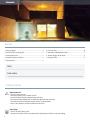
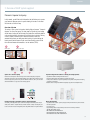
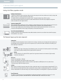
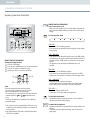
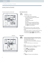
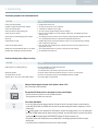
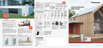
AQUAREA
USER GUIDE
for Bi-Bloc,
Monobloc &
All In One
WH-ADC_ _ _G_ _
WH-SDC_ _ _F_ _
WH-SXC_ _ _F_ _
WH-SHF_ _ _F_ _
WH-MDC_ _ _F_ _
WH-MHF_ _ _F_ _
AQUAREA USER GUIDE/ FOR BI-BLOC, MONOBLOC AND ALL IN ONE SYSTEMS 2014
Summary
1. Safety precautions ..............................................................................2
2. Overview of ASHP system supplied.......................................................3
3. Control panel function..........................................................................5
4. Operating Instructions of System..........................................................5
5. Troubleshooting....................................................................................9
6. Error Fault Codes................................................................................10
7. Maintenance Schedule/Regular Checks..............................................11
8. Technical Support Contact details ......................................................11
9. Recycling of Units .............................................................................11
Model
Serial number
1. Safety precautions
Indoor/outdoor unit
· Do not sit or step on the unit
· Do not place anything on top or beneath the units
· Do not insert fingers into unit, rotating parts may cause injury
· Do not touch the sharp aluminium fins on outdoor unit, sharps parts may cause injury
· Do not wash the indoor unit with water, benzene, thinners or scouring powder
· Service to units should be carried out by Qualified Personnel only.
Control Panel
· Do not let the control panel get wet,
· Do not press the buttons on the control panel with hard, pointed objects. Otherwise it may cause damage
2
USER GUIDE
2. Overview of ASHP system supplied
Panasonic Aquarea heat pump
In this manual, you will find useful information that will allow you to operate
your Panasonic Aquarea system to provide heating & hot water in the most
efficient and cost effective way.
Overview of System
The centre of your system is the market leading high performance “Panasonic
Aquarea” air source heat pump. This heat pump can provide all your heating
and hot water, heating will be delivered using underfloor, traditional radiators
or fan assisted radiators, Hot water will be supplied from a cylinder, Delivery
of heat is usually controlled by the Panasonic controller, which will
automatically operate your heat pump when heating is required during the
heating season and hot water all year round. Room heating control will be
from room wall mounted thermostats or on the radiators (TRV’s).
1b
2
1a
1c
Bi-Bloc option
3
4
New All in One option
1a
1b
1c
Aquarea air to water heat pumps
Panasonic has developed an extensive range of air-to-water heat pumps designed to
efficiently convert free air into sustainable heating and hot water. Fitted externally to your
home and designed to operate in all year round weather conditions (-20 ºC), it’s the smart
efficient alternative to oil, gas and electric heating systems.
3
Heating control App for smartphone, tablet or computer (Optional)
The heating control App allows you to control the heating and hot water system via your
smart phone, tablet or computer with ease, whether at home or away. The heat pump can
be also connected to house management system using KNX, Modbus or Zig Bee interfaces.
2
Aquarea Air. High efficient radiators for heating and cooling (Optional)
· High efficient radiators working with water at 35°C.
· N o need for two kits if both floor heating and radiators are required.
· A s the product is efficient, it opens the possibility to also provide cooling while still meeting
construction requirements.
Panasonic offers a cooling mode within its heat pump range for low consumption homes.
4
Water tanks (Optional)
· High efficient tank solution: specially designed to improve the efficiency of the domestic
hot water production .
· Low energy losses
· High exchange surface for high efficiency and short time to heat up the water.
· 180, 200, 300, & 400 L versions
· WH-TD20E3E5-UK / WH-TD30E3E5-UK
· PAW-TE18C2E3HI-UK / PAW-TE18C2E3STD-UK
· PAW-TE30C2E3STD-UK / PAW-TE40C2E3STD-UK
3
2. Overview of ASHP system supplied
Heating & Hot Water preparation in detail
Radiators (Panel Heaters)
To optimise the maximum efficiency and lowest flow rate from the heat pump to heat the room, radiators can be wider or deeper than
radiators you expect to see when connected to a boiler system.
For maximum efficiency and individual room temperature control, Thermostatic Radiator Valves (TRV’s) are fitted.
Most radiator thermostats will either have numbers or roman numerals marked on them when they are adjusted, the higher the
number, the warmer the room target set will be.
Underfloor Heating (UFH)
Where underfloor heating is installed you will see a manifold in a cupboard with pipes coming off them and going into the floor, these
pipes heat the floor and therefore the room, the room temperature will be controlled by a room thermostat connected.
Do not use a high insulated product in floor finishing as this will inhibit the heat being transferred from floor to air, and in turn
increase the flow temperature to achieve target air temperature, with increased running costs.
Fan Coil (fan Assisted Radiators)
Designed to operate at a lower flow temperatures than traditional radiators to heat the room and ideal to be used with heat pumps
where underfloor is not an option.
The Panasonic Aquarea system main components
Outdoor Unit
The outdoor unit extracts temperature from the air when the fan is turning to start the process of changing this low temperature to a
high temperature using a compression cycle, once the compression cycle is carried out the heat is transferred to the heating or hot
water depending on requirements.
Monobloc
Panasonic supply 2 types of heat pumps, firstly a Monobloc system, in this system the hot water produced to feed the heating
and hot water is produced externally from the property inside the outdoor unit.
Bi-Bloc
The other Panasonic unit is called a Bi-Bloc system this unit generates hot water from an internal unit (Hydro module)
connected to an outdoor unit.
All in one*
New All in One hydromodule + 200l tank
Panasonic has developed a highly efficient solution, easy to install.
Based on the Bi-Bloc system, you have an outdoor unit, with the Hydro Module and DHW Cylinder all in one cabinet indoors.
*Preliminary design. Significant changes may occur.
Cylinder
Where a system is installed to supply hot water their will be a cylinder with ready to use stored hot water at approximately 50°C, this
water is lower than you would expect from a boiler system but hotter than you require for washing/showering 39-44°C, more volume is
stored to compensate for less cold water mixing for use, therefore saving money on not heating water to a higher stored temperature.
Room Thermostat
This allows a simple adjustment to the room temperature, the higher the room target set the higher the running cost. It can be
supplied as an option by Panasonic (PAW-A2W-RTWIRED or PAW-A2W-RTWIRELESS) or another one can be used.
4
USER GUIDE
3. Control panel function
Panasonic Controller
The Controller is found as a separate unit internally installed for the Monobloc unit, on the Bi-Bloc system the controller is found on the internal Hydro module.
9
8
7
6
5
4
3
2
1
10
11
ACTUAL
AUTO
HEAT
COOL
TANK
HEATER
HEATER
MON TUE WED THU FRI SAT SUN
ON
OFF
FORCE
hr BOOSTER
°C
QUIET
kwh SETTING
hr STATUS
°C
SERVICE
OPERATION
12
13
14
15
16
17
18
19
No
Button assignment
17
Operation button (ON / OFF)
18
Operating mode selection button
Use this button to select the operating mode required.
19
System status buttons
These buttons are used for a series of status queries. Proceed as
follows:
· Press the CHECK button for 5 seconds to switch to Status mode.
· Press the UP or DOWN button to open the following values:
1. Compressor operating frequency
2. Error code
3. Water inlet temperature
4. Water tank temperature
· Press the CANCEL button or wait 30 seconds to quit Status
mode.
28 27 26 25 24 23 22 21 20
No Displays
Operation LED
20
Service button (Engineer use only)
2
Display of external room thermostat
21
3
Display if Solar (Hydro) active (if installed)
4
Indicator that back up heater is enabled ( ) or disabled
(nothing showing)
5
Hot-water tank operation display (ON / OFF)
6
Cooling operation display (ON/OFF), (if applicable)
B utton for enabling the additional electric heater for the heat
pump. The additional electric heater can only be used if this
button is pushed. Note: If this button is not pressed, the additional
electric heater for the heat pump is only used for:
· Defrosting
· Device startup
· Frost protection mode
7
Heating operation display (ON / OFF)
22
Holiday button
8
Auto Mode OFF/ON Indicator
This icon indicates auto mode OFF/ON operation.
23
Quiet mode button
24
9
Display of timer setting and time
S ystem programming buttons
These buttons are used to set temperature values.
25
E mergency heating mode button
This button allows the device to be operated in emergency heating
mode with the additional electric heater for the heat pump, e.g. if
the heat pump is defective.
Press the ON / OFF button to switch off emergency heating mode.
26
T imer programming buttons
These buttons are used to set the time and the weekly timer.
27
The system is turned off by an external switch.
28
Warning sign on display this is to say the following: Indicator
that DHW is stored at +60 ºC – WARNING “HOT”
1
10 Display of outside temperature
11 Display of Heat Pump water flow temperature
12 Indicator that back up heater for heat pump and electric immersion
heater for the hot water tank is operating (on/off)
13 Display for quiet mode (ON / OFF)
14 Display for system programming (ON / OFF)
15 Display for system status (ON / OFF)
16 Display for in service mode (Engineers use only)
* Note: As the same operator control panel is used for different devices, some functions may not apply for your device.
5
4. Operating Instructions of System
Operating Instructions (Controller)
REMOTE CONTROL PREPARATION
Press to turn unit on or off
· When unit is ON, operation LED is lit and the actual temperature for
water outlet and outdoor ambient are shown on the remote control
display.
ACTUAL
AUTO
HEAT
COOL
HEATER
MON TUE WED THU FRI SAT SUN
ON
TANK OFF
HEATER
FORCE
hr BOOSTER
°C
QUIET
kwh SETTING
hr STATUS
°C
SERVICE
To select operation mode
OPERATION
AUTO
AUTO + TANK
HEAT
HEAT + TANK
TANK
COOL + TANK
COOL
HEAT MODE
· To turn ON or OFF the heating operation.
· In this mode the heat pump will provide energy only for the Heating
of the property.
REMOTE CONTROL PREPARATION
Setting Current Day and Time
1
Press
the CLOCK button
2 Press the UP or DOWN button to set the current weekday
3 Press the SET button to confirm the setting
4 Repeat steps 2 and 3 to enter the current time
2
3
1
*Note
The current weekday and time must be set when:
· The power supply is switched on for the first time,
· After a long interruption to the power supply.
The current time set is the time basis for all timer functions
· In normal operation,
the , and buttons are not
in use.
· If cooling is activated then you may/will not be eligible for
government grants.
*1 The system is locked to operate without COOL mode. It can
be unlocked only by authorised installers or our authorised
service partners.
*2 Only displayed when COOL mode is unlocked (Means when
COOL mode is available).
6
HEAT + TANK MODE
· In this mode the heat pump will provide energy to the DHW cylinder
or the Heating or the property. (actual mode of operation will not be
indicated, and only if DHW cylinder is connected to the heat pump
control)
· This operation is not used when the DHW water tank is not
installed.
TANK MODE
· To turn ON or OFF the DHW tank operation.
· In this mode the heat pump will provide energy only to the DHW
cylinder) only if the cylinder is connected to the heat pump control).
COOL + TANK MODE (*1, *2)
· Heat pump provides cooling to the property
· The heat pump controls the booster heater in the DHW cylinder
(only if DHW cylinder is connected to the heat pump control)
COOL MODE (*1, *2)
· The panel is either turned ON or OFF.
· To turn ON or OFF the heat pump cooling operation
To enjoy quiet environment
· This operation reduces heat pump unit noise. In this condition, it
may cause decrease in heating capacity.
To enable the backup heater
· The backup heater will only operate when the setting conditions are
fulfilled.
· To disabled the Heater operation manually, press the respective
button again.
USER GUIDE
Operating Instructions (Controller)
Heating & Domestic Hot Water Operating Times Set Up
NOTE: This timer is not like normal timers you may have operated before, the Panasonic timer
works on the basis of last command stands, once you start a command this will stand unless
you ask for another command to operate/commence or switch the command “OFF”
ACTUAL
AUTO
HEAT
COOL
HEATER
hr BOOSTER
MON TUE WED THU FRI SAT SUN
°C
ON
TANK OFF
QUIET
kwh SETTING
hr STATUS
HEATER
°C
FORCE
SERVICE
Panasonic would recommend that you set you DHW preparation for 24/7 (standing heat loss on
new cylinders is negligible).
It can also be advantageous to set your heating system to be active 24/7 during the heating
demand season- consult your installer for the most efficient set up given your design and
requirements.
OPERATION
Indicates the sele
Lights up if Timer operation is selected
6 different programs can be set in a select day (1 ~ 6)
TIMER
1 2 3 4 5 6
MON TUE WED THU FRI SAT SUN
C
ON
OFF
SOLAR
REMOTE
Water temperature thermo shift (-5ºC ~ 5ºC)
OFF Timer - To automatically switch “OFF” the
ON Timer - To automatically switch “ON” the unit
Day to be selectedunit
STATUS
SETTING
TIMER
SET
MODE
OFF/ON
SELECT
QUIET
CLOCK
CANCEL
HEATER
Setting the weekly timer for operation of heat / tank to be activated
To enter the Timer mode
1. P ress the TIMER button.
Setting the date and time for operation to be activated
2. Press the UP or DOWN button to select your desired day.
3. P ress the SELECT button to confirm.
“1” will be blinking.
4. Press the SELECT button to set Program 1.
5. Press the OFF/ON button to select ON or OFF timer.
6. Press the UP or DOWN button to select your desired time.*
7. Press MODE to select operation to be carried out
AUTO
HEAT
HEAT + TANK
TANK
COOL **
If HEAT or HEAT + TANK is selected you are able to change the shift temperature with the UP
or DOWN bottom.
Press the SET button to confirm Program 1.
The selected day is identified with the symbol.
After 2 seconds, the display will move to the next program.
8. R epeat the steps 4 to 7, starting with the OFF/ON button, to set additional commands 2 to 6
(if required).
9. If no buttons are pressed for 30 seconds during timer setting, or if you press the SET button,
the current setting is saved and the timer setup is ended.
*In step 6 you can also activate QUIET or HEATER by pressing such bottoms in the remote
instead of the MODE one and following the same procedure
** If cooling is activated then you may/will not be eligible for government grants.
7
4. Operating Instructions of System
Operating Instructions (Controller)
The system is turned off by an external switch.
System status check mode
1. P ress check.
(The display shows STATUS.)
2. P ress UP or DOWN to check the selected mode.
· Dry concrete (does not show during normal operation)
· The Water Inlet Temperature
· Tank Temperature
· Compressor Running Frequency
· Error History
· Heat mode total power consumption (Up to 999 days)
· Cool mode*1 total power consumption (Up to 999 days)
· Tank mode total power consumption (Up to 999 days)
· Press
to exit the STATUS mode.
*Note
Once the STATUS mode is entered, the display shows STATUS.
· The STATUS mode cannot be activated when the display shows
SETTING.
· T he total power consumption is an estimated value based on AC 230
V and may differ from value measured by precise equipment.
· In normal operation,
the , and buttons are not in use.
Desired days
Holiday mode
· B y setting the day (s) in holiday mode, it promotes energy saving
while you are on holiday, and enables the system to resume at the
preset temperature after your holiday.
· Ensure that the system is OFF before setting.
· T he system will resume operation automatically at 00:00 am after
the holiday.
· The day the HOLIDAY mode was set is counted as day 1.
Example:
Setting the holiday mode on June 21, 08:00 am. By setting 3 days,
the system resumes operation on June 24, 00:00 am.
1. Press
to enter the HOLIDAY mode.
2. P ress UP or DOWN to set the desired days.
(Setting range: 1 day ~ 999 days)
3. Press to confirm the setting.
* Note
Press
8
or wait 30 seconds to exit the HOLIDAY mode.
USER GUIDE
5. Troubleshooting
The following symptoms do not indicate malfunction.
SYMPTOM
CAUSE
Flowing sound during operation.
Operation is delayed a few minutes after restarting.
Outdoor unit emits water/mist.
Outdoor unit emits mist during heating mode.
Outdoor unit does not operate.
(Outdoor unit) Air-to-water Heatpump system operation
will turn off.
System difficult to heat-up.
System cannot get warm instantly.
Backup heater turn ON automatically when it is not enabled.
Operation starts automatically even without ON Timer.
Refrigerant flow inside the unit.
The delay is a protection to the unit’s compressor.
Condensation or evaporation occurs on pipes
This is due to defrost operation happens at the heat exchanger.
When the outdoor temperature is out of the operation condition range, the heatpump system enter
protection control.
The heatpump system enter protection control. Compressor stops by water inlet temperature lower than
18°C; and backup heater power turn on by water inlet temperature lower than 23°C.
Multiple heating circuits can effect the performance at times. Is the snow pile blocking the discharge
outlet or intake inlet of outdoor unit.
Due to the nature of the heatpump system, it may take some time to heat-up the water if the unit is
operated from cold-start.
The turn ON of backup heater is a protection to the indoor unit’s heat exchanger.
The sterilisation timer has been set.
Check the following before calling for servicing .
SYMPTOM
CAUSE
Heating operation is not working efficiently.
Noisy during operation.
The outdoor unit does not work
Operation LED is no lit or remote control display is blank.
Check the temperature set on house/room thermostat
Is the radiator valve (TRV closed)
Clear any obstructions of the air inlet or outlet vents of the outdoor unit
Check if the outdoor unit has been installed at an incline or a cover is not closed properly.
Check if the circuit breaker on house electrical distribution board has not tripped.
Is the power supply off or power failure.
Indicator that the domestic hot water in the cylinder is above +60 ºC
(only if controlled by A2W heat pump)
TIMER
TIMER
1 2 3 4 5 6
MON TUE WED THU FRI SAT SUN
ON
OFF
FORCE
The operation LED blinks and error code appear on remote control display.
· Turn the unit off and reveal the error code to authorised dealer.
· Timer operation cancel when error code occur.
Force Heater Mode Button
· In case of a failure of the heat pump system but still power to the unit, the electric heaters can be activated to
provide HEAT, HEAT+TANK or just TANK, check the mode of operation showing (check what is displayed on 6 & 8 on
control panel)
· If a showing against 6 or 8, then when the FORCE button is pressed this will be activated, if it is not showing then
press then the MODE button until the required setting is displayed, once the FORCE button is pressed to activate the
operation the will disappear against HEATER BOOSTER (display 12) and the operation is set.
· Using FORCE heater mode, all operations are not allowed (this is an emergency operation and will incur higher
running costs)
· Press (insert picture of on/off button) to stop the Force heater operation.
9
6. Error Fault Codes
ERROR CODE
Error/Protection triggered
F12
F14
F15
Pressure switch triggered
Compressor abnormal
Incorrect speed of the outdoor unit fan
F16
F20
F22
F23
F24
F25
F27
F36
F37
F40
F41
F42
F43
F45
F46
F95
H12
H15
H20
H23
H42
H62 *
Protection against excessive total operating current
Compressor overheating guard
Power transistor module overheating guard
Direct current peaks in the outdoor unit
Problems in the cooling circuit
Problem switching between heating and cooling
Pressure switch
Outside temperature sensor
Return temperature sensor in indoor unit
Hot gas temperature sensor in the outdoor unit
PFC circuit
Temperature sensor of the heat exchanger in the outdoor unit
Outdoor unit defrosting temperature sensor
Supply temperature sensor in indoor unit
Current converter open in outdoor unit
Cooling high pressure guard in outdoor unit
Unsuitable output between the indoor and outdoor unit
Compressor temperature sensor
Water pump abnormal
Liquid temperature sensor
Compressor low pressure
Water-side flow rate cut-out
H64
H65
H70 *
High-pressure sensor
Defrost circulation error
OLP additional electric heater for heat pump
H72
H76 *
Hot water tank temperature sensor
Communication error between remote and HP
H90
Communication errors between indoor and outdoor unit
H91 *
OLP electric immersion heater for hot-water tank
H95
H98
H99
Indoor/outdoor unit incorrectly connected
High pressure guard in outdoor unit
Antifreeze protection for indoor unit heat exchanger
Indicator ONLY - DHW is stored at above +60 ºC –
“WARNING HOT”
* Errors experienced following initial installation.
10
RECOMMENDATIONS
Contact your local Panasonic installer, quoting fault code
Contact your local Panasonic installer, quoting fault code
Check there are NO obstruction of FAN in outdoor unit (leaves, sticks or snow). Switch
off power before attempting to remove any obstruction. Fans can start without warning.
Contact your local Panasonic installer, quoting fault code
Contact your local Panasonic installer, quoting fault code
Contact your local Panasonic installer, quoting fault code
Contact your local Panasonic installer, quoting fault code
Contact your local Panasonic installer, quoting fault code
Contact your local Panasonic installer, quoting fault code
Contact your local Panasonic installer, quoting fault code
Contact your local Panasonic installer, quoting fault code
Contact your local Panasonic installer, quoting fault code
Contact your local Panasonic installer, quoting fault code
Contact your local Panasonic installer, quoting fault code
Contact your local Panasonic installer, quoting fault code
Contact your local Panasonic installer, quoting fault code
Contact your local Panasonic installer, quoting fault code
Contact your local Panasonic installer, quoting fault code
Contact your local Panasonic installer, quoting fault code
Contact your local Panasonic installer, quoting fault code
Contact your local Panasonic installer, quoting fault code
Reset once if reoccurring contact your local Panasonic installer, quoting fault code
Contact your local Panasonic installer, quoting fault code
Contact your local Panasonic installer, quoting fault code
Check & Clean in line filter. Remove air within the pipework. Reset the system. If
fault occurs repeatedly (4 or more times in 24hrs) contact your local Panasonic
installer quoting fault code.
Contact your local Panasonic installer, quoting fault code
Reset once if reoccurring contact your local Panasonic installer, quoting fault code
This error code can be reset via controller. System will appear to be running normally.
You must contact your local Panasonic installer, quoting fault code for a full reset.
Contact your local Panasonic installer, quoting fault code
Reset error. Switch off (power) for 2 minutes. Wait 1 minute. If still present contact
your local Panasonic installer, quoting fault code
Reset error. Ensure all isolators are switched on. Contact your local Panasonic
installer, quoting fault code
Check thermostat on cylinder is not set too high. Reset error. If reoccurring contact
your local Panasonic installer quoting fault code.
Contact your local Panasonic installer, quoting fault code
Contact your local Panasonic installer, quoting fault code
Contact your local Panasonic installer, quoting fault code
No action required
USER GUIDE
7. Maintenance Schedule/Regular Checks
Regular Checks
Maintenance Schedule
· Periodic inspection of indoor/outdoor units and connections.
· Ensure outdoor unit NEVER has obstacles covering the unit,
especially in Autumn with leaves and Winter with snow.
An annual maintenance/service contract is recommended to
ensure optimum performance from your Panasonic A2W Heat
Pump, please contact an accredited Panasonic installer for more
details.
8. Technical Support Contact details
Please call your installer as the first point of call, indicating the fault or fault code,
otherwise please call Panasonic Technical Support 01344 853 303 for assistance.
(Your warranty card details will be required)
9. Recycling of Units
After the end of the product’s service life, it must be disposed of appropriately.
The respective environmental protections regulations must be observed at the time of disposal.
11
www.eggeassociats.net
Due to the ongoing innovation of our products, the specifications of this catalogue are valid barring typographic errors, and may be subject to minor modifications by the manufacturer
without prior warning in order to improve the product. The total or partial reproduction of this catalogue is prohibited without the express authorisation of Panasonic UK Ltd.
Do not add or replace refrigerant other than the specified
type. Manufacturer is not responsible for the damage and
deterioration in safety due to usage of the other refrigerant.
To find out how Panasonic cares for you,
log on to: www.aircon.panasonic.co.uk
Contact Details:
Telephone: 01344 853182
[email protected]
Address: Panasonic Air Conditioning
Panasonic House
Willoughby Road
Bracknell
Berkshire
RG12 8FP