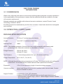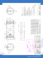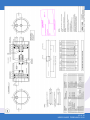
1
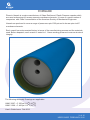
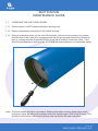
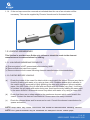
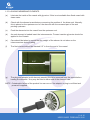
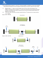
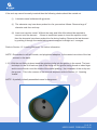
User’s Guide
3
to:
Phoenix Vessel Technology Limited
350/400 psi End port pressure vessels 4”.
Phoenix Vessel Technology Limited
T: +44 (0) 1452 311673
F: +44 (0) 1452 310295
Model number: 3307, 1209.
Unit 2, The Old Bakery, Lower Tuffley Lane, Gloucester GL2 5DP
E: [email protected]
www.phoenixvessel.co.uk
TABLE OF CONTENTS
FORWARD
SECTION 1 ‘Maintenance Guide’
1.1 Removing End Cap from Vessel
1.2 Loading Membranes
1.3 Closing Vessel
3
4
4
5
8
SECTION 2 ‘Installation’
2.1 Handling
2.2 Vessel Support Position
2.3 Connections to Vessel
10
10
11
11
SECTION 3 ‘Operation’
3.1 Corrosion
3.2 Operating Conditions
3.3 Safety Precautions
12
12
12
13
SECTION 4 ‘Appendix’
4.1 Spare Parts List
4.2 Assembly Drawing 3307
4.3 Assembly Drawing 1209
13
13
14
15
2 of 15
USER GUIDE FEBRUARY 2012
FORWARD
Phoenix Vessels is a major manufacturer of Glass Reinforced Plastic Pressure vessels which
are used as housings for reverse osmosis membrane elements. It is one of a small number of
companies with Code X accreditation of the American Society of Mechanical Engineers.
Vessels are produced to cover a range of pressures upto 1000 psi and to house upto six 40”
membrane elements.
Each vessel has a documented history in terms of the manufacturing process and the materials
used. Before despatch, each vessel is tested to 1.1 times working pressure to ensure structural
integrity.
The following Assembly Drawings are applicable:
1MNC 3307 - 4” 350 psi 113oF (45oC)
1MNC 1209 - 4” 400 psi 113oF (45oC)
User’s Guide Issue: Feb 2012
3 of 15
USER GUIDE FEBRUARY 2012
SECTION ONE
MAINTENANCE GUIDE
1.1
REMOVING END CAP FROM VESSEL
1.1.1 Ensure system is NOT pressurised before starting work.
1.1.2. Remove all pipework connected to the vessel end cap.
1.1.3. Using a screwdriver lever out the end of the spiroloc circlip from the groove in the vessel.
Hold the end of the circlip from springing back into the groove and remove the remaining
part by running an index finger behind the circlip with a rotating movement. Note : If the
end of the screwdriver is bent over by 15 -30 degrees then extraction is considerably easier.
Note: Any loose debris should be removed by flushing with water and any sharp edges made
smooth by lightly abrading with waterproof silicone carbide paper (200 Grade or finer). This
should be done before removing the plastic end cap as this will ease extraction.
4 of 15
USER GUIDE FEBRUARY 2012
1.1.4 If the end cap cannot be removed as indicated then the use of an extractor will be
necessary. This can be supplied by Phoenix Vessels and is illustrated below.
1.2 LOADING MEMBRANES
This Section is provided as a Guide only, reference should be made to the element
manufacturers recommendations for loading.
1.2.1 UNLOADING MEMBRANE ELEMENTS
(a) Ensure system is NOT pressurised before starting work.
(b) Remove both end caps from vessel.
(c) Remove element from vessel following element manufacturers recommendations.
1.2.2 CHECKS BEFORE LOADING
(a)
Check the inside of the vessel for debris which may scratch the vessel. Remove any that is
found by flushing with water or by using a clean cloth. Stubborn debris which adheres to
the vessel may be removed by lightly polishing the area with waterproof silicone carbide
paper. Use 400 Grade (fine) to start with and finish with 600 Grade (very fine). It will help
to moisten the grit paper with water during use. Avoid continuously rubbing the same spot
in the same direction. Afterwards remove any debris with water or by using a clean cloth.
(b)
Check that there are no sharp edges to the membrane element which could scratch the
vessel. Contact the element manufacturer if these cannot be easily removed.
(c)
Check the element brine seal for wear and or cuts. Consult the element manufacturer for
spares and advice.
NOTE: Sharp debris may scratch vessel bore. This should be removed before unloading elements.
NOTE: Fine grade Scotchbrite may be substituted for waterproof silicone carbide paper.
5 of 15
USER GUIDE FEBRUARY 2012
1.2.3 LOADING MEMBRANE ELEMENTS
(a)
Lubricate the inside of the vessel with glycerine. If this is not available then flood vessel with
clean water.
(b)
Check with the element manufacturer concerning the position of the brine seal. Normally
this is placed on the upstream end of the element with the recessed part of the seal
pointing upstream.
(c) Push the elements into the vessel from the upstream end.
(d)
As each element is loaded insert the interconnector. To ease insertion glycerine should be
applied to the O-seals.
(e) Care should be taken to ensure that the weight of the element is not taken on the
interconnectors during loading.
(f) The final element should be inserted 2.5” in from the end of the vessel.
2.25”
(g) The plug and adaptor (multi element vessels) should be removed from the vessel before
loading the elements - they may be fitted to either end of the element train.
NOTE : Catastrophic failure of the product line can occur if the adaptor or plug is not fitted and
pressure is applied.
6 of 15
USER GUIDE FEBRUARY 2012
(h) For single element vessels (i.e. upto 40” of element length) no adaptors or shims are supplied.
Multi-element vessels fall into two categories depending on the type of element in the vessel:
(1) Spigotted type - i.e. has a core tube which is proud of the face of the element. One
adaptor and three shims are supplied. The shims are required to ensure that the element
remains connected to the pressure vessel end cap, these should be placed between the
adaptor and the end cap.
(2) Flush fitting (also referred to as close coupled) element. This type does not require shims
or an adaptor.
Model: 3307 - 350 PSI
Single element
Multi element
(2 - 6 elements)
shim
(3 max)
interconnector
(not supplied)
Model: 1209 - 400 PSI
Single element
plug
hub
Multi element
(2 - 6 elements)
plug
interconnector
(not supplied)
shim
(3 max)
hub
adaptor
7 of 15
USER GUIDE FEBRUARY 2012
The required number of shims may vary between any two vessels loaded with elements due to
tolerance build up, each will require measuring to find the exact number required. There are two
ways to do this :
Method 1 - Work out the end float from element to vessel by measuring the distance from the
face of the element to the groove and subtracting the end fitting thickness. Each shim
has a thickness of 10mm, aim to obtain an end float of 2 to 12mm. Thus if the endfloat is
1mm, remove a shim. If it is 13mm, add a shim. A maximum of 3 shims may be fitted.
Method 2 - Fit the maximum number of shims to the adaptor, each has thickness of 10mm and
a maximum of 3 maybe fitted to the upstream adaptor. Fit the adaptor onto the core tube
of the element. Then remove the large 4” diameter seal from the end fitting so that no
resistance will be required to push it into the vessel. Push the end fitting into the
vessel until it will go no further. If the full width of the groove in the vessel is visible then
the correct number of shims have been fitted. If not, then remove one shim and repeat
the above procedure until the groove is visible. Remember to refit the large O-seal.
1.3 CLOSING VESSEL
1.3.1. Thoroughly clean all parts and check for the following.
(a) O-SEALS - cracked, worn or cut areas.
(b) END CAP - cracks between ports, distorted or bearing edges worn.
(c) CIRCLIP - Corroded or badly distorted.
Components which show any of the above should be replaced.
NOTE : It is recommended that O-seals are replaced every time the end cap is rebuilt.
1.3.2. Check the inside of the vessel for debris which may scratch the vessel. Remove any that is
found by flushing with water or by using a clean cloth. Stubborn debris which adheres to
the vessel may be removed by lightly polishing the area with waterproof silicone carbide
paper Use 400 Grade (fine) to start with and finish with 600 Grade (very fine). It will help
to moisten the grit paper with water during use. Avoid continuously rubbing the same spot
in the same direction. Afterwards remove any debris with water or by using a clean cloth.
NOTE : Fine grade Scotchbrite may be substituted for water- proof silicone carbide paper.
3. Lubricate the vessel inside surfaces with glycerine.
4. Lubricate the assembled end cap with glycerine, particularly the large 4”
diameter O-seal.
5. Insert the end cap squarely into the vessel body sufficient to allow the spiroloc
circlip to be inserted fully into the groove in the end of the vessel. If the end fitting
is difficult to push into the vessel then use the wooden shaft of a hammer to tap it
into position.
NOTE : Under no circumstances should undue force be used to insert the end cap. A light tap is
all that is required.
8 of 15
USER GUIDE FEBRUARY 2012
If the end cap cannot be easily inserted then the following checks should be carried out.
(i)
Lubricate vessel surfaces with glycerine.
(ii) The elements may have been pushed too far, proceed as follows: Remove large 4”
diameter seal from end cap.
(iii) Insert end cap into vessel. Without the main seal little effort should be required to
connect onto the element. If there is insufficient space to insert the spiroloc circlip
then the elements have been pushed too far during loading. Remove the last element
by pushing it through the vessel taking care to support its weight as it emerges.
Refer to Section 1.2 ‘Loading Elements’ for further information.
NOTE : Remember to refit all O-seals, and plugs/solid adaptors to the central core tube of the last
element in the stack.
1.3.3. With the end fitting in place insert the spiroloc circlip into the groove in the vessel. The best
technique to use is to lead one end of the circlip into the groove using thumb or index finger
and to move thumb round the inside of the vessel pushing the remainder of the circlip into
the groove . This is the reverse of the removal sequence refer to Section 1.1 ‘Opening
Vessel’.
NOTE : A partially or badly assembled vessel is dangerous.
9 of 15
USER GUIDE FEBRUARY 2012
SECTION TWO
INSTALLATION
2.1
HANDLING
2.1.1 Vessels may be stored horizontally in any warehouse where the temperatures are as
follows:
Maximum 45o C (113o F)
Minimum 0o C ( 32o F)
2.1.2 DO NOT subject the vessel to sharp blows or impacts as this may damage the vessel wall.
2.1.3 DO NOT use the ports which project beyond the vessel as lifting or manoeuvring aids.
2.1.4 DO NOT scratch the vessel inside wall.
VESSEL DAMAGE
This should be reported to the shipping company upon receipt.
Contact Phoenix Vessels for advice if in doubt.
10 of 15
USER GUIDE FEBRUARY 2012
2.2 VESSEL SUPPORT POSITION
The bending stresses generated in a long pressure vessel can be considerable and should not be
ignored. Careful choice of support position can minimise bending stresses to an acceptably low
level. Always follow instructions stated on the Assembly Drawing for each particular vessel design
and length ordered.
The following is the recommended support positions for 2.5” vessels.
No. of 40’’
Elements
No. of
Supports
1
2
2
3
4
3
4
5
6
2
2
2
3
3
3
3
Distance between
Supports (mm)
Max
Min
800
200
1810
2270
2660
Distance between
Outer Supports (mm)
Max
Min
620
1640
2660
2830
3920
4250
4650
1640
2660
3670
4650
2.3 CONNECTIONS TO VESSEL
2.3.1 Mount vessels using support saddles provided on horizontal surface at the recommended
support position and tighten straps to eliminate movement, do not tighten to more than
drawing recommended torque.
NOTE : Excessive torque applied to the straps may damage the vessel wall.
2.3.2. Provide pressure relief device. This should be set to no more than 105% of design pressure.
2.3.3. Allow for an expansion of 0.5mm per metre length of vessel at design pressure.
2.3.4. Connections to end cap are ½” BSPT female thread for the feed and reject ports and 3/8”
BSPT female for the product line. The maximum torque applied to the threaded connections
should Be as stated in the table below. Note that when the vessel is working in an
environment which is hotter than the assembly temperature the thread torque reduces.
Similarly as the temperature reduces the assembly torque increases. This is due to thermal
expansion of the thermoplastic end cap. Obviously a lightly torqued fitting may leak at high
temperature and so recommended torque figures should be followed. If a pre-set torque
wrench is used to tighten the fitting into the end cap make sure that at least three ‘clicks’ are
heard i.e. that the torque level is checked at least three times. Often some additional
movement is obtained at the second and third attempts.
11 of 15
USER GUIDE FEBRUARY 2012
3.1 CORROSION
SECTION THREE
OPERATION
Whilst every effort has been taken to ensure that end fittings have adequate corrosion resistance it
is the responsibility of the purchaser to assess that the materials offered are suitable for the specific corrosion environment.
Alternate materials are available with enhanced corrosion resistance, contact Phoenix Vessel
Technology Limited for advice.
End fittings should be maintained dry and free from corrosion. Vessel leaks should be investigated
and corrected.
3.2 OPERATING CONDITIONS
DESIGN SPECIFICATION
Internal Diameter:
To fit any 4” nominal diameter element.
Length:
Up to 240” of membrane elements.
Working Fluid:
Water
NOTE : The standard materials of construction may not be compatible with cleaning and
preserving fluids. Alternative materials are available on request.
Design Pressure:
350 psi (24.2 bar).
400 psi (27.6 bar).
Test Pressure:
1.1 times design pressure for upto 15 minutes maximum.
Design Temperature:
20 to 113o F (-7 to 45o C).
NOTE : Although the minimum design temperature is 20 deg F the vessel should not be allowed to
freeze solid. This will damage the vessel wall and make replacement necessary.
Expansion:
0.5 to 0.6 mm per metre length of vessel at design pressure.
Vacuum condition:
Vessel end fittings will move out of position under vacuum loads. Contact
Phoenix Vessels for advice.
Support Position:
2 supports for 1 to 4 (40”) elements.
3 supports for 5,6 (40”) elements and any length supported outside of recommended support range ( refer to `Vessel Support Position’ Section
2.2 of User’s Guide).
12 of 15
USER GUIDE FEBRUARY 2012
3.3 SAFETY PRECAUTIONS
Fibreglass reinforced pressure vessels will provide years of safe service if properly installed and
maintained. This section is for guidance only and should be used in conjunction with the
recommendations in the previous sections. Attention is drawn to the `NOTES:` located at the bottom of the page which highlight potential problems areas and safety recommendations.
3.3.1 Provide pressure relief device. This should be set to no more than 105% of design pressure.
3.3.2 Before pressurisation visually check that the 3 part retaining ring is fully in position and
secured by the two cap head screws.
3.3.3 DO NOT stand in line of end fitting while pressurisation takes place.
SECTION FOUR
APPENDIX
4.1 SPARE PARTS LIST
For part numbers and descriptions please refer to the relevant Technical Information Sheet.
13 of 15
USER GUIDE FEBRUARY 2012
14 of 15
USER GUIDE FEBRUARY 2012
15 of 15
USER GUIDE FEBRUARY 2012