1
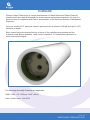
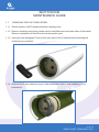
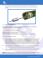
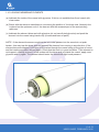
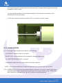
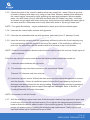
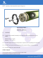
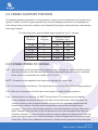
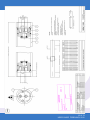
User’s Guide
1
to:
Phoenix Vessel Technology Limited
1000 psi End port pressure vessels 2.5”.
Phoenix Vessel Technology Limited
T: +44 (0) 1452 311673
F: +44 (0) 1452 310295
Model number: 1503
Unit 2, The Old Bakery, Lower Tuffley Lane, Gloucester GL2 5DP
E: [email protected]
www.phoenixvessel.co.uk
TABLE OF CONTENTS
FORWARD
SECTION 1 ‘Maintenance Guide’
1.1 Removing End Cap from Vessel
1.4 Loading Membranes
1.5 Closing Vessel
3
4
4
5
7
SECTION 2 ‘Installation’
2.1 Handling
2.2 Vessel Support Position
2.3 Connections to Vessel
9
9
10
10
SECTION 3 ‘Operation’
3.1 Corrosion
3.2 Operating Conditions
3.3 Safety Precautions
11
11
11
12
SECTION 4 ‘Appendix’
4.1 Spare Parts List
4.2 Assembly Drawing 1503
12
12
13
2 of 13
USER GUIDE FEBRUARY 2012
FORWARD
Phoenix Vessel Technology is a major manufacturer of Glass Reinforced Plastic Pressure
Vessels which are used as housings for reverse osmosis membrane elements. It is one of a
small number of companies with Code X accreditation of the American Society of Mechanical
Engineers.
Only one model of 2.5” pressure vessel is produced, this is rated at 1000 psi and upto 2 (40”)
elements in length.
Each vessel has a documented history in terms of the manufacturing process and the
materials used. Before despatch, each vessel is tested to 1.1 times working pressure to
ensure structural integrity.
The following Assembly Drawings are applicable:
1MNC 1503 - 2.5” 1000 psi 113oF (45oC)
User’s Guide Issue: Feb 2012
3 of 13
USER GUIDE FEBRUARY 2012
SECTION ONE
MAINTENANCE GUIDE
1.1
REMOVING END CAP FROM VESSEL
1.1.1 Ensure system is NOT pressurised before starting work.
1.1.2. Remove couplings connecting vessel ports to manifolds and move them clear of the vessel. Remove connections if fitted from the central product port.
1.1.3. Using an 5mm hexagonal T bar or Allen key remove the 2 caphead screws holding the
retaining ring in position.
1.1.4 Remove the 3 part retaining ring set. Each piece has a slot or hole enabling it to be
levered out
4 of 13
USER GUIDE FEBRUARY 2012
1.1.5 If the end cap cannot be removed as indicated then the use of an extractor will be
necessary. This is of the sliding impact hammer type and can be supplied by Phoenix
Vessels.
1.4 LOADING MEMBRANES
This Section is provided as a Guide only, reference should be made to the element
manufacturers recommendations for loading.
1.4.1 UNLOADING MEMBRANE ELEMENTS
(a) Ensure system is NOT pressurised before starting work.
(b) Remove both end caps from vessel.
(c) Remove element from vessel following element manufacturers recommendations.
1.4.2 CHECKS BEFORE LOADING
(a)
Check the inside of the vessel for debris which may scratch the vessel. Remove any that is
found by flushing with water or by using a clean cloth. Stubborn debris which adheres to
the vessel may be removed by lightly polishing the area with waterproof silicone carbide
paper. Use 400 Grade (fine) to start with and finish with 600 Grade (very fine). It will help
to moisten the grit paper with water during use. Avoid continuously rubbing the same spot
in the same direction. Afterwards remove any debris with water or by using a clean cloth.
(b)
Check that there are no sharp edges to the membrane element which could scratch the
vessel. Contact the element manufacturer if these cannot be easily removed.
(c)
Check the element brine seal for wear and or cuts. Consult the element manufacturer for
spares and advice.
NOTE: Sharp debris may scratch vessel bore. This should be removed before unloading elements.
NOTE: Fine grade Scotchbrite may be substituted for waterproof silicone carbide paper.
5 of 13
USER GUIDE FEBRUARY 2012
1.4.3 LOADING MEMBRANE ELEMENTS
(a) Lubricate the inside of the vessel with glycerine. If this is not available then flood vessel with
clean water.
(b) Check with the element manufacturer concerning the position of the brine seal. Normally this
is placed on the upstream end of the element with the recessed part of the seal pointing
upstream.
(c) Lubricate the element brine seal with glycerine (do not use diluted glycerine) and push the element into the vessel using hands only (thumbs and base of palm).
NOTE : If the element becomes caught as the brine seal passes into the vessel do not push
harder - this may trap the brine seal and prevent the element from moving in any direction. If the
element becomes trapped it will have to be pushed through the vessel using a long piece of wood
and the loading procedure started again. Check that the seal is in good condition. If the element is
not trapped, carefully remove it a few inches until the brine seal is outside the vessel, apply more
glycerine and try again. The element should enter the vessel with light hand pressure.
6 of 13
USER GUIDE FEBRUARY 2012
(d) As each element is loaded insert the interconnector. To ease insertion glycerine should
be applied to the O-seals.
(e) Care should be taken to ensure that the weight of the element is not taken on the
interconnectors during loading.
(f) The final element should be inserted 2.25” in from the end of the vessel.
2.25”
1.5 CLOSING VESSEL
1.5.1. Thoroughly clean all parts and check for the following.
(a) O-SEALS - cracked, worn or cut areas.
(b) END CAP - cracks between ports, distorted or bearing edges worn.
(c) 3 PART RETAINING RING - corroded.
Components which show any of the above should be replaced.
NOTE : It is recommended that O-seals are replaced every time the end cap is rebuilt.
1.5.2. CORROSION - Examine metal components for evidence of corrosion which might affect
structural performance. Particularly pay attention to the 3 part retaining ring. Components
which cannot be restored to the ‘as new’ condition should be replaced.
7 of 13
USER GUIDE FEBRUARY 2012
1.5.3. Check the inside of the vessel for debris which may scratch the vessel. Remove any that
is found by flushing with water or by using a clean cloth. Stubborn debris which adheres to
the vessel may be removed by lightly polishing the area with waterproof silicone carbide
paper. Use 400 Grade (fine) to start with and finish with 600 Grade (very fine). It will help
to moisten the grit paper with water during use. Avoid continuously rubbing the same spot in
the same direction. Afterwards remove any debris with water or by using a clean cloth.
NOTE : Fine grade Scotchbrite may be substituted for water-proof silicone carbide paper.
1.5.4. Lubricate the vessel inside surfaces with glycerine.
1.5.5. Lubricate the assembled end cap with glycerine, particularly the 2.5” diameter O-seal.
1.5.6. Insert the end cap squarely into the vessel body sufficient to allow the 3 part retaining ring
to be inserted fully into the groove in the end of the vessel. If the end fitting is difficult to
push into the vessel then use the wooden shaft of a hammer to tap it into position.
NOTE : Under no circumstances should undue force be used to insert the end cap. A light tap is all
that is required.
If the end cap cannot be easily inserted then the following checks should be carried out.
(i)
Lubricate vessel surfaces with glycerine.
(ii) The elements may have been pushed too far, proceed as follows:
Remove 2.5” diameter seal from end cap.
(iii) Insert end cap into vessel. Without the main seal little effort should be required to connect
onto the element. If there is insufficient space to insert the 3 part retaining ring then the
elements have been pushed too far during loading. Remove the last element by pushing it
through the vessel taking care to support its weight as it emerges. Refer to Section 1.2
`Loading Elements’ for further information.
NOTE : Remember to refit all O-seals.
1.5.7. With the end fitting in place insert one of the three part retaining ring segments in place and
fix with one of the two M6 cap head screws. Do no tighten the caphead screw but leave
loose as this will make for easier location of the remaining pieces. Put both of the remaining
pieces into position before inserting the remaining cap head screws. Finally tighten both
cap head screws up to a maximum torque of 3Nm.
8 of 13
USER GUIDE FEBRUARY 2012
NOTE : A partially or badly assembled vessel is dangerous.
SECTION TWO
INSTALLATION
2.1
HANDLING
2.1.1 Vessels may be stored horizontally in any warehouse where the temperatures are as
follows:
Maximum 45o C (113o F)
Minimum 0o C ( 32o F)
2.1.2 DO NOT subject the vessel to sharp blows or impacts as this may damage the vessel wall.
2.1.3 DO NOT use the ports which project beyond the vessel as lifting or manoeuvring aids.
2.1.4 DO NOT scratch the vessel inside wall.
VESSEL DAMAGE
This should be reported to the shipping company upon receipt.
Contact Phoenix Vessels for advice if in doubt.
9 of 13
USER GUIDE FEBRUARY 2012
2.2 VESSEL SUPPORT POSITION
The bending stresses generated in a long pressure vessel can be considerable and should not be
ignored. Careful choice of support position can minimise bending stresses to an acceptably low
level. Always follow instructions stated on the Assembly Drawing for each particular vessel design
and length ordered.
The following is the recommended support positions for 2.5” vessels.
No. of 40’’
Elements
No. of
Supports
1 x 14”
2
Distance between
Supports (mm)
Max
Min
370
100
1 x 21”
2 x 14”
1 x 40”
2 x 21”
2 x 40”
2
2
2
2
2
550
700
1000
1050
1500
200
300
400
450
860
2.3 CONNECTIONS TO VESSEL
2.3.1 Mount vessels at the recommended support position. If straps are used to hold the vessel
then they should be of the flat strip type and the vessel should be mounted on a radiused
block which is conformable (the vessel OD is 77 mm).
NOTE : Excessive torque applied to the straps may damage the vessel wall.
2.3.2. Provide pressure relief device. This should be set to no more than 105% of design pressure.
2.3.3. Allow for an expansion of 0.5mm per metre length of vessel at design pressure.
2.3.4. Connections to end cap are 1/4” BSPT female thread. The maximum torque applied
to the threaded connections should be as stated in the table below. Note that when the
vessel is working in an environment which is hotter than the assembly temperature the
thread torque reduces. Similarly as the temperature reduces the assembly torque
increases. This is due to the thermal expansion of the thermoplastic end cap. Obviously a
lightly torqued fitting may leak at high temperature and so recommended torque figures
should be followed. If a pre-set torque wrench is used to tighten the fitting into the end cap
make sure that at least three `clicks’ are heard i.e. that the torque level is checked at least
three times. Often some additional movement is obtained at the second and third attempts.
10 of 13
USER GUIDE FEBRUARY 2012
SECTION THREE
OPERATION
3.1 CORROSION
Whilst every effort has been taken to ensure that end fittings have adequate corrosion resistance it
is the responsibility of the purchaser to assess that the materials offered are suitable for the specific corrosion environment.
Alternate materials are available with enhanced corrosion resistance, contact Phoenix Vessel
Technology Limited for advice.
End fittings should be maintained dry and free from corrosion. Vessel leaks should be investigated
and corrected.
3.2 OPERATING CONDITIONS
DESIGN SPECIFICATION
Internal Diameter:
2.45”
Length:
Up to 80” of membrane elements.
Working Fluid:
Water (brackish or seawater).
NOTE : The standard materials of construction may not be compatible with cleaning and
preserving fluids. Alternative materials are available on request.
Design Pressure:
1000 psi (69.0 bar).
Test Pressure:
1.1 times design pressure for upto 15 minutes maximum.
Design Temperature:
20 to 113o F (-7 to 45o C).
NOTE : Although the minimum design temperature is 20 deg F the vessel should not be allowed to
freeze solid. This will damage the vessel wall and make replacement necessary.
Expansion:
0.5 to 0.6 mm per metre length of vessel at design pressure.
Vacuum condition:
Down to -14.5 psi (0 bar absolute).
Support Position:
2 supports.
11 of 13
USER GUIDE FEBRUARY 2012
3.3 SAFETY PRECAUTIONS
Fibreglass reinforced pressure vessels will provide years of safe service if properly installed and
maintained. This section is for guidance only and should be used in conjunction with the
recommendations in the previous sections. Attention is drawn to the `NOTES:` located at the bottom of the page which highlight potential problems areas and safety recommendations.
3.3.1 Provide pressure relief device. This should be set to no more than 105% of design pressure.
3.3.2 Before pressurisation visually check that the 3 part retaining ring is fully in position and
secured by the two cap head screws.
3.3.3 DO NOT stand in line of end fitting while pressurisation takes place.
SECTION FOUR
APPENDIX
4.1 SPARE PARTS LIST
For part numbers and descriptions please refer to the relevant Technical Information Sheet.
12 of 13
USER GUIDE FEBRUARY 2012
13 of 13
USER GUIDE FEBRUARY 2012