1
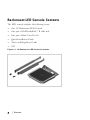
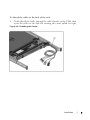
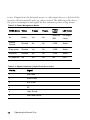
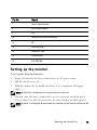
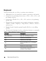
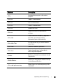
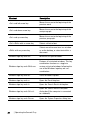
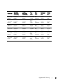
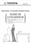
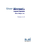
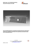
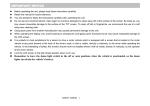
Dell 1U Rackmount LED Console
User's Guide
Notes, Cautions, and Warnings
NOTE: A NOTE indicates important information that helps you make
better use of your computer.
CAUTION: A CAUTION indicates potential damage to hardware or
loss of data if instructions are not followed.
WARNING: A WARNING indicates a potential for property damage,
personal injury, or death.
____________________
Information in this document is subject to change without notice.
© 2012 Dell Inc. All rights reserved.
Reproduction of these materials in any manner whatsoever without the written
permission of Dell Inc. is strictly forbidden.
Trademarks used in this text: Dell™, the DELL logo are trademarks of Dell Inc.
Other trademarks and trade names may be used in this document to refer to either the
entities claiming the marks and names or their products. Dell Inc. disclaims any
proprietary interest in trademarks and trade names other than its own.
590-1135-501A
Model FPM185
September 2012
Contents
Overview
Rackmount LED Console Contents
Installation
1
2
3
Installing into the Rack
3
Operating the Console Tray
10
Features
Power Management Modes
10
10
Setting up the monitor
12
Power Management System
13
Using the Front Panel
13
Using the OSD Menu
Brightness/Contrast
Auto Adjust
Input Source
Color Settings
Display Settings
Other Settings
Personalize
14
15
15
15
15
16
17
18
USB 3.0
18
Keyboard
19
Touch Pad
22
Removal from the Rack
23
Contentsxxx | xxx1
Appendix A: Safety Precautions
General
27
27
Appendix B: Timing
30
Appendix C: Technical Support
32
Contentsxxx | xxx2
1
Overview
The Dell 1U Rackmount LED Console is designed from the latest flat-panel
monitor technology and provides a performance-oriented product with no
mercury. This product uses a D-Sub 15-pin VGA connector and can support 28
VESA modes, VESA DPMS power management and plug-and-play function. Its
design conserves rack space compared to a traditional CRT monitor. In
addition, the flat-panel monitor consumes less power.
Overviewxxx | xxx1
Rackmount LED Console Contents
The LED console includes the following items: •
One 1U Rackmount LED Console
•
One pair of Dell ReadyRails™ II slide rails
•
One pair of Rack Travel Locks
•
Quick Installation Guide
•
Safety and Regulatory Guide
•
CD Figure 1.1. 1U Rackmount LED Console Contents
2xxx | Overviewxxx
2
Installation
Installing into the Rack
This section provides instructions for installing the Dell 1U Rackmount
LED Console Tray in a four-post rack cabinet. The pullout tray assembly
features a keyboard with touchpad and a flat-panel monitor that rotates up from
the console tray for use. An attached cable-management arm routes the monitor,
power, USB and keyboard/touchpad cables to the back of the rack. The monitor's
power supply is installed on the console tray.
Install the console tray using Dell ReadyRails™ II slide rails in any system
manufacturer's rack cabinets.
For removal instructions, see "Removal from the Rack" on page 23
NOTE: 1U of free rack space is required to mount the 1U Rackmount LED Console Tray.
Installationxxx | xxx3
To install tool-less rails: 1
Position the left and right rail end pieces labeled FRONT facing inward, and
orient each end piece to seat in the holes on the front side of the vertical
rack flanges.
2
Align each end piece in the bottom and top holes of the desired U spaces
until the latch clicks into place.
3
Engage the back end of the rail until it fully seats on the vertical rack flange
and the latch clicks into place.
Figure 2.1. Installing Tool-less Rails
4xxx | Installationxxx
Preparing to install tooled rails: 1
Remove the screw from the front mounting bracket using a torx-head
screwdriver, then remove the pins from the front and rear mounting brackets
using a flat-tipped screwdriver.
2
Pull and rotate the rail latch subassemblies to remove them from the
mounting brackets.
Figure 2.2. Preparing to Install Tooled Rails
Installationxxx | xxx5
Installing tooled rails: 1
Attach the left and right mounting rails to the front vertical rack flanges
using two pairs of screws.
2
Slide the left and right back brackets forward against the rear vertical rack
flanges and attach them using two pairs of screws.
Figure 2.3. Installing Tooled Rails
6xxx | Installationxxx
To install the console tray: NOTE: Ensure that the system is properly supported until the chassis rail members are
inserted into the slide rails on both sides.
1
Pull the sliding rails out of the rack until they are fully extended.
2
Align and insert the ends of the chassis rail members into the ends of the
rails.
3
Push the system inward until the chassis rail members are fully inserted.
4
Pull and push the console tray in and out of the rack until it slides smoothly
within the rack.
Figure 2.4. Installing the Console Tray
Installationxxx | xxx7
To install the cable management arm (CMA): 1
From the back of the rack, cut the zip tie that secures the CMA to the back
of the tray.
2
Swing the free end of the CMA out to the bracket on the end of the left
stationary rail.
3
Attach the CMA to the bracket with the captive screw on the end of the
arm.
Figure 2.5. Installing the Cable Management Arm
8xxx | Installationxxx
To thread the cables to the back of the rack: 1
Gently thread the cables through the cable channel on the CMA, then
secure the cables to the slide rail, ensuring they aren't pulled too tight.
Figure 2.6. Threading the Cables
Installationxxx | xxx9
3
Operating the Console Tray
NOTE: This console tray features a capacitive touch screen interface. Touch the
LED located below a desired icon. Power is its own icon.
Features
This product has the following features.
Table 3.1: Features
Feature
Description
Optimal resolution and refresh
1366 x 768 at 60 Hz
Active Matrix Thin Film Transistor (TFT)
Screen type
Liquid Crystal Display (LCD)
Display active area
409.8 mm x 230.4 mm (13.3 inches x 10.64
inches)
Physical size
358.5 mm x 17.5 mm x 296.5 mm
(width x depth x height)
(14.1 inches x 0.689 inches x 11.67 inches)
Weight (LCD panel only)
2.0 kg (4.41 lbs)
Power Management Modes
If you have a VESA DPMS compliant display card or software installed in your
system, the monitor can automatically reduce its power consumption when not
Operating the Console Trayxxx | xxx10
in use. If input from the keyboard, mouse or other input devices is detected, the
monitor will automatically wake up, unless stowed. The following table shows
the power consumption and signals for this automatic power saving feature.
Table 3.2: Power Management Modes
VESA Mode
Video
H-sync
V-sync
Power
Used
LED Color
On
Active
Yes
Yes
Maximum
20W
Full bright
<blue>
Stowed
Position
Blanked
No
Yes
<0.5W
Amber
Sleep mode
Blanked
Yes
No
<0.5W
Amber
Active-off
Blanked
No
No
<0.5W
Amber
DC power off
NA
NA
NA
0W
Dark
Table 3.3: Signal Connector (15-pin D-sub Connector)
Pin No.
Signal
1
Red Video
2
Green Video
3
Blue Video
4
NC
5
Logic Ground
6
Red Video Ground
11xxx | Operating the Console Trayxxx
Pin No.
Signal
7
Green Video Ground
8
Blue Video Ground
9
VCC
10
Identify VGA Cable Connection
11
NC
12
SDA (DDC1/2B)
13
Horizontal Sync
14
Vertical Sync
15
SCL (DDC2B)
Setting up the monitor
To set up the flat-panel monitor: 1
Ensure the monitor has been connected to an AC power source.
2
Pull the monitor tray out.
3
Hold the monitor by its handle and rotate it to a maximum 110-degree
angle.
NOTE: Use the tray's handle to push and pull the tray in the rack.
4
The first time the unit is connected to power, you must touch the power
icon to turn it on. After the first time, the unit will turn on when opened.
NOTE: If power is completely disconnected, the console tray will default into Active-Off
mode.
Operating the Console Trayxxx | xxx12
Power Management System
The flat-panel monitor complies with the VESA DPMS (version 11) power
management standard. The VESA DPMS proposal provides four phases of power
saving modes by detecting horizontal or vertical sync signals.
The LED indicator color will be amber when the monitor is in power-saving
mode.
Using the Front Panel
Use the icons on the front of the monitor to adjust the image settings.
Table 3.4: Front Panel Controls Descriptons
Icon
Mode
Description
Preset Modes
Select
Touch this icon to select image modes on your monitor.
Brightness/Contrast
Touch this icon for direct access to the brightness and
contrast menu.
Auto Adjust
Touch this icon to automatically adjust the monitor.
OSD Menu
Touch this icon to open the On-Screen Display (OSD).
Exit
Touch this icon to exit the OSD Menu.
13xxx | Operating the Console Trayxxx
Icon
Mode
Description
Personalize
Touch this icon to customize the monitor with your
personal settings.
Power
Touch this icon to turn the monitor's power off and on.
When the LED is blue, the monitor is on and fully
functional. When the LED is amber, the monitor is in
power-save mode.
Using the OSD Menu
The flat-panel monitor features an On-Screen Display (OSD). To access the
OSD's main menu, press the OSD Menu icon on the front panel of the monitor.
Use the function icons to scroll through the menu and make changes to the
selected menu items.
Table 3.5: Function Icon Descriptions
Icon
Function
Description
Up arrow
Scroll up in the menu
Down
arrow
Scroll down in the menu
Checkmark Accept change
Exit
Exit the OSD menu.
Operating the Console Trayxxx | xxx14
Icon
Function
Description
Return
Return to the previous menu.
Right
arrow
Once you've selected an item from the menu, click the right
arrow to access its parameters.
Toggle
Switch between selections.
Sliders
When adjusting color settings, you can use the sliders.
NOTE: If you change the settings and then proceed to another menu or exit the
OSD menu, the monitor automatically saves the changes.
Brightness/Contrast
Click the up arrow to increase the brightness or contrast and click the down
arrow to decrease the brightness or contrast. The range is from 0-100 for both
the brightness and contrast.
Auto Adjust
Click the checkmark to automatically adjust the screen to optimize the display
settings. In most cases, the Auto Adjust produces the best image for your
configuration.
Input Source
Click the checkmark to scan for available input signals.
NOTE: VGA is the only input signal supported.
Color Settings
You can set the image mode and color format under the Color Settings menu.
15xxx | Operating the Console Trayxxx
Preset Modes
From this menu, you can select Standard, Warm, Cool and Custom color
modes. If you select the Custom color mode, it brings up RGB scales from 1100.
Reset Color Settings
Returns the color settings to the factory default.
Display Settings
You can adjust the image under the Display Settings menu.
Wide Mode
Set the image ratio as 1:1, Aspect or Full Screen.
NOTE: Wide Mode adjustment is not required at the optimal preset resolution of 1366 x
768.
Horizontal Position
Click the up and down arrows to adjust the image left and right.
Vertical Position
Click the up and down arrows to adjust the image up and down.
Sharpness
Click the up and down arrows to adjust the sharpness, making the image look
softer or sharper.
Pixel Clock and Phase
The Pixel Clock and Phase settings allow you to adjust the monitor. Click the
up and down arrows to adjust the image quality. Use Pixel Clock to set coarse
settings, and Phase to set fine settings.
Display Info
Displays the monitor's current settings.
Operating the Console Trayxxx | xxx16
Reset Display Settings
Select this option to restore settings to the factory default.
Other Settings
From the Other Settings menu, you can adjust the OSD settings.
Language
Select which language the OSD uses.
Menu Transparency
From this menu, you can adjust the OSD background from opaque to
transparent.
Menu Timer
Use the up and down arrows to select the number of seconds, in five-second
increments, the OSD will remain active after the last time you touch a button.
Menu Lock
From this menu, you can control user access to adjustments. When set to Lock,
no user adjustments are allowed. To unlock, hold the X (Exit) button on the
front panel of the monitor for 15 seconds.
NOTE: Menu Lock can also be activated by holding the X (Exit) button on the front
panel of the monitor for 15 seconds.
DDC/CI
DDC/CI (Display Data Channel/Command Interface) allows your monitor
parameters (brightness, color balance, etc.) to be adjustable via software on your
computer. Enable this feature for best user experience and optimum
performance of your monitor.
LCD Conditioning
If an image appears to be stuck on the monitor, enable LCD Conditioning to
help eliminate any image retention. Using the LCD Conditioning feature may
17xxx | Operating the Console Trayxxx
take several hours. You can safely stop the LCD Conditioning by turning the
monitor off.
NOTE: The LCD Conditioning feature does not remove burn-in.
Factory Reset
Resets all OSD settings to the factory default.
Personalize
There are three shortcut keys on the front panel of the monitor. From the
Personalize menu, you can assign a control menu to a shortcut key for quick
access.
USB 3.0
This device has two USB 3.0 compliant pass-through ports, which provide faster
data transmission between your console and connected USB devices. However, if
you are using USB 1.1 or 2.0 targets, the maximum speed will be limited to
those devices' thresholds. See the following table.
Table 3.6: USB Maximum Speed Chart
Device/Target USB 1.1 Target
USB 2.0 Target
USB 3.0 Target
USB 1.1
Device
12 megabits per
second
12 megabits per
second
12 megabits per
second
USB 2.0
Device
12 megabits per
second
480 megabits per
second
480 megabits per
second
USB 3.0
Device
12 megabits per
second
480 megabits per
second
4.8 gigabits per
second
NOTE: The device is limited to 900 mA with a USB 3.0 target and 500 mA with a USB 2.0
target.
Operating the Console Trayxxx | xxx18
Keyboard
Your keyboard provides sets of keys to perform various functions:
•
Alphanumeric keys for typing letters, numbers, punctuation, and symbols.
•
Control keys for performing certain actions: <Ctrl>, <Alt>, <Esc>, and
the Windows logo key.
•
Function keys, labeled <F1>,< F2>, <F3>, and so on, for performing
specific tasks.
•
Navigation keys for moving the cursor around in documents or windows:
<Home>, <End>, <Page Up>, <Page Down>, <Delete>, <Insert >
and arrow keys
•
Numeric keypad of numbers grouped together like those on an adding
machine.
•
The keyboard is limited to four key combination shortcuts or commands.
Table 3.7: General Windows® Keyboard Shortcuts
Shortcut
Description
<Ctrl><Shift><Esc>
Opens the Task Manager window.
<F2>
Renames the selected item.
<F3>
Searches for a file or folder.
<F4>
Displays the Address bar list in Windows
Explorer.
<F5>
Refreshes the active window.
<F6>
Cycles through screen elements in a
window or on the desktop.
19xxx | Operating the Console Trayxxx
Shortcut
Description
<F10>
Activates the menu bar in the active
program.
<Ctrl><c>
Copies a selected item.
<Ctrl><x>
Cuts a selected item.
<Ctrl><v>
Pastes a selected item.
<Ctrl><z>
Undoes an action.
<Ctrl><a>
Selects all items in a document or
window.
<Ctrl><F4>
Closes the active window (in programs
that allow you to have multiple
documents open simultaneously).
<Ctrl><Alt><Tab>
Uses the arrow keys to switch between
open items.
<Alt><Tab>
Switches between open items.
<Alt><Esc>
Cycles through items in the order in
which they were opened.
<Delete>
Deletes a selected item and move it to the
Recycle Bin.
<Shift><Delete>
Deletes the selected item without moving
it to the Recycle Bin first.
<Ctrl> and right-arrow key
Moves the cursor to the beginning of the
next word.
Operating the Console Trayxxx | xxx20
Shortcut
Description
<Ctrl> and left-arrow key
Moves the cursor to the beginning of the
previous word.
<Ctrl> and down-arrow key
Moves the cursor to the beginning of the
next paragraph.
<Ctrl> and up-arrow key
Moves the cursor to the beginning of the
previous paragraph.
<Ctrl><Shift> with an arrow key
Selects a block of text.
<Shift> with any arrow key
Selects more than one item in a window
or on the desktop, or select text within a
document.
Windows logo key and <m>
Minimizes all open windows.
Windows logo key and <Shift><m>
Restores all minimized windows. This key
combination functions as a toggle to
restore minimized windows following the
use of the Windows logo key and <m>
combination.
Windows logo key and <e>
Starts Windows Explorer.
Windows logo key and <r>
Opens the Run dialog box.
Windows logo key and <f>
Opens the Search Results dialog box.
Windows logo key and <Ctrl><f>
Opens the Search Results-Computer
dialog box (if the computer is connected
to a network).
Windows logo key and <Pause>
Opens the System Properties dialog box.
21xxx | Operating the Console Trayxxx
Touch Pad
You can use your finger for touch input to move the cursor or select objects on
the screen:
•
To move the cursor, lightly slide your finger over the touch pad.
•
To select an object, lightly tap once on the surface of the touch pad or use
your thumb to press the left touch-pad button.
•
To select and move (or drag) an object, position the cursor on the object
and tap twice on the touch pad. On the second tap, leave your finger on the
touch pad and move the selected object by sliding your finger over the
surface.
•
To double-click an object, position the cursor on the object and tap twice
on the touch pad or use your thumb to press the left touch pad button
twice.
To clean the touch pad: 1
Using a dry, lint-free cloth, wipe gently across the surface of the touch pad.
Operating the Console Trayxxx | xxx22
4
Removal from the Rack
This section provides instructions for removing the Dell 1U Rackmount
LED console tray from a four-post rack cabinet.
Removal from the Rackxxx | xxx23
To remove the console tray from the rack: 1
From the back of the rack, unscrew the captive screw from the Cable
Management Arm (CMA) to remove it from the rail.
2
Pull the console tray out until the slide rails are in a fully extended position.
3
Press the blue tabs on each side of the console tray.
4
While pressing the tabs in Step 2, slide the console tray out of the rack.
Figure 4.1. Removing the Console Tray From the Rack
24xxx | Removal from the Rackxxx
To remove tool-less rails: 1
At the front of the rack, pull the blue tab to release the lock.
2
Repeat at the back of the rack and slide the rail out of the rack.
Figure 4.2. Removing Tool-less Rails
Removal from the Rackxxx | xxx25
To remove tooled rails: 1
Unscrew the two pairs of screws to detach the left and right brackets from
the front vertical rack flanges.
2
Unscrew the two pairs of screws to detach the left and right mounting rails
from the rear vertical rack flanges.
Figure 4.3. Removing Tooled Rails
26xxx | Removal from the Rackxxx
Appendix A: Safety Precautions
Use the following safety guidelines to help ensure your own personal safety and
to help protect your system and working environment from potential damage.
CAUTION: The power supplies in your system may produce high voltages and energy
hazards, which can cause bodily harm. Only trained service technicians are
authorized to remove the covers and access any of the components inside the system.
This document pertains only to the Dell 1U Rackmount LED Console Tray.
You should also read and follow the additional safety instructions.
•
Dell Remote 1U Rackmount LED Console Tray Quick Installation Guide
•
Dell Safety, Environmental and Regulatory Guide.
General
•
Observe and follow service markings.
•
Do not service any product except as explained in your system
documentation.
•
Opening or removing covers that are marked with the triangular symbol with
a lightning bolt may expose you to electrical shock.
•
Components inside these compartments should be serviced only by a
trained service technician.
•
Do not attempt to open this product unless you have proper service
personnel documentation.
If any of the following conditions occur, unplug the product from the electrical
outlet and replace the part or contact your trained service provider:
- The power cable, extension cable, or plug is damaged.
Appendix A: Safety Precautionsxxx | xxx27
- An object has fallen into the product.
- The product has been exposed to water.
- The product has been dropped or damaged.
- The product does not operate correctly when you follow the
operating instructions.
•
Keep your system away from radiators and heat sources. Also, do not block
cooling vents.
•
Do not spill food or liquids on your system components, and never operate
the product in a wet environment. If the system gets wet, see the
appropriate section in your troubleshooting guide or contact your trained
service provider.
•
Use the product only with approved equipment.
•
Allow the product to cool before removing covers or touching internal
components.
•
Operate the product only from the type of external power source indicated
on the electrical ratings label. If you are not sure of the type of power source
required, consult your service provider or local power company.
NOTE: To help avoid damaging your system, be sure the voltage selection switch (if
provided) on the power supply is set for the voltage that most closely matches the AC
power available in your location. Also be sure that your monitor and attached devices
are electrically rated to operate.
•
Be sure that your monitor and attached devices are electrically rated to
operate with the power available in your location.
•
The console tray has custom connectors for the power supply. Be sure you
use only the power supply supplied with the console tray.
•
Use only power cables provided with this product.
•
To help prevent electric shock, plug the system and peripheral power cables
into properly grounded electrical outlets. These cables are equipped with
three-prong plugs to help ensure proper grounding. Do not use adaptor plugs
or remove the grounding prong from a cable.
Appendix A: Safety Precautionsxxx | xxx28
•
Observe extension cable and power strip ratings. Make sure that the total
ampere rating of all products plugged into the power strip does not exceed
80 percent of the ampere ratings limit for the power strip.
•
To help protect your system from sudden, transient increases and decreases
in electrical power, use a surge suppressor, line conditioner, or
uninterruptible power supply (UPS).
•
Position system cables and power cables carefully. Route cables so that they
cannot be stepped on or tripped over. Be sure that nothing rests on any
cables.
•
Do not modify power cables or plugs. Consult a licensed electrician or your
power company for site modifications. Always follow your local/national
wiring rules.
Appendix A: Safety Precautionsxxx | xxx29
Appendix B: Timing
Table 4.1: Supported Timing
Resolution
Horizontal
Frequency
and Polarity
Vertical
Frequency
and Polarity
Pixel
Clock
Scan
Type
Horizontal
Sync
Vertical
Sync
640 x 480
@ 60 Hz
31.469 kHz
Negative
59.940 Hz
Negative
25.175
MHz
39.72 ns
Noninterlaced
3.813 us
96 dots
.064 ms
2 lines
640 x 480
@ 75 Hz
37.5 kHz
Negative
75 Hz
Negative
31.5 MHz
31.75 ns
Noninterlaced
2.032 us
64 dots
.08 ms
3 lines
800 x 600
@ 60 Hz
37.879 kHz
Positive
60.317 Hz
Positive
40 MHz
25 ns
Noninterlaced
3.2 us
128 dots
.106 ms
4 lines
800 x 600
@ 75 Hz
46.875 kHz
Positive
75 Hz
Positive
49.5 MHz
20.2 ns
Noninterlaced
1.616 us
80 dots
.064 ms
3 lines
1024 x 768
@ 60 Hz
43.363 kHz
Negative
60.004 Hz
Negative
65 MHz
15.38 ns
Noninterlaced
2.092 us
136 dots
.124 ms
6 lines
1024 x 768
@ 75 Hz
60.023 kHz
Positive
75.029 Hz
Positive
78.75
MHz
12.7 ns
Noninterlaced
1.219 us
96 dots
.05 ms
3 lines
1152 x 864
@ 60 Hz
54.348 kHz
Positive
60.053 Hz
Positive
80 MHz
12.5 ns
Noninterlaced
1.2 us
96 dots
.055 ms
3 lines
1152 x 864
@ 75 Hz
67.5 kHz
Positive
75 Hz
Positive
108 MHz
9.26 ns
Noninterlaced
1.185 us
128 dots
.044 ms
3 lines
1366 x 768
@ 60 Hz
47.712 kHz
Positive
60.015 Hz
Positive
85.5 MHz
11.7 ns
Noninterlaced
1.31 us
112 dots
.126 ms
6 lines
1366 x 768
@ 75 Hz
60.15 kHz
Positive
75 Hz
Positive
110.195
MHz
9.07 ns
Noninterlaced
1.307 us
144 dots
.049 ms
3 lines
Appendix B: Timingxxx | xxx30
Resolution
Horizontal
Frequency
and Polarity
Vertical
Frequency
and Polarity
Pixel
Clock
Scan
Type
Horizontal
Sync
Vertical
Sync
1280 x 800
@ 60 Hz
49.702 kHz
Negative
59.81 Hz
Positive
83.5 MHz
11.98 ns
Noninterlaced
1.533 us
128 dots
.121 ms
6 lines
1280 x 800
@ 75 Hz
62.795 kHz
Negative
74.934 Hz
Positive
106.5
MHz
9.39 ns
Noninterlaced
1.202 us
128 dots
.096 ms
6 lines
1280 x 1024
@ 60 Hz
63.981 kHz
Positive
60.02 Hz
Positive
108 MHz
9.26 ns
Noninterlaced
1.037 us
112 dots
.047 ms
3 lines
1280 x 1024
@ 75 Hz
79.976 kHz
Positive
75.025 Hz
Positive
135 MHz
7.41 ns
Noninterlaced
1.067 us
144 dots
.038 ms
3 lines
1140 x 900
@ 60 Hz
55.935 kHz
Negative
59.877 Hz
Positive
106.5
MHz
9.39 ns
Noninterlaced
1.427 us
152 dots
.107 ms
6 lines
1140 x 900
@75 Hz
70.635 kHz
Negative
74.984 Hz
Positive
136.75
MHz
7.31 ns
Noninterlaced
1.112 us
152 dots
.085 ms
6 lines
Appendix B: Timingxxx | xxx31
Appendix C: Technical Support
Our Technical Support staff is ready to assist you with any installation or
operating issues you encounter with your Dell product. If an issue should
develop, follow the steps below for the fastest possible service.
To resolve an issue:
1
Check the pertinent section of this manual to see if the issue can be
resolved by following the procedures outlined.
2
Check our web site at dell.com/support to search the knowledge base or use
the on-line service request.
3
Call the Dell Technical Support location nearest you.
Appendix C: Technical Supportxxx | xxx32