1
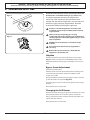
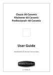
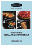
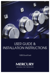
Classic 60 Gas Kitchener 60 Gas Professional+ 60 Gas User Guide Installation & Service Instructions U110331_02A Contents 1. Before You Start... 1 6.Troubleshooting 13 Installation and Maintenance 1 Peculiar smells 1 7.Installation 14 Ventilation1 Personal Safety 1 Cooker Care 2 Cleaning2 If a Fault Occurs 2. Cooker Overview 2 3 Safety Requirements and Regulations 14 Provision of Ventilation 14 Location of Cooker 15 Positioning the Cooker 15 Levelling the Cooker 15 Moving the Cooker 15 3 Gas Connection 16 The Griddle 4 Electrical Connection 16 The Grill 5 Final Checks 17 The Ovens 6 Customer Care 17 The Clock 7 Oven Accessories 8 Main Oven Light 8 Cooking Tips Tips on Cooking 5. 14 Hotplate Burners Operation6 3. Dear Installer Cleaning Your Cooker 9 9 8. Conversion to LP Gas 18 Hotplate18 Bypass Screw Adjustment 18 Changing the Grill Burner 18 Changing the Oven Burners 19 Pressure Testing 19 10 9. Circuit Diagram 20 Hotplate Burners 10 The Griddle 10 10. Technical Data 21 Grill10 Control Panel and Doors 11 Top Oven Door Panel 11 Removal of the Inner Glass 11 Ovens11 Due to our policy of continual improvement, we reserve the right to change specifications without prior notice. 1. Before You Start... Thank you for buying this cooker. It should give you many years of trouble-free cooking if installed and operated correctly. It is important that you read this section before you start, particularly if you have not used a gas cooker before. use the cooker for a long time, open a window or turn on an extractor fan. Personal Safety This appliance is designed for domestic cooking nn only. Using it for any other purpose could invalidate DO NOT modify this appliance. nn This appliance is not intended for use by persons nn (including children) with reduced physical, sensory any warranty or liability claim. In particular, the oven should NOT be used for heating the kitchen – besides invalidating claims this wastes fuel and may overheat the control knobs. or mental capabilities, or lack of experience and knowledge, unless they have been given supervision or instruction concerning use of the appliance by a person responsible for their safety. Installation and Maintenance In the UK, the cooker must be installed by a Gas Safe registered engineer. All installations must be in accordance with the relevant instructions in this booklet, with the relevant national and local regulations, and with the local gas and electricity supply companies’ requirements. Children or infirm persons should be supervised to nn ensure that they do not play with the appliance. Make sure that the gas supply is turned on and that the cooker is wired in and switched on (the cooker needs electricity). Danger of fire: DO NOT store items on the cooking nn surfaces. CAUTION: A long term cooking process has to be nn supervised from time to time. A short term cooking process has to be supervised continuously. Accessible parts will become hot during use and will nn retain heat even after you have stopped cooking. It is recommended that this appliance is serviced annually. Keep babies and children away from the cooker and never wear loose-fitting or hanging clothes while the appliance is in use. Only a qualified service engineer should service the cooker, and only approved spare parts should be used. Always allow the cooker to cool and then switch it off at the mains before cleaning or carrying out any maintenance work, unless specified otherwise in this guide. DO NOT use a steam cleaner to clean the cooker. Always be certain that the controls are in the OFF position when the oven is not in use, and before attempting to clean the cooker. nn Stabilizing brackets must be installed in order to nn prevent tipping of the appliance. When the oven is on, DO NOT leave the oven door nn open for longer than necessary, otherwise the Peculiar smells control knobs may become very hot. When you first use your cooker it may give off a slight odour. This should stop after a little use. While the oven door is open do not let children climb nn on the door or sit on it. Before using for the first time, make sure that all packing materials have been removed and then, to dispel manufacturing odours, turn the ovens to maximum temperature and run for 45 minutes. DO NOT spray aerosols in the vicinity of the cooker nn while it is on. Use dry oven gloves when applicable – using damp gloves might result in steam burns when you touch a hot surface. Do not use a towel or other bulky cloth in place of a glove – it might catch fire if brought into contact with a hot surface. Make sure the room is well ventilated to the outside (see ‘Ventilation’ below). People with respiratory or allergy problems should vacate the area for this brief period. NEVER operate the cooker with wet hands. nn DO NOT use aluminium foil to cover shelves, linings nn or the oven roof. Ventilation The use of a cooking appliance results in the production of heat and moisture in the room in which it is installed. Therefore, ensure that the kitchen is well ventilated: keep natural ventilation holes open or install a powered cooker hood that vents outside. If you have several burners on, or NEVER heat unopened food containers. Pressure nn build up may make the containers burst and cause injury. DO NOT use unstable saucepans. Always ensure that nn you position the handles away from the edge of the hotplate. Never leave the hotplate unattended at high heat settings. Pans boiling over can cause smoking, and greasy spills may 1 catch on fire. Use a deep fat thermometer whenever possible to prevent fat overheating beyond the smoking point. away any moisture with a soft cloth. This will also help to prevent soiling and discolouration of the oven exterior by cooking vapours. NEVER leave a chip pan unattended. Always heat fat nn slowly, and watch as it heats. Deep fry pans should Cleaning be only one third full of fat. Filling the pan too full of fat can cause spill over when food is added. If you use a combination of oils or fats in frying, stir them together before heating, or as the fats melt. Foods for frying should be as dry as possible. Frost on frozen foods or moisture on fresh foods can cause hot fat to bubble up and over the sides of the pan. Carefully watch for spills or overheating of foods when frying at high or medium high temperatures. Never try to move a pan of hot fat, especially a deep fat fryer. Wait until the fat is cool. DO NOT use abrasive cleaners/pads, oven aerosols/ nn pads or stain removers on the surface. In the interests of hygiene and safety, the cooker should be kept clean at all times as a build up in fats and other food stuff could result in a fire. Clean only the parts listed in this guide. Clean with caution. If a wet sponge or cloth is used to wipe spills on a hot surface, be careful to avoid steam burns. Some cleansers can produce noxious fumes if applied to a hot surface. Do not use the top of the flue (the slot along the back of the cooker) for warming plates, dishes, drying tea towels or softening butter. If a Fault Occurs DO NOT use water on grease fires and never pick up a flaming pan. Turn off the controls and then smother a flaming pan on a surface unit by covering the pan completely with a well fitting lid or baking tray. If available, use a multipurpose dry chemical or foam-type fire extinguisher. Cooking high moisture content foods can create a ‘steam burst’ when the oven door is opened. When opening ArtNo.324-0001 Steam burst the oven stand well back and allow any steam to disperse. nn If your appliance develops a fault and you are unable to solve the problem, contact one of our service centres on the below numbers: UK Service Centre Tel: 0844 847 6711. Republic of Ireland Service Centre Tel: 051 302 333 Always keep combustible materials, e.g. curtains, and flammable liquids a safe distance away from your cooker. Take care that no water seeps into the appliance. Do not attempt to lift or move the appliance by nn pulling the door handles. NEVER allow anyone to climb or stand on the hob. nn The appliance is not intended to be operated by nn means of external timer or separated remote control system. Only certain types of glass, glass-ceramic, earthenware or other glazed containers are suitable for hotplate cooking; others may break because of the sudden change in temperature. Cooker Care As steam can condense to water droplets on the cool outer trim of the oven, it may be necessary during cooking to wipe 2 2. Cooker Overview DocNo.020-0002 - Overview - 90 Ceramic - Generic Fig.2-1 A B TOP OVEN C 1 flat shelf Rack 2 Rack 1 Rack 5 Rack 4 Rack 3 Rack 2 Rack 1 D MAIN OVEN The 60 gas cooker (Fig.2-1) has the following features: A. B. C. D. 2 flat shelves Fig.2-2 4 hotplate burners A control panel A conventional top oven and grill A main conventional oven Hotplate Burners The drawing by each of the knobs indicates which burner that knob controls. Each burner has a Flame Supervision Device (FSD) that prevents the flow of gas if the flame goes out. Fig.2-3 To ignite a hotplate burner push in and turn the associated control knob counterclockwise to the high position as indicated by the large flame symbol (), (Fig.2-2). Sparks are generated as long as the control knob is held in. If, when you let go of the control knob, the burner goes out, then the FSD has not been bypassed. Turn the control knob to the off (0) position and wait for one minute before you try again, this time making sure to hold in the control knob for slightly longer. Adjust the flame height to suit by turning the knob counterclockwise (Fig.2-3). 3 DO NOT operate the burners between the max () nn and off (0) positions. Fig.2-4 If a burner flame goes out, turn off the control knob and leave it for one minute before relighting it. Make sure that the flames are under the pans. Using a lid will help the contents boil more quickly (Fig.2-4). Large pans should be spaced well apart. ArtNo.311-0001 Right pans gas Pans and kettles with concave bases or down-turned base rims should not be used (Fig.2-5). Simmering aids, such as asbestos or mesh mats, are NOT recommended (Fig.2-6). They will reduce burner performance and could damage the pan supports. Fig.2-5 You should also avoid using unstable and misshapen pans that may tilt easily, and pans with a very small base diameter, e.g. milk pans, single egg poachers (Fig.2-7). ArtNo.311-0002 Pan with rim DO NOT use cooking vessels on the hotplate that overlap the edges. The Griddle Fig.2-6 The griddle is intended for use on the right of the hob, sitting on the smaller (1kW) and medium (1.7kW) burners (Fig.2-8). It is designed for cooking food on directly. DO NOT use pans of any kind on it. The griddle surface is non-stick and metal cooking utensils (e.g. spatulas) will damage the surface. Use heat resistant plastic or wooden utensils. Art No. 311-0003 Simmer aids DO NOT put it crossways – it will not fit properly and nn will be unstable (Fig.2-9). Fig.2-7 DO NOT put it on any other burner – it is not nn designed to fit on any of the other pan supports. Position the griddle over the hotplate burners resting on the pan support. Check that it is securely located. The griddle can be lightly brushed with cooking oil before use. Light the hotplate burners. Adjust the flame heights to suit. ArtNo.311-0004 Tipping wok Preheat the griddle for a maximum of 5 minutes with the larger burner at 50% and smaller burner at 100% before adding food. Leaving it longer may cause damage. Turn the control knobs towards the low position, marked with the small flame symbol, to reduce the burner flames. Fig.2-8 Always leave space around the griddle for the gases nn to escape. NEVER fit two griddles side by side. nn After cooking, allow the griddle to cool before cleaning. Fig.2-9 4 The Grill Fig.2-10 Before using the grill for the first time and to dispel manufacturing odours turn the oven to the maximum temperature setting and run it empty for 45 minutes. To clear the smell make sure the room is well ventilated to the outside, by opening windows or turning on a cookerhood. We recommend that people with respiratory problems should vacate the area for this brief period. Operation Fig.2-11 The grill has a special safety device which stops the flow of gas if the flame goes out. Grill pan handle Push in and turn the control knob clockwise to select the grill function (Fig.2-10) as indicated by the large flame on the control knob. Continue pressing the knob until you see a stable flame under the grill. Grill pan If, when you release the control knob the grill goes out, then the safety device has not held in. Turn the grill control knob to off (0) position and wait for one minute. Repeat the operation but hold the control knob in for slightly longer. Fig.2-12 Adjust the grill temperature between the large flame and small flame on the control knob. Whilst grilling, the oven door should be completely nn open. Attach the grill pan handle (Fig.2-11). Ensure the grill pan handle is centralised and secure. Remove the grill pan from the grill chamber (Fig.2-12). For best results preheat the grill for a few minutes before grilling or toasting. ArtNo.330-0003 - Grill pan w handle pulled forwards Once the grill has preheated, slide the grill pan and trivet back into the grill chamber and remove the handle. Remember to leave the grill door completely open. Ensure that the grill is turned off before closing the nn door. Accessible parts may be hot when the grill is in use. nn Young children should be kept away. Always wear oven gloves when using the grill. nn 5 The Ovens Fig.2-13 Before using the ovens for the first time and to dispel manufacturing odours turn them to the maximum temperature setting and run them empty for 45 minutes. To clear the smell make sure the room is well ventilated to the outside, by opening windows or turning on a cookerhood. We recommend that people with respiratory problems should vacate the area for this brief period. Fig.2-14 Both ovens are conventional ovens. They are fitted with a special safety device which stops the flow of gas if the flame goes out. If, when you release the control knob the burner goes out, then the safety device has not held in. Turn the oven control knob to the off (0) position and wait for one minute. Repeat the operation but hold the control knob in for slightly longer. ‘S’ (Slow) Cooking Function Fig.2-15 Both ovens feature an ‘S’ setting. This is a low temperature setting for cooking food over a long period. The oven centre is set at 100 ºC. The ‘S’ setting can also be used for keeping food warm. The approximate temperature for each position is displayed in Table 2-1. Operation The Top Oven Fig.2-16 Push in and turn the control knob counter clockwise to select the ‘MAX’ position as indicated on the knob (Fig.2-13). Continue pressing the knob until the oven ignites and you see a stable flame. Adjust the control knob to select the desired setting using the graphics located around the knob (Fig.2-14). The Main Oven Mark Top Oven Temp. (ºC) Main Oven (ºC) S 100 100 1 140 140 2 150 150 3 160 160 4 180 180 5 190 190 6 200 200 7 220 220 8 230 240 9 Push in and turn the control knob counter clockwise to select the ‘9’ position as indicated on the knob (Fig.2-15). Continue pressing the knob until the oven ignites and you see a stable flame. Adjust the control knob to select the desired setting using the graphics located around the knob (Fig.2-16). 250 Table 2-1 6 The Clock Fig.2-17 The two button clock can also be used as an alarm. Setting the Clock The LCD clock is shown in (Fig.2-17). ArtNo.308-0001 - 2-button clock To set the clock press the [+] and [-] buttons simultaneously (Fig.2-18), then either the [+] or [-] button to set the correct time. Fig.2-18 Setting the Minute Minder The clock must be set before using the minute minder. The minute minder [ ] provides the ability to set a countdown from 00.01h to 23.59h, at the end of which an alarm will sound. ArtNo.306-0001 - 3-button clock Press the [+] button once. The bell symbol [ ] will flash on the display. Select the desired countdown from 00.01h to 23.59h using the [+] button (Fig.2-19). The countdown will automatically begin and the [ ] symbol will show in the display. Fig.2-19 Once the specified time has elapsed an alarm will sound and the [ ] symbol flashes. ArtNo.306-0001 - 3-button clock To stop the alarm press any button. Changing the frequency of the alarm Fig.2-20 It is possible to change the alarm frequency. Whilst the timer is showing the time of day, press and hold the [-] button (Fig.2-20). An audible signal will sound. To select the tone press the [-] button again, until the desired tone is reached. After a few seconds the tone will be saved. ArtNo.306-0001 - 3-button clock 7 Fig.2-21 Oven Accessories Shelf guard In addition to the grill pan and handle, the ovens are supplied with three flat shelves (Fig.2-21). One in the top oven and two in the main oven. The oven shelves can be easily removed and refitted. Front Fig.2-22 Pull the shelf forward until the back of the shelf is stopped by the shelf stop bumps in the oven sides (Fig.2-22). Lift up the front of the shelf so the back of the shelf will pass under the shelf stop and then pull the shelf forward (Fig.2-23). Fig.2-23 To refit the shelf, line up the shelf with a groove in the oven rack. Lift up the front so the shelf ends clear the rack stops, and then lower the front so that the shelf is level and push it fully back (Fig.2-24). Fig.2-24 Main Oven Light Fig.2-25 The main oven features a light, which is actuated via a switch on the oven control panel (Fig.2-25). 8 3. Cooking Tips Tips on Cooking Fig.3-1 If you want to cook more than one dish, choose dishes that require approximately the same cooking time. However, dishes can be ‘slowed down’ slightly by using small containers and covering them with aluminium foil, or ‘speeded up’ slightly by cooking smaller quantities or placing them in larger containers. Very perishable foods such as pork or fish should be avoided if a long delay period is planned, especially in hot weather. Whole poultry must be thoroughly defrosted before being placed in the oven. Check that meat and poultry are fully cooked before serving. General Oven Tips When you need to preheat the oven, we recommend you do so for ten minutes. Ensure that food is placed centrally on the shelf and there is sufficient room around the baking tray/dish to allow for maximum circulation. To reduce fat splashing when you add vegetables to hot fat around a roast, dry them thoroughly or brush lightly with cooking oil. Where dishes may boil and spill over during cooking, place them on a baking tray. If you want to brown the base of a pastry dish, preheat the baking tray for 15 minutes before placing the dish in the centre of the tray. If you are cooking more than one tray of similar items, for example cakes, follow these simple steps to ensure even browning; swap the trays and rotate the food through 180º halfway through the cooking cycle. Also stagger the items on the shelves (Fig.3-1). Do not place baking trays directly onto the oven base, as it interferes with the air circulation and can lead to base burning; use the lower shelf position. 9 5. Cleaning Your Cooker Fig.5-1 DocNo.042-0003 - Cleaning - CE 90 - GENERIC Isolate the electricity supply before carrying out any major cleaning. Allow the cooker to cool. A NEVER use paint solvents, washing soda, caustic nn cleaners, biological powders, bleach, chlorine based bleach cleaners, coarse abrasives or salt. DO NOT mix different cleaning products – they may nn react together with hazardous results. B All parts of the cooker can be cleaned with hot soapy water – but take care that no surplus water seeps into the appliance. C D Remember to switch on the electricity supply before re-using the cooker. Hotplate Burners A – Cap, B – Head, C – Electrode, D – Base The burner heads and caps can be removed for cleaning. DO NOT put the burner heads in a dishwasher. nn Make sure they are absolutely dry before replacing them. Remove the pan supports, caps and heads of the burners Wipe and clean the hotplate with warm soapy water. Wash the caps and heads and rinse them. Do not leave them wet, immediately dry them with a kitchen towel. After cleaning ensure they are re-assembled correctly (Fig.5-1). The Griddle Always clean the griddle after use. Allow it to cool completely before removing. Immerse the griddle plate in hot soapy water. Use a soft cloth or, for stubborn stains, a nylon washing up brush. Note: If the griddle is washed in a dishwasher then some dishwasher residue may appear on the back. This is normal and will not affect the performance of your griddle. Grill The grill pan can be easily removed for cleaning. The grill pan and trivet should be washed in hot soapy water. After grilling meats or any foods that soil, leave to soak for a few minutes immediately after use. Stubborn particles may be removed from the trivet using a nylon brush. Alternatively, the grill pan can be washed in a dishwasher. Before you remove any of the grill parts for cleaning, nn make sure that they are cool, or use oven gloves. DO NOT use any abrasive substances. nn 10 Control Panel and Doors Fig.5-2 Avoid using any abrasive cleaners, including cream cleaners. For best results, use a liquid detergent. The same cleaner can also be used on the doors, or alternatively, using a soft cloth wrung out in clean hot soapy water. You can use the same method for cleaning the control panel and knobs. After cleaning, polish with a dry cloth. Top Oven Door Panel The top oven door can be removed for ease of cleaning. Fig.5-3 Open the oven door fully and release the saddle brackets situated either side (Fig.5-2). Ensure that the saddle brackets are opened to their end positions, to prevent the hinges from retracting into the oven door. Close the oven door until it is almost fully closed then carefully lift and un-hook the door panel from the cooker (Fig.5-3). To re-assemble, ensure that the saddle bracket and hinge mechanisms are correctly positioned (Fig.5-4). 2 Carefully replace the door panel using the hinge locating notches, then close the saddle bracket (Fig.5-5). 1 Fig.5-4 DO NOT use harsh abrasive cleaners or sharp metal nn scrapers to clean the oven door glass since they can scratch the surface, which may result in shattering of the glass. Removal of the Inner Glass The inner glass panels of the oven doors can be removed for ease of cleaning. To remove the glass panels, simply push the glass upwards and lift out of the retaining clips (Fig.5-6). Fig.5-5 notch Fig.5-6 11 Ovens Fig.5-7 Catalytic Panels The bottom oven has side catalytic panels which have been coated with a special enamel that partly cleans itself. This does not stop all marks on the lining, but helps to reduce the amount of manual cleaning needed. These panels work better above 200 °C. If you do most of your cooking below this temperature, occasionally remove the panels and wipe with a lint free cloth and hot soapy water. The panels should then be dried and replaced and the oven heated at 200 °C for about one hour. This will make sure that the panels are working effectively. Fig.5-8 Removing the Wire Shelving and Catalytic Panels to Clean The main oven lining panels can be removed for cleaning. If you wish to clean the enamel interior of the oven, you will need to remove the shelves before removing the catalytic panels Pull the wire shelves from the base clips. Then lift the shelf from the top mounts (Fig.5-7). The catalytic panels can now be removed via the six screws (Fig.5-8). Once the panels have been removed, the oven enamel interior can be cleaned. DO NOT use steel wool, oven cleaning pads, or any other materials that will scratch the surface. Refit in the reverse order. 12 6.Troubleshooting Hotplate burners will not light Fig.6-1 Make sure that the burner parts have been replaced correctly after wiping or removing for cleaning. See the ‘Cleaning’ section. ArtNo.324-0005 Oven light bulb Check that there is not a problem with your gas supply. You can do this by making sure that other gas appliances you may have are working. Do the burners spark when you push the button? Fig.6-2 If not, verify that the power is on by checking that the clock is illuminated. Steam is coming from the oven When cooking foods with high water content (e.g. oven fries) there may be some steam visible at the rear grille. Take care when opening the oven door, as there may be a momentary puff of steam when the oven door is opened. Stand well back and allow any steam to disperse. The oven is not cooking evenly If you are cooking a large item, be prepared to turn it round during cooking. If two shelves are used, check that space has been left for the heat to circulate. See the ‘Cooking Tips’ section. Check that the door seal is not damaged and that the door is held firmly against the seal. Oven not coming on Is the power on? Is the clock illuminated? If not, there may be something wrong with the power supply. Oven temperature getting hotter as the cooker gets older If turning the temperature down using the oven control knob has not worked, or has only worked for a short time, then you may need a new thermostat. This should be fitted by a service person. The oven light is not working The bulb has probably burnt out. You can buy a replacement bulb (which is not covered under the warranty) from a good electrical shop. Ask for a 25 W – 230 V lamp, FOR OVENS. It must be a special bulb, heat resistant to 300 °C (Fig.6-1). Before removing the existing bulb, turn off the power supply and make sure that the oven is cool. Open the oven door and remove the oven shelves. Unscrew the bulb cover by turning counter-clockwise. It may be very stiff (Fig.6-2). Taking care to protect your fingers with a glove in case the bulb should shatter, unscrew the old bulb. Screw in the new bulb; screw back the bulb cover. Turn on the circuit breaker and check that the bulb now lights. 13 INSTALLATION Check the appliance is electrically safe and gas sound when you have finished. 7.Installation Dear Installer In the UK the cooker must be installed in accordance with: Before you start your installation, please complete the details below, so that, if your customer has a problem relating to your installation, they will be able to contact you easily. All relevant British Standards / Codes of Practice, in particular BS 5440 Part 2. Installer’s Name For Natural Gas – BS 6172 and BS 6891. Installer’s Company For LP Gas – BS 5482-1 (when the installation is in a permanent dwelling), BS 5482-2 (when the installation is in a caravan or other non- permanent dwelling), or BS 5482-3 (when the installation is in a boat). The Gas Safety (Installation and Use) regulations. The relevant Building / IEE regulations. ArtNo.050-0011 - Installer information table Installer’s Telephone Number In the Republic of Ireland the cooker must be installed in accordance with: The installation must be carried out by a competent person and installed in accordance with the current edition of IS 813 “Domestic Gas Installations”, the current Building Regulations and reference should be made to the current ETCI rules for electrical installation. Appliance Serial Number Provision of Ventilation This appliance is not connected to a combustion products evacuation device. Particular attention shall be given to the relevant requirements regarding ventilation. Safety Requirements and Regulations This cooker must be installed in accordance with nn the relevant instructions in this booklet, with the All rooms require a window that can be opened, or equivalent, while some rooms require a permanent vent in addition to the window. relevant national and local regulations, and with the local gas and electricity supply companies’ requirements. In the UK The room containing the cooker should have an air supply in accordance with BS 5440 Part 2. All rooms require an openable window or equivalent, while some rooms require a permanent vent in addition to the openable window. The cooker should not be installed in a bedsit room with volume less than 20 m³. If it is installed in a room of volume less than 5 m³ an air vent of effective area 100 cm² is required; if it is installed in a room of volume between 5 m³ and 10 m³, an air vent of effective area 50 cm² is required; while if the volume exceeds 11 m³, no air vent is required. This cooker is a Class 2 Subclass 1 appliance. nn Before installation, make sure that the cooker is nn suitable for your gas type and supply voltage. See the data badge. The appliance must be installed in accordance with nn the regulations in force and only in a well-ventilated space. Read the instructions before installing or using this nn appliance. If there are other fuel burning appliances in the same room, BS 5440 Part 2 should be consulted to determine the requisite air vent requirements. In your own interest and that of safety, it is law that all gas appliances be installed by competent persons. Failure to install the appliance correctly could invalidate any warranty or liability claims and lead to prosecution. nn In the Republic of Ireland Reference should be made to the current edition of IS 813, which makes clear the conditions that must be met to demonstrate that sufficient ventilation is available. 14 INSTALLATION Check the appliance is electrically safe and gas sound when you have finished. Location of Cooker 650 min. with hood 700 min. without hood Fig.7-1 The cooker may be installed in a kitchen/kitchen diner but NOT in a room containing a bath or shower. 5 Note: An appliance for use on LPG must not be installed in a room or internal space below ground level, e.g. in a basement. 5 420 min. ArtNo.090-0028 - 90 cooker min spacing GENERIC This appliance is designed for domestic cooking only. Use for any other purpose could invalidate any warranty or liability claim. Positioning the Cooker Fig.7-1 shows the minimum recommended distance from the cooker to nearby surfaces. The cooker should not be placed near the fridge or on a base. All dimensions are in mm The hotplate surround should be level with, or above, any adjacent work surface. Fig.7-2 The cooker is designed to fit between kitchen cabinets spaced over 600 mm apart. 5 mm clearance either side of the appliance is recommended to allow removal of the cooker for servicing. 20 mm A minimum space of 700 mm is required between the top of the hob and a horizontal combustible surface. This can be reduced to 650 mm if a cookerhood is installed. *Any cookerhood should be installed in accordance with the hood manufacturer’s instructions. **Any splashback must be fitted in accordance with the manufacturers instructions. It is recommended that there is at least 20 mm space between the back cover of the cooker and the wall, for air circulation (Fig.7-2). Adjacent kitchen furniture must be heat resistant to 90 °C. Levelling the Cooker The cooker stands on four levelling legs. These can be adjusted 0 mm to 30 mm by turning the legs clockwise. It is recommended that you use a spirit level on a shelf in one of the ovens to check for level. Moving the Cooker On no account try and move the cooker while it is nn plugged into the electricity supply. The cooker is very heavy, so take great care. nn Do not try to lift or move the cooker by pulling on nn the door handles. We recommend that two people manoeuvre the cooker. Make sure that the floor covering is firmly fixed, or removed, to prevent it being disturbed when moving the cooker around. 15 INSTALLATION Check the appliance is electrically safe and gas sound when you have finished. Gas Connection 400 Fig.7-3 Gas inlet block This must be in accordance with the relevant standards. A 300 The flexible hose (not supplied with the cooker) must be in accordance with the relevant standards. Hoses may be purchased at most builders’ merchants. The gas supply needs to terminate with a down-facing bayonet. The connector is located just below the hotplate level at the rear of the cooker. If in doubt contact your supplier. 800 600 Because the height of the cooker can be adjusted and each connection is different, it is difficult to give precise dimensions. The maximum length of the hose should not exceed 1500mm The hose should be fitted so that both inlet and outlet connections are vertical so that the hose hangs downwards in a ‘U’ shape. All dimensions in millimetres Fig.7-4 Live: brown Earth: yellow & green L N Ideally the hose supply connection should be within the shaded area ‘A’ (Fig.7-3). Neutral: blue For Natural Gas, the flexible hose must be in accordance with BS 669. For LP Gas, it should be capable of 50 mbar pressure and 90 °C temperature rise. If in doubt contact, your supplier. After completing the gas connection, make sure that the cooker is gas sound with soapy water or leakage fluids. Electrical Connection Fig.7-5 All external wiring must comply with the IEE Regulations for the Electrical Equipment of Buildings. Connection to the electrical supply is via a plug and socket. Earth: to the terminal marked E, coloured Green/Yellow Do not use an extension lead. WARNING: THIS APPLIANCE MUST BE EARTHED. nn Three pin plugs to BS 1363 with a capacity of not less than 13 A must be used and fitted with a 13 amp fuse ‘ASTA’ approved to BS 1362. Neutral: to the terminal marked N, coloured Blue Live: to the terminal marked L, coloured Brown You MUST refit the cover after replacing the fuse. If the cover is lost, the plug MUST NOT be used until a replacement cover has been obtained from your supplier. The colour of the correct fuse carrier is that of the coloured insert in the base of the fuse recess, or stated elsewhere on the plug. Always state this colour when ordering a replacement fuse carrier. IMPORTANT: The wires in the mains lead are coloured in accordance with the following code (Fig.7-4 and Fig.7-5): Green and yellow: EARTH Blue:NEUTRAL Brown:LIVE 16 INSTALLATION Check the appliance is electrically safe and gas sound when you have finished. Final Checks Hotplate Check Check each burner in turn (refer to the ‘Hotplate Burners’ section at the front of the instructions). Grill Check Turn on the grill and check that the grill heats up. Oven Check Turn on the ovens. Check that the burners light and the ovens heat up. Customer Care Installer: Please complete your details in this guide, inform the user how to operate the cooker and hand over the instructions. Thank you. 17 WARNING – SERVICING TO BE CARRIED OUT ONLY BY AN AUTHORISED PERSON Disconnect from electricity and gas before servicing. Check appliance is safe when you have finished. 8. Conversion to LP Gas Check the ‘Technical Data’ section at the back of the book that the hob is convertible to the gas you want to use. Fig.8-1 A suitably competent person must perform the conversion. After conversion the installation must comply with the relevant regulations and also the local electricity supply company requirements. Read the instructions before converting this appliance. A Failure to convert the appliance correctly could nn invalidate any warranty or liability claims and lead A – Jet to prosecution. When servicing or replacing gas-carrying nn components disconnect from the gas supply before Fig.8-2 starting operation. Check the appliance is gas sound after completion. DO NOT use reconditioned or unauthorised gas nn controls. Disconnect from the electricity supply before nn servicing. Before electrical reconnection, check that the nn appliance is electrically safe. Hotplate Remove the burner caps and heads. Remove the old jets (Fig.8-1). Fit the new jets (see ‘Technical Data’ section at the back of the book for correct jets). Reassemble in the reverse order. Bypass Screw Adjustment Pull of the control knobs. Remove the three screws located beneath the control panel and remove the plate. Then remove the additional two screws, now visible. Gently pull off the control panel. The bypass screw is located on the side of the valve spindle (Fig.8-2). Turn the bypass screw on each control clockwise to the stop position. Reassemble in the reverse order. Changing the Grill Burner Remove the screw securing the grill burner to the oven cavity. Gently Pull the burner to reveal the injector at the back. Using a 7mm box spanner carefully remove the injector and replace with the new one. Reassemble in the reverse order. 18 WARNING – SERVICING TO BE CARRIED OUT ONLY BY AN AUTHORISED PERSON Disconnect from electricity and gas before servicing. Check appliance is safe when you have finished. Changing the Oven Burners Fig.8-3 Remove the burner shield via two screws situated on the front (Fig.8-3). Loosen the three screws which secure the burner cradle to the oven cavity. Care must be taken when moving the burner nn cradle. Gently ease the burner cradle to the right to gain access to the spring clip located on the left hand side. Depress the clip and gently lift off the burner. Remove and replace the injector using a 7mm box spanner. Be careful not to drop the injector. Reassemble in the reverse order. Pressure Testing Connect the appliance to the gas supply. Check the appliance is gas sound. The gas pressure can be measured at one of the hotplate injectors. Lift off a burner head. Fit the pressure gauge to the jet. Turn on and light one of the other burners with a match. Turn on and press in the control knob for the burner with the pressure gauge fitted. The pressure should be 29 mbar for Butane and 37 mbar for Propane. After checking the pressure, turn off the taps and replace the burner head. Reassemble burner top, making sure it is reassembled in the correct way on the burner body. Check the appliance is gas sound. nn Check operation of all the burners. nn 19 9. Circuit Diagram DocNo.090-0002 - Circuit diagrams - 90 ceramic GENERIC N L br Igniter b MO oven lamp b bk MO oven lamp switch 8/L b br 7/N br Igniter switch harness Digital timer br L1 N PE Terminal box Code Colour 20 b Blue br Brown bk Black 10. Technical Data ArtNo.100-0002 - Technical data - 90 ceramic - GENERIC This cooker is designed for use on either: Natural gas (Cat I2H) at 20 mbar or LP gas (Cat I3+) Butane 29 mbar / Propane 37 mbar INSTALLER: Please leave these instructions with the user. DATA BADGE LOCATION: Cooker back, serial number repeater badge below oven door opening. COUNTRY OF DESTINATION: GB, IE. Connections See the appliance badge for test pressures. Natural gas Butane Propane Gas (Rp ½ at rear right-hand side) 20 mbar 29 mbar 37 mbar Electric 230 / 400 V 50 Hz Dimensions Overall height Overall width Overall depth Minimum space above hotplate Refer to 'Positioning the Cooker'. minimum 895 mm maximum 925 mm 600 mm 600 mm (to fascia inc. splashback); 610 mm (over hotplate) 700 mm / 650 mm with cooker hood Ratings Hotplate Wok burner Medium burner Small burner Main oven Top oven Grill Natural Gas 20 mb Injector 3.8 kW 115 1.75 kW 97 1.0 kW 72 2.4 kW 115 2.4 kW 115 2.2 kW 110 L.P. Gas 3.8 kW (218 g/h) 1.75 kW (127 g/h) 1.0 kW (72 g/h) 2.4 kW (174 g/h) 2.4 kW (174 g/h) 2.1 kW (152 g/h) Injector 86 65 50 75 75 69 Consumption is based on G30. Trademark ArtNo.000-0018 Rangemaster name logo Models Hob Type Number of Cooking Zones Heating Technology - 1 Size - 1 Energy Efficiency - 1 Heating Technology - 2 Size - 2 Energy Efficiency - 2 Heating Technology - 3 Size - 3 Energy Efficiency - 3 Heating Technology - 4 Size - 4 Energy Efficiency - 4 Energy Efficiency of Hob This hob complies with EN 30-2-1 % % % % % Classic 60 Gas Kitchener 60 Gas Professional+ 60 Gas Gas 4 Gas Auxiliary NA Gas Semi-rapid 59 Gas Semi-rapid 59 Gas Wok 56 58 Energy saving tips • Use cookware with a flat base. • Use the correct size cookware. • Use cookware with a lid. • Minimise the amount of liquid or fat. • When liquid starts boiling, reduce the setting. 21 Oven Efficiency Trademark Classic 60 Gas Kitchener 60 Gas Professional+ 60 Gas Models Type of Oven Gas Mass kg Number of cavities 2 Heat source Gas Upper cavity Volume Energy consumption (gas) - conventional Energy consumption (gas) - forced air convection Litres 17 MJ / cycle 4.93 kWh / cycle 1.37 MJ / cycle - kWh / cycle - Energy Efficiency Index - conventional 115.3 Energy Efficiency Index - forced air convection - Energy Class B Heat source Gas Volume Lower cavity 59 Energy consumption (gas) - conventional Energy consumption (gas) - forced air convection Energy Efficiency Index - conventional Litres 41 MJ / cycle 6.12 kWh / cycle 1.70 MJ / cycle - kWh / cycle 114.7 Energy Efficiency Index - forced air convection - Energy Class B This oven complies with EN 15181 Energy saving tips Cook meals together, if possible. Keep the pre-heating time short. Do not lengthen cooking time. Do not forget to turn the appliance off at the end of cooking. Do not open the oven door during the cooking period. Consumption is based on G30. 22 DocNo.000-0001 - Back cover Rangemaster Clarence Street, Royal Leamington Spa, Warwickshire, CV31 2AD, England. Tel: +44 (0) 1926 457400 Fax: +44 (0) 1926 450526 E-mail: [email protected] w w w.rangemaster.co.uk