1
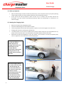
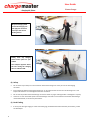
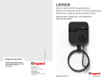
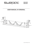
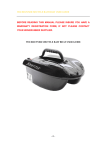
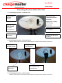
User Guide Homecharge Homecharge Products with wall bracket 1) Homecharge Functions – Tethered J1772 Docking socket for the J1772 connector Multi-function LEDs: (visible when powered) Top: Amber Middle: Green – flashing when charging Cable tidy – wrap cable around the base of the Homecharge unit. Bottom: Red On/Off key switch – quarter turn operation Mains connection flexi-conduit Charging cable with J1772 connector 2) Homecharge Functions – Tethered Type 2 Note that the key switch and multi-function LED indicators are identical to the tethered J1772 version. Docking socket for the Type2 connector Mains connection flexi-conduit Charging cable with Type 2 connector Cable tidy – wrap cable around the base of the Homecharge unit. 3) Homecharge Functions – Type 2 Socket Note that the key switch and multi-function LED indicators are identical to the tethered J1772 version. 1 User Guide Homecharge The Type 2 socket is located under the spring loaded flap. Lift flap to access the socket and plug the lead from the electric vehicle into the socket. 4) Charger Installation 2 The charger should be installed as outlined in the installation guide, which is provided for your installer and covers how the unit is to be connected. The recommended installation height for the Homecharge unit is 1200mm from the floor. The incoming mains connection is via the supplied mains wiring already installed in the flexi-conduit mounted on the lower surface of the Homecharge unit as shown above. Ensure your installer has explained how the unit has been installed and connected to the circuit breaker (RCD) in the consumer unit supplying the Homecharge. Example installation of a tethered Homecharge unit in a garage. Wall mount and incoming feed. The incoming feed is to the bottom of the unit. Recommended installation height is 1200mm. The J1772 connector is shown secured into the docking socket of the tethered Homecharge unit. User Guide Homecharge 5) Start-up sequence After the Homecharge has been installed and powered-up, it will complete its start-up sequence (flashing amber and green LEDs). The exact sequence depends on the Homecharge product. At the end of the start-up sequence, which can take up to 2 minutes, the top Amber LED will be illuminated. This LED remains illuminated permanently whilst the Homecharge is connected to an electrical supply. 6) Starting the Charging Cycle Refer to the sequence of photographs below. Connect the Homecharge unit to the Electric Vehicle. Turn the key switch from the ‘Off’ vertical position a quarter of a turn to the right to turn the unit on. Charging will commence and the green LED will flash. The ‘Off’ position can be used as an added security measure when away from your home/office for any period of time. Note that even in the ‘Off’ position, the Amber LED will remain illuminated. Note that even when the On/Off key is in the ‘On’ position – the connector is not live (and perfectly safe) until it is applied to a vehicle with the correct charging signal. For optimal usage, ensure you park your Electric Vehicle (EV) with the charging socket close to the Homecharge unit. The example opposite demonstrates a Nissan LEAF parking nose first as the charging socket is located at the front. Open the charging socket on your vehicle. Grip the handle on the Homecharge and press the release button on the connector. Remove the connector from the Homecharge docking socket. Ensure the lead is fully unwound before inserting the connector into the car socket, as shown below. 3 User Guide Homecharge Place the connector into your EV’s charging socket. Depending on the specification of the vehicle, there will be a notification (sound, light or both). Finally check the ‘charging’ green icon on the charger is lit and flashing. If the Homecharge Type2 socket product is being used, then connect the lead supplied with the Electric Vehicle into the car’s charging socket, lift the flap on the front of the Homecharge unit and insert the Type2 plug end of the lead into the Type2 socket on the front of the Homecharge. Turn the key switch from the ‘Off’ vertical position a quarter of a turn to the right to turn the unit on. Check that the green LED is lit and flashing. 7) Ending the Charging Cycle Turn the key switch from the ‘On’ position to the vertical ‘Off’ position. The green LED charging icon on the Homecharge will extinguish. Grip the handle and press the release button on the connector. Remove the connector from your EV’s charging socket. 4 If the Homecharge Type2 socket product is being used, then disconnect the lead from the Homecharge Type 2 socket and the other end from the Electric Vehicle and return the cable to its storage location. User Guide Homecharge Wrap the charging cable around the charging unit and apply the connector securely to the central docking station. Finally, close any charging socket access point on your vehicle. The example opposite shows the user closing the charging door on a Nissan LEAF. 8) Safety Do not touch any of the pins in the connector of the Homecharge unit or the pins on the EV charging connector. Ensure that the cable from the Homecharge unit, or any cable used to connect to a Homecharge unit is not frayed and that there is no damaged to the outer insulation. Do not use the product if the Homecharge connector shows any signs of being broken or damaged in any way. There are no user serviceable parts in the Homecharge and under no circumstances should the Homecharge unit be dismantled, or the security seal broken. 9) Fault Finding 5 If at any time during charging or at the end of charging, the Red bottom LED illuminates permanently, a fault has developed. User Guide Homecharge 6 Note that for Homecharge-i units, the red LED is also used to indicate poor signal strength during installation, when it will flash. If however, the red LED remains on permanently, this may be related to an earth leakage problem, in which case the RCD at the consumer unit should be reset. Firstly, turn the key switch on the Homecharge unit to the vertical ‘Off’ position. At the consumer unit, set the RCD to the ‘Off’ position and leave in the ‘Off’ position for a duration of 10 seconds. Set the RCD to the ‘On’ position and wait 2 minutes whilst the Homecharge goes through its powerup sequence. Once all LEDs have stopped flashing, check that the Homecharge unit has the top Amber LED illuminated. The Homecharge unit will now be operational again. If the problem persists and the red LED is illuminated, then it may be due to a problem with the unit. Please call the customer service number provided on the unit (0845 528 0289). If at any time the top amber LED is not illuminated, then the mains supply has been interrupted. Check the RCD in the consumer unit and reset as described above. User Guide Homecharge SPECIFICATION Input Single Phase Input voltage 230V 16A Homecharge Units: Electrical Input: Input power 3.7kW Input current 16A Connection required via consumer unit RCD rated at 20A, 30mA RCBO Type A, to EN 61009 Electrical Output: Output charging power 3.7kW Output voltage 230V Output current 16A 30A Homecharge Units: Electrical Input: Input power 7kW Input current 30A Connection required via 32A/30mA RCBO or 32A MCB and 30mA RCD in the customer’s consumer unit Electrical Output: Output charging power 7kW Output voltage 230V Output current 30A General Specification Output Connector Tethered J1772 Output charging connector IEC 62196-2 Type 1 (SAE J1772) on a 4.7m cable measured from the point the cable exits the Homecharge unit to the end of the above connector. Output Connector Type 2 Output charging connector IEC 62196-2 Type 2 Tethered Type 2 Homecharge: Output charging connector IEC 62196-2 Type 2 on a 4.7m cable measured from the point the cable exits the Homecharge unit to the end of the above connector. Safety and operational ratings o o Operating Temperature range -25 C to +70 C Operating Humidity range 5% to 95% non-condensing Standard Compliance EN 60950, IEC 61851, EN 61000-6-1 2007; EN 61000-6-3 2007 IP rating IP54 Dimensions and weight Max width 354mm Max height 204mm Depth 120mm Shipping weight typically 6.0 kg gross, 5.4 kg net 7