1
Thunderstruck Motors
EV Charger Controller v2.0
v2.1 Firmware
© 2015, Dilithium Design
EVCC v2.1 Firmware
Feb 2015
Contents Overview ............................................................................................................................................................................. 3 Installation ........................................................................................................................................................................... 5 Mechanical...................................................................................................................................................................... 5 Power .............................................................................................................................................................................. 5 J1772 ............................................................................................................................................................................... 6 Cell Loop and Buzzer ..................................................................................................................................................... 7 Driveaway Protection ..................................................................................................................................................... 8 Charge Cutback .............................................................................................................................................................. 8 CANBUS ...................................................................................................................................................................... 10 Configuration .................................................................................................................................................................... 13 Serial Port ..................................................................................................................................................................... 13 LED Operation ............................................................................................................................................................. 17 Charger Support ............................................................................................................................................................ 17 Bringup Checklist and Troubleshooting Hints ............................................................................................................. 19 Command Line Interface .................................................................................................................................................. 20 Startup Banner .............................................................................................................................................................. 20 help ............................................................................................................................................................................... 20 show .............................................................................................................................................................................. 20 set .................................................................................................................................................................................. 23 trace .............................................................................................................................................................................. 25 measure ......................................................................................................................................................................... 26 Configuring the EVCC with Multiple Chargers ............................................................................................................... 28 Line Power .................................................................................................................................................................... 28 CAN Wiring and Addressing ....................................................................................................................................... 28 EVCC Configuration .................................................................................................................................................... 29 Programming a CH4100 Charger ................................................................................................................................. 29 Charging with Multiple Chargers ................................................................................................................................. 30 Integration with CAN Enabled BMS ................................................................................................................................ 31 BMS Operation ............................................................................................................................................................. 31 EVCC Operation........................................................................................................................................................... 31 Charging Lead Acid Batteries ........................................................................................................................................... 32 Bulk Charge .................................................................................................................................................................. 32 Finishing Charge........................................................................................................................................................... 33 Float Charge ................................................................................................................................................................. 33 -1-
EVCC v2.1 Firmware
Feb 2015
Limitations .................................................................................................................................................................... 33 Mac OSX Driver Installation ............................................................................................................................................ 34 Warrantee and Support...................................................................................................................................................... 39 Document History ............................................................................................................................................................. 39 -2-
EVCC v2.1 Firmware
Feb 2015
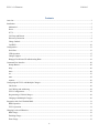
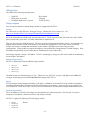
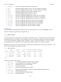
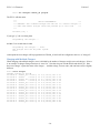
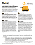
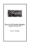
Overview The Electric Vehicle Charger Controller (EVCC) integrates charger CANBUS control and J1772 functions in a simple
to use, cost effective, and environmentally robust enclosure. Charge parameters such as maximum voltage, maximum
current, and total charge time are configured, saved in nonvolatile memory, and used when charging to control a CAN
enabled charger. The EVCC connects to analog “cell loop” Battery Management Systems (BMSs) and replaces the
head end board, acting as a BMS master. The EVCC can also interface with CAN enabled BMSs: in that case, the
EVCC provides J1772 and Charger Control functions.
Figure 1 – EVCC System Diagram
The EVCC draws negligible current (less than 0.1 mA) when off. When charging, the EVCC is started by a
momentary pushbutton and turns itself off when the charge cycle is completed. When charging, a 12V output is
provided which can light an indicator light or drive a relay.
The EVCC is configured using a simple serial interface. The serial interface is used for configuration and debugging,
but is not required for normal operation. Diagnostic commands are supported to verify proper wiring, to trace
CANBUS messages, and to retrieve charging history.
The EVCC supports the SAE J1772 standard. J1772 defines the physical connector and protocols used between the
charging station (known as the “Electric Vehicle Service Equipment”), and the Electric Vehicle. The J1772 Proximity
signal is used to determine if the charger plug is present. The J1772 Pilot signal is used to start and stop charging (by
enabling and disabling the contactor in the EVSE). “Driveaway protection” is supported so that the EV cannot be
driven if the charge cable is still plugged in.
-3-
EVCC v2.1 Firmware
Feb 2015
The EVCC supports CH4100 and ELCON CAN-enabled chargers. Charge voltage, charge current as well as overall
charge time is controlled completely by the EVCC over the CAN interface to the charger. A constant current/constant
voltage charge curve is supported for Lithium Batteries; and a three phase charge cycle is supported for Lead Acid
Batteries.
The EVCC will stop charging if the J1772 plug becomes unlocked, a cell overvoltage error occurs, there is loss of
communication between the EVCC and Charger, or the maximum configured charge time is reached. Charging also
stops at the end of a normal charge cycle. For Lithium batteries, a charge cycle ends when the charging current drops
below the minimum configured charge current.
Determining cell overvoltage errors and cell undervoltage error detection is the function of the EV Battery
Management System (BMS). The EVCC can be configured to interface with the BMS either by a cell loop or by CAN
messages (or by both). When a CAN BMS is used, the EVCC can also be configured to handle “balance cutoff”,
which lowers the charging current when a cell exceeds a “balancing threshold”.
Charging history is provided for the last sixteen charge cycles and includes: the reason that charging stopped, total
charge time, maximum voltage, maximum current, final current, and watt hours delivered.
The EVCC supports up to four parallel chargers for faster charging. When multiple chargers are configured, they are
individually CAN addressed. Work is divided evenly between the chargers and statistics are gathered and recorded on
each charger individually.
When driving, the EVCC is started by the keyswitch. When driving, the EVCC can be used as a simple “BMS
Master”: an output is provided that can be used to sound a buzzer if a cell undervoltage error is detected.
EVCC features work largely independently and it is not necessary to wire up or use all features. Installation may be
customized per customer requirements.
The EVCC is housed in a 4.55” x 5.13” x 1.67” automotive grade water-resistant enclosure. Connections are made
with a single 30pin connector. The EVCC is shipped with a pre-wired harness and with a USB to serial port cable.
-4-
EVCC v2.1 Firmware
Feb 2015
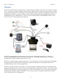
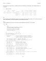
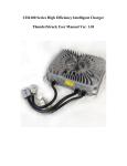
Installation Mechanical The enclosure outline is shown below. It can be mounted in any convenient location, however would ideally be located
physically close to both the charger and the J1772 charge port.
Figure 2 – EVCC Enclosure
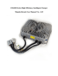
The figure below shows the 30 pin connector and wiring harness. Note the LED to the right of the connector.
Depending on model, the serial port jack may be on the front panel to the left of the connector or as part of an inline
connector.
Figure 3 – EVCC Connector and Front Panel
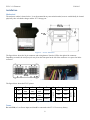
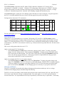
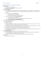
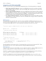
The figure below shows the EVCC pinout.
D
E
B+
Charge
Start
Cell Loop1
Buzzer
12V_Ch
J1772
Pilot
Cell Loop2
GND
GND
J1772
Proximity
Cutback
2 HotInRun
3
GND
F
G
H
CANL
CANH
CANL
CANH
12V_Sw
GND
Figure 4 – EVCC Pinout
Power B+ and GND (A3) are Power Inputs and should be connected to the EV 12V accessory battery.
-5-
J
K
reserved
C
EVSE
Disc2
Serial Port
B
EVSE
Disc1
reserved
1
A
EVCC v2.1 Firmware
Feb 2015
HotInRun is connected to the Ignition swich. Supplying +12V to HotIn will turn the EVCC on.
Charge Start is used to start charging. By grounding this input (e.g., by a momentary pushbutton switch), the EVCC
will power up and latch the power on. The EVCC automatically turns itself off when charging is complete.
12V_Ch and 12V_Sw are outputs that can be used to drive 12V indicators, relays or instrumentation. 12V_Sw is
switched to B+ when the EVCC is powered up. 12V_Ch is switched to B+ when the EVCC is Charging. These
outputs are protected by 350ma resettable fuses.
Note: The design intent of Charge Start and 12V_Ch is to mount a momentary pushbutton and a 12V
indicator near the J1772 charge port. Charging is begun by plugging in the charger plug, pushing the button,
and observing the light come on. See EVCC System Diagram, above.
The figure below shows the Power connections.
D
E
B+
Charge
Start
Cell Loop1
Buzzer
12V_Ch
J1772
Pilot
Cell Loop2
GND
GND
J1772
Proximity
Cutback
2 HotInRun
3
GND
F
G
H
CANL
CANH
CANL
CANH
12V_Sw
GND
J
K
reserved
C
EVSE
Disc2
Serial Port
B
EVSE
Disc1
reserved
1
A
Figure 5 - Power Connections
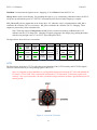
J1772 The figure below shows the J1772 EV side connector and locations of the J1772 Proximity and J1772 Pilot signals.
These are connected directly to corresponding signals at the EVCC.
Note: It is important to insure that there be a good ground connection between the J1772 Ground and both the
EV chassis / EVCC GND. This is required in order that the J1772 Pilot and J1772 Proximity signals work
correctly. One way to insure that is to make sure that the charger enclosure itself has a good connection to EV
chassis ground.
Figure 6 – Face of J1772 Socket
-6-
EVCC v2.1 Firmware
Feb 2015
The J1772 Proximity signal allows the EV and the EVSE to determine whether the J1772 charge plug is
“disconnected”, “connected” or “locked”. When the J1772 charge plug is fully inserted, it is “locked”. When the
charger release button is pressed (by thumb on the charger plug), the charge plug becomes “unlocked”, or simply
“connected”. Should the plug become “unlocked” while charging, charging will immediately stop.
The J1772 Pilot signal is used by the EV to indicate to the EVSE that it is ready for charging. Using this signal, the
the EVCC can enable and disable the relay in the EVSE that supplies line power to the charger.
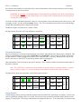
The figure below shows the J1772 connections.
D
E
B+
Charge
Start
Cell Loop1
Buzzer
12V_Ch
J1772
Pilot
Cell Loop2
GND
GND
J1772
Proximity
Cutback
2 HotInRun
3
GND
F
G
H
CANL
CANH
CANL
CANH
12V_Sw
GND
J
K
reserved
C
EVSE
Disc2
Serial Port
B
EVSE
Disc1
reserved
1
A
Figure 7 – J1772 Connections
For more information on J1772 see http://en.wikipedia.org/wiki/SAE_J1772 and https://code.google.com/p/openevse/wiki/J1772Basics).
Wiring Without J1772 Although J1772 is recommended, its use is optional. When using J1772, the EVCC J1772 Proximity signal is
connected to ground through a 150 ohm resistor built into the J1772 charge plug to indicate that the plug is “locked”.
When J1772 is not being used, the EVCC J1772 Proximity may be connected to GND through an external 150 ohm
resistor directly. (The EVCC is also tolerant of a direct [e.g., 0 ohm] connection to ground, and so the 150 ohm resistor
is optional).
Here are two wiring options that do not use J1772:
Option 1 retains most EVCC functionality.
• Wire J1772 Proximity to GND through a switch (the “charger present” switch). To charge, plug in the
charger, close the “charger present” switch, and press ChargeStart. Charging operates as designed and the
EVCC turns itself off when complete. The EVCC Drive mode operates as designed (HotInRun enables the
EVCC, the cell loop operates the buzzer). If driveaway protection is implemented, the “charger present”
switch must be turned OFF in order to operate the EV.
Option 2 is used when the EVCC is only used for charging.
• Wire J1772 Proximity directly to GND. Do not wire Charge Start. To charge, plug in the charger, and
apply 12V to HotInRun. The EVCC will power up and begin charging. When the EVCC completes charging,
it will stop sending CAN messages to the charger and turn off 12V_Ch, but will remain powered ON until
power is removed from HotInRun. To start charging again, it is necessary to cycle power to the EVCC.
Cell Loop and Buzzer The EVCC is intended to be installed with a Battery Management System that monitors per-cell over voltage
conditions when charging and per-cell undervoltage when driving.
The EVCC Cell Loop surveillance circuit measures the resistance of the circuit between Cell Loop 1 and Cell Loop 2,
if the circuit is open, then the cell loop is considered failed. The circuit applies +5v to Cell Loop1 and limits the
current to about 2ma. It is expected that the Cell Loop be provided by a solid state relay or optoisolator. (Connecting
-7-
EVCC v2.1 Firmware
Feb 2015
the cell loop to the contacts of a mechanical relay is not recommeneded, as the cell loop current may not be enough
“wetting current” for the relay contacts).
WARNING: It is strongly recommended that per-cell monitoring be performed on the pack so that charging
can be stopped if any cell exceeds a high voltage or low voltage cutoff. Lithium batteries can be dangerous if
overcharged or undercharged.
Use of the cell loop is the default operation. However, cell surveillance can be done either by the cell loop, or by CAN
messaging, or both. (See the command set bms, below). The EVCC sounds the buzzer if the a cell exceeds the high
voltage cutoff, depending on the configured bms options.
The Buzzer output is connected to B+, fused to 350ma.
The figure below shows the Cell Loop and Buzzer connections.
D
E
B+
EVSE
Disc1
EVSE
Disc2
Charge
Start
Cell Loop1
Buzzer
12V_Ch
J1772
Pilot
Cell Loop2
GND
GND
J1772
Proximity
Cutback
2 HotInRun
3
GND
F
G
H
CANL
CANH
CANL
CANH
12V_Sw
GND
J
K
reserved
C
Serial Port
B
reserved
1
A
Figure 8 – Cell Loop and Buzzer Connections
Driveaway Protection Driveaway Protection is a failsafe mechanism that prevents the EV being driven if the charger plug is connected. This
feature is implemented by the relay contacts EVSE Disc1 and EVSE Disc2. These contacts are fused to 350ma and
are open if the J1772 cable is plugged in (or if the EVCC is not powered). Conversely, the contacts are only closed,
and it is safe to drive, if the EVCC is powered up and the cable is not plugged in.
How to disable the EV from driving is up to the EV designer. These contacts could be wired into the control logic of
the primary contactor.
Note: The EVSE Disc1/2 contacts may not be suitable for directly control of a primary contactor. A typical
primary contactor requires 1A or more of holding current which is well above the 350ma fused limit.
The figure below shows the connections used for Driveaway Protection.
D
E
B+
EVSE
Disc1
EVSE
Disc2
Charge
Start
Cell Loop1
Buzzer
12V_Ch
J1772
Pilot
Cell Loop2
GND
GND
J1772
Proximity
Cutback
2 HotInRun
3
GND
F
G
H
CANL
CANH
CANL
CANH
12V_Sw
GND
J
K
reserved
C
Serial Port
B
reserved
1
A
Figure 9 – Driveaway Protection Connections
Charge Cutback Usually charging will be performed with the maximum current that the EVSE and Charger can support. In some cases
(such as opportunity charging with a 110v outlet), it may be necessary to limit the maximum charge current to avoid
tripping a circuit breaker. The Charge Cutback feature is designed for this case. To use this feature, it is first necessary
-8-
EVCC v2.1 Firmware
Feb 2015
to configure line voltage and current values during cutback operation. (Use the commands “set linev_cb and “set
linec_cb”).
Note: Previous versions of EVCC firmware specified a charge cutback current (maxc_cb). The maxc_cb
parameter has been removed in v2.1 firmware line voltage and linev_cb and linec_cb are to be used instead.
Once configured, Cutback is used to determine the charging current. If the Cutback signal is not grounded, then the
current is specified (“set maxc”), is used; if the Cutback signal is grounded, then the maximum current is reduced
according to the power available from the line.
Example, if the cutback will be used with a 110V, 12A circuit, then linev_cb = 110, linec_cb = 12.
For reference, the EVCC converts this into a maximum charging current by the following formula.
charging current (when cutback) = [(linev_cb * linec_cb) * .9] / maxv
This is derived as follows:
1) line_watts = (linev_cb * linec_cb)
= power in watts available from the line
2) charge_watts = line_watts * .9
= charge watts available (assumes 90% conversion efficiency)
3) cutback maxc = charge_watts/ maxv = cutback charging current
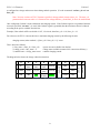
The diagram below shows the charge cutback connections.
D
E
B+
EVSE
Disc1
EVSE
Disc2
Charge
Start
Cell Loop1
Buzzer
12V_Ch
J1772
Pilot
Cell Loop2
GND
GND
J1772
Proximity
Cutback
2 HotInRun
3
GND
F
G
H
CANL
CANH
CANL
CANH
12V_Sw
GND
Figure 10 – Charge Cutback Connections
-9-
J
K
reserved
C
Serial Port
B
reserved
1
A
EVCC v2.1 Firmware
Feb 2015
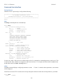
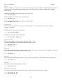
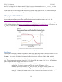
CANBUS CAN is a robust communications protocol designed for automotive applications. CAN uses a two wire interface; the
signals are designated CANH (“CAN high”) and CANL (“CAN low”). Not shown, but assumed, is that each node on
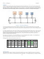
the CAN network is grounded to chassis ground. A CAN network is a daisy-chain, multistation network that should be
terminated on both ends of the string by 120ohm termination resistors. See below for a simple network diagram.
Figure 11 – CAN Network Diagram
CAN wiring should be kept short and the conductors should be twisted. Wiring should be placed away from EMI
(ElectroMagnetic Interference) such as the motor and controller, and parallel runs next to the traction cabling should be
avoided.
In a simple installation, there will be only two nodes on the CAN network: the charger and the EVCC, with a short and
direct connection between the two. In this case, hand-twisted wiring should be fine. In practice, there will be some
amout of “stub” between the CAN network and the device. These stubs should be kept as short as possible, to
minimize reflections and bus interference.
For longer runs, more nodes, or cases where EMI may be an issue, shielded cable is desirable. If a shielded cable is
used, the shield should be connected to chassis ground at a single place.
The figure below shows the connections used for CAN.
D
E
B+
EVSE
Disc1
EVSE
Disc2
Charge
Start
Cell Loop1
Buzzer
12V_Ch
J1772
Pilot
Cell Loop2
GND
GND
J1772
Proximity
Cutback
2 HotInRun
3
GND
F
G
H
CANL
CANH
CANL
CANH
12V_Sw
GND
J
K
reserved
C
Serial Port
B
reserved
1
A
Figure 12 – CAN Connections
CAN Connections Note that the EVCC supports a single CAN interface but brings out two sets of CANH/CANL pins on its connector.
One pair (G1, H1) is wired to a CAN termination resistor in the harness. The CH4100 charger may include an internal
-10-
EVCC v2.1 Firmware
Feb 2015
termination resistor. If so, then connecting a two node system between EVCC and CH4100 charger it is necessary to
simply connect CANH/CANL between the devices.
If other chargers are used, or if more nodes are added to the CAN network, then the CAN network must be wired in a
serial point-to-point fashion between nodes with 120ohm resistors at the ends of the string. Terminal nodes must have
a 120ohm termination resistor. If it is not in the charger, then it should be placed across CANH and CANL as close as
practical to the Signal Connector.
If the EVCC is not a terminal node in the network, the resistor may be removed and the CAN string may be extended.
CAN Protocol The EVCC supports a CAN data rate of 250Kbs and 29-bit CAN addressing. These parameters are not software
configurable, however, both the CH4100 and ELCON chargers require this rate.
The EVCC uses two types of messages to control a CAN enabled charger. The first, from EVCC to Charger, provides
the Charger with the allowable maximum values of charge voltage and charge current, and the second message, from
Charger to EVCC that reports the actual Charging Voltage and Current (in addition to additional charger status).
EVCC/Charger CAN messages are sent approximately twice a second, both from EVCC to Charger and from Charger
to EVCC. If either the EVCC or the Charger does not receive these messages within a short time (on the order of a few
seconds), the charging will terminate.
EVCC/BMS CAN messages communicate pack status. See
-11-
EVCC v2.1 Firmware
Feb 2015
Integration with CAN Enabled BMS, below for the message definitions.
CAN Debugging CAN messages may be lost or corrupted as the result of EMI, stubs that are too long, or improperly terminated cables.
The CAN protocol has sophisticated error detection and recovery mechanisms that allow for automatic retry and
recovery as well as ways of detecting and isolating misbehaving nodes.
In order to facilitate debugging, the EVCC reports CAN error counts in the “show” command.
In addition, there are both high level tracing (“trace charger”) and a low level tracing (“trace can”) facilities to show
CAN message traffic.
-12-
EVCC v2.1 Firmware
Feb 2015
Configuration Serial Port This section describes how to install the serial port drivers and establish serial communications from a host computer
and the EVCC. To use the serial cable, a Virtual Comm Port driver (VCP driver) and a terminal application (or “telnet
client”) is required.
Using a USB to serial bridge is a generic and popular way to connect a host computer to a microcontroller, and the
steps are basically the same regardless of the host computer and operating system. Installation instructions are given
below for Windows XP. See Mac OSX Support, below, for instructions on how to enable the serial port on a MAC
OSX machine. Note that there are good tutorials on how to install the necessary drivers and application software
available on the Internet (for other versions of Windows, MAC, Linux, etc). (Search for “ftdi installation”, “putty
installation”, etc).
Step 1: Install the Virtual Comm Port (VCP) driver on the host computer. The VCP driver is software on the host
computer that emulates a serial port “on top of” a USB connection.
•
•
VCP drivers are available at: www.ftdichip.com/Drivers/VCP.htm.
Installation documentation is available at www.ftdichip.com/Support/Documents/InstallGuides.htm.
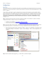
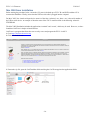
Step 2: Plug in the USB to serial port cable. If the drivers are correctly installed, the host computer will recognize the
new virtual serial port device.; to use this device, is necessary to determine the virtual serial port device name.
•
The virtual serial port device name is of the form “COM<n>”, where n is a small number. This number can be
determined by looking at “Control Panel -> System -> Device Manager -> Ports”. In the example below, it is
“COM15”.
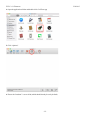
Step 3: Install a terminal console program (e.g., a “telnet client”) on the host computer.
-13-
EVCC v2.1 Firmware
Feb 2015
There are many suitable telnet clients that may be used. For Windows (and linux), one popular choice is
PuTTY, available for download at http://www.chiark.greenend.org.uk/~sgtatham/putty/download.html.
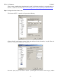
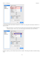
Step 4: Configure the telnet client for use.
The first time PuTTY is opened, it will present the following:
Click on “Serial” in the Category column. Verify that the Speed is 9600, 8 data bits, 1 stop bit. Enter the
Serial Line to connect to (in this case, “COM15”).
Do not hit “Open” just yet. Go back to “Session” by clicking the word “Session” in the Category window.
-14-
EVCC v2.1 Firmware
Feb 2015
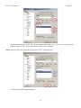
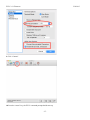
Set the Connection type to Serial. Give the new session a name (in this case “EVCC” in the Saved Sessions
window) and press “Save” to save the session. PuTTY is now configured.
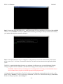
Step 4: Open the comm port. Select the saved session “EVCC” and click Open.
A screen like the following should appear:
-15-
EVCC v2.1 Firmware
Feb 2015
Step 5: Connect the serial cable to the EVCC. Apply power to the EVCC by providing a 12V supply to B+ and GND.
Connect +12V to HotInRun. The EVCC LED should start blinking (assuming the cell loop has not been hooked up
yet), and the following banner should be displayed:
Step 6: At this point, the EVCC may be configured. Configuration is stored in non-volatile memory and retained
across a power cycle. See below, Command Line Interface, for details on what commands are supported and their
syntax.
The EVCC is supplied with defaults, but at the very minimum, it will be necessary to set the Maximum Charging
Voltage (using the command “set maxv”) and Maximum Charging Current (using the command “set maxc”).
WARNING: Lithium batteries can be dangerous if overcharged and it is strongly recommended that the user
check with their battery supplier to determine appropriate charging parameters.
A bringup checklist is provided below. The EVCC also has several diagnostic commands that can be used to verify
proper wiring ( “measure”), to trace can messages (“trace can”), to trace EVCC internal state changes (“trace state”)
and to trace charger operation (“trace charger”).
-16-
EVCC v2.1 Firmware
Feb 2015
LED Operation The LED has the following operating states:
•
•
•
Solid ON
Blink (once per second)
Fast Blink (eight times a second)
– Drive Mode
– Charging
– Cell Loop Error
Charger Support This section gives details on which charger models are supported by the EVCC.
CH4100 See CH4100 Series High Efficiency Intelligent Charger, ThunderStruck User Manual Ver 1.0.2.
http://www.thunderstruck-ev.com/images/ThunderStruckCH4100Manual1.02.pdf
The CAN connections are found on the four pin connector J3. CANL is pin #8 (wired with a blue wire) and CANH is
pin #9 (wired with a green wire). No other connections are required on J3.
There are two versions of CH4100 charger. The frst version has an integrated termination resistor. These chargers are
shipped with the default CH4100 CAN addresses and cannot be reprogrammed. The second version of CH4100
charger does not have an integrated termination resistor and the CAN addresses on these chargers can be
reprogrammed. (The procedure to program the addresses is described below (Programming a CH4100 Charger). Note
that address programming may have been done at Thunderstruck as part of the order).
Each charger requires a unique CAN address. In EVCC terminology a “charger model” refers to both the manufacturer
and its unique CAN address.
CH4100 Charger Models The EVCC defines the following CH4100 charger models:
•
•
•
•
CH4100
CH4100_41
CH4100_42
CH4100_43
- default
The default value for CH4100 chargers is “40”. (Which is to say, the EVCC uses the CAN address 0x18e54024 for
messages TO the charger and 0x18eb2440 FROM the charger to the EVCC).
ELCON ELCON chargers must programmed with the CAN option. In addition, an external ELCON provided CAN module is
needed that terminates the CAN and provides the serial interface for the charger. Only two pins are provided for the
CAN connection: CANH and CANL. The ELCON CAN module does NOT contain an integrated termination resistor.
ELCON Charger Models The CAN addresses of the ELCON chargers are determined by the outboard serial to CAN converter. In order to
change the CAN address, a different serial to CAN module is needed.
The EVCC supports the following ELCON charger models:
•
•
•
•
ELCON
ELCON_E7
ELCON_E8
ELCON_E9
- default
-17-
EVCC v2.1 Firmware
Feb 2015
The default value for ELCON chargers is “E5”. (Which is to say, the EVCC uses the CAN address 1806e5f4 for
messages TO the charger and 18ff50e5 FROM the charger to the EVCC).
Determining the CAN addresses of a Charger If it is necessary to determine the CAN ID of a charger, then power up the chargers individually and use the debugging
command trace can messages to determine what IDs are being used. The chargers will transmit these messages
spontaneously, and it is not necessary to configure the charger in the EVCC to perform this test.
-18-
EVCC v2.1 Firmware
Feb 2015
Bringup Checklist and Troubleshooting Hints EV Installation
1) Connect B+, GND, HotInRun
2) Connect J1772 Proximity, J1772 Pilot, J1772 GND
3) Connect Cutback, if used
Verify Analog Inputs
1) Type “measure” with no parameters to get the expected readings for each analog input. Note that if there is
not a good ground connection between J1772 ground and EV chassis ground that the J1772 readings will be
erratic.
2) Verify Cell Loop, using “measure loop”
a. Disconnect J1772 plug if connected
b. Verify readings with cell loop open and closed.
3) Verify J1772 Proximity, using “measure proximity”
a. Disconnect cell loop, if connected
b. Verify readings with charger plug disconnected, connected, and unlocked.
4) Verify Cutback, if used, using “measure cutback”.
a. Verify readings with cutback enabled and disabled
Verify Charge Start and J1772
1) Connect Cell Loop
2) Plug in J1772 Plug
3) Apply 12V to HotInRun. The EVCC should start charging (LED blinks once per second), 12V_Ch should be
enabled, and the relay in the EVSE should operate after a short delay.
4) Assuming the CAN bus is not connected to the charger yet, the charge cycle should stop after 10-15 seconds.
5) Remove 12V from HotInRun, the EVCC should lose power (LED goes off).
6) Ground Charge start. The EVCC should power up and go into Charge state.
7) For debugging, use “trace state” to verify that the EVCC attempts to start charging if the J1772 plug is in and
the user powers up the EVCC.
Verify Charger and CAN
1) Connect Charger to J1772, connect CAN between Charger and EVCC.
2) Now verify that when a charge cycle is started, that messages are exchanged between EVCC and Charger.
(Use “trace charger” or “trace can” to log the messages).
3) If the pack is not yet connected to the Charger, the charge cycle will stop after a minute.
Systems Test
1) Verify all systems functions.
-19-
EVCC v2.1 Firmware
Feb 2015
Command Line Interface Startup Banner When the EVCC is powered up, it will print the following:
*******************************************************
*
EV Charger Controller v2.1.0
*
*
Thunderstruck Motors / Dilithium Design
*
*******************************************************
evcc>
help The help command prints out command help.
evcc> help
SHow [<>|Version|Config|History]
<>
- status
version
- firmware version
config
- configuration
history
- charge history
SEt [ <>
|BMS
|CHARGER|CHARGER2|CHARGER3|CHARGER4
|MAXV|MAXC|MAXBC|TERMC|TERMT
|FIN_MAXV|FIN_MAXC|FIN_TERMT
|FLT_MAXV|FLT_MAXC|FLT_TERMT
|LINEV_CB|LINEC_CB
]
<>
- ‘set’ help
REset [History]
history
- reset charge history
TRace [CHarger|CANbus|STate|OFF]
<>
- trace toggle ON/OFF
charger
- trace charger messages
canbus
- trace canbus messages
state
- trace EVCC state changes
off
- disable all tracing
MEasure [<>|LOOP|PROXimity|CUTback]
<>
- ‘measure’ help
loop
- measure Cell Loop A/D
proximity - measure J1772 Proximity A/D
cutback
- measure Cutback A/D
In most cases, either a full version or an abbreviated version of a command (or command parameter) can be used. This
is shown in the “help” with the use of uppercase and lowercase letters. For example, the abbreviation for show is sh,
and the abbreviation for show config is sh c.
show The show command displays configured parameters or status.
will be displayed.
If “show” is entered without parameters, current status
In the Drive mode, the EVCC monitors the cell loop and operates the buzzer when the cell loop indicates a pack fault.
evcc> show
state
: DRIVE
-20-
EVCC v2.1 Firmware
cell loop:
proximity:
buzzer
:
CAN Errs :
:
charger :
uptime
:
Feb 2015
OK
EVSE not connected
OFF
TXERRCNT= 0, RXERRCNT= 0
TX Abort= 0, TX LARB= 0, TX MSG ERR= 0
not communicating
0 hour(s), 0 minute(s), 33 second(s)
In the CHARGE mode, the EV is charging.
evcc> show
state
:
cell loop:
proximity:
buzzer
:
CAN Errs :
:
voltage :
current :
charger :
uptime
:
CHARGE
OK
EVSE Connected and locked
OFF
TXERRCNT= 0, RXERRCNT= 0
TX Abort= 0, TX LARB= 0, TX MSG ERR= 0
147.7V
5.9A
306 msgs sent; 320 msgs received
0 hour(s), 3 minute(s), 30 second(s)
Here is an example of CHARGE mode with Cutback is enabled:
evcc> show
state
:
cell loop:
proximity:
cutback :
buzzer
:
voltage :
current :
charger :
uptime
:
CHARGE
OK
EVSE Connected and locked
enabled
OFF
146.5V
1.9A
349 msgs sent; 364 msgs received
0 hour(s), 4 minute(s), 51 second(s)
show version The version command displays firmware version number and build date.
evcc> show version
version :
v2.0; Sep 23 2014 12:04:16
evcc>
show config The show config command displays configuration parameters.
evcc> show
bms
charger
maxv
maxc
termc
termt
evcc>
config
: loop
: CH4100
:
40.0V
:
2.0A
:
0.2A
:4320 min
These are
• bms
• charger
- the bms type (cell loop, can, or both)
- the configured charger model
-21-
EVCC v2.1 Firmware
•
•
•
•
•
•
•
•
•
•
•
•
•
•
charger2-4
maxv
maxc
maxbc
termc
termt
fin_maxv
fin_maxc
fin_termt
fln_maxv
fln_maxc
fln_termt
linev_cb
linec_cb
Feb 2015
- (present if configured) model types of chargers2-4
- maximum charging voltage (in Volts). This is provided to the charger.
- maximum charging current (in Amps). This is provided to the charger.
- (present if configured) maximum balance cutback current
- terminating charging current (in Amps). See text.
- maximum charging time (in minutes). See text.
- (present if configured) finishing charge voltage (for SLA charging)
- (present if configured) finishing charge current (for SLA charging)
- (present if configured) finishing charge current (for SLA charging)
- (present if configured) float charge voltage (for SLA charging)
- (present if configured) float charge current (for SLA charging)
- (present if configured) float charge current (for SLA charging)
- (present if configured) line voltage if cutback is enabled
- (present if configured) line current if cutback is enabled
show history The show history command displays data about the last sixteen charge cycles. See also reset history, below.
In the first example, the system has no charge history yet.
evcc> show history
no charge history
The next example shows charge history, with different “termination reasons”. The termination reason contains the
reason that the charge cycle stopped. In this example, in the most recent charge attempt, the user disconnected the
J1772 plug one minute after charging started. (EVSE disc, 1 mins). The previous attempt (“-1”) shows a normal
charge completion with a charge time of 214 minutes and includes the number of watt hours delivered.
Note that the voltage and current measurements are provided by the charger in the CAN message to the EVCC. The
EVCC does not measure pack voltage or current.
evcc> show history
|
term
| charge |
watt | maximum| maximum| ending|
num | reason |
time | hours | voltage| current| current|
---------------------------------------------------------------last | EVSE disc|
1 mins|
7Wh| 148.9V |
7.9A |
7.9A |
- 1 |
normal | 214 mins| 3249Wh| 152.9V |
7.9A |
0.5A |
- 2 | EVSE disc|
1 mins|
0Wh| 144.8V |
0.0A |
0.0A |
- 3 | comm err |
0 mins|
0Wh|
0.0V |
0.0A |
0.0A |
evcc>
The full set of “term reason” codes is:
• EVSE disc
- J1772 charge plug became unlocked while charging
• cell loop
- a cell loop fault or HVC condition was detected
• comm err
- communications error with the charger
• pack disc
- no pack was detected
• timeout
- the maximum charge time was reached
• normal
- normal completion (charge current is less than terminating charging current)
• fintimeout - finishing charge timeout
• fin normal - normal termination of finishing charge
• flttimeout - float charge timeout
-22-
EVCC v2.1 Firmware
Feb 2015
The format of the charge history is modified to show the contribution of each charger when multiple chargers are
configured.
evcc> show history
|
term
| charge |
|
watt | maximum| maximum| ending|
num | reason |
time | charger | hours | voltage| current| current|
------------------------------------------------------------------------last | EVSE disc|
2 mins|ch4100
|
6Wh| 127.8V |
2.2A |
0.0A |
|ch4100_42|
6Wh| 127.5V |
2.0A |
0.0A |
|TOTAL
|
12Wh| 127.8V |
4.2A |
0.0A |
set This command sets the configurable parameters. For voltage and current, whole numbers (145) or decimal numbers
(145.2) can be entered. The EVCC supports one decimal digit of precision.
set <> Using the set with no parameters will option will print additional help for the “set” command.
evcc> set
SEt [ <>
|BMS
|CHARGER|CHARGER2|CHARGER3|CHARGER4
|MAXV|MAXC|MAXBC|TERMC|TERMT
|FIN_MAXV|FIN_MAXC|FIN_TERMT
|FLT_MAXV|FLT_MAXC|FLT_TERMT
|LINEV_CB|LINEC_CB
]
<>
- ‘set’ help
bms configuration
set bms [NONE|LOOP|CAN|LOOP,CAN]
charger configuration
<chargern>
- [CHARGER|CHARGER2|CHARGER3|CHARGER4]
<model>
- [ CH4100|CH4100_41|CH4100_42|CH4100_43
|ELCON |ELCON_E7 |ELCON_E8 |ELCON_E9
set <chargern> <model> - defines <chargern>
set <chargern> NONE
- deletes <chargern>
set <chargern> <type> PROGRAM - programs CH4100 CAN IDs
BULK charge parameters
set maxv <v>
- maximum charge voltage
set maxc <a>
- maximum charge current
set maxbc <a>
- maximum balancing current
set termc <a>
- charge termination current
set termt <m>
- charge termination timeout
SLA charge parameters
set fin_maxv <v> - finishing charge voltage
set fin_maxc <a> - finishing charge current
set fin_termt <m> - finishing charge termination timeout
set flt_maxv <v> - float charge voltage
set flt_maxc <a> - float charge current
set flt_termt <m> - float charge termination timeout (0=no timeout)
Service cutback
set linev_cb <v> - cutback line voltage
set linec_cb <a> - cutback line current
-23-
EVCC v2.1 Firmware
Feb 2015
set bms This sets the BMS type. The EVCC can use a cell loop and/or up to four CAN BMSs. The BMS determines whether a
cell in the pack has exceeded the High Voltage Cutoff, Low Voltage Cutoff, or Balance Voltage Cutoff. Multiple
BMSs cabe bve
The following example just sets the bms type to be the cell loop.
evcc> set bms loop
The next example sets the bms to use CAN messaging.
evcc> set bms can
The next example sets the bms to use loop and CAN messaging.
evcc> set bms loop, can
set charger<n> This sets the charger type. The first charger is named “charger”. Chargers 2 through 4 are named “charger2”,
“charger3”, “charger4”.
The following command sets a single charger
evcc> set charger CH4100
The following command sets a second charger
evcc> set charger2 CH4100_42
set maxv, set maxc The command set maxv sets the maximum charging voltage, in Volts.
The command set maxc sets the maximum charging current, in Amps.
evcc> set maxv 155.0
evcc> set maxc 8.5
set maxbc This sets the maximum balancing charging current, in Amps. This option is only possible if a CAN BMS is used and it
sends a “BVC threshold exceeded” indication to the EVCC.
evcc> set maxbc .7
set termc This sets the termination charging current, in Amps. If the current drops below this setpoint then the charging stops.
evcc> set termc .5
set termt This sets the maximum charging time, in minutes.
evcc> set termt 480
set linev_cb, set linec_cb This sets the maximum line voltage and line current available when the Cutback input is enabled.
evcc> set linev_cb 110
evcc> set linec_cb 12
-24-
EVCC v2.1 Firmware
Feb 2015
set fin_maxv, set fin_maxc, set fin_termt These commands are used to define the “finishing charge” phase voltage, current, and charge time for Sealed Lead
Acid battery charging. See below, Finishing Charge for examples of use.
set flt_maxv, set flt_maxc, set flt_termt These commands are used to define the “float charge” phase voltage, current, and charge time for Sealed Lead Acid
battery charging. See below, Float Charge for examples of use.
reset history The reset history command resets the charge history.
evcc> reset history
charge history has been reset
evcc>
trace The trace command enables various forms of message or state tracing. These commands show a timestamp (uptime)
and can be useful for logging or debugging. CHARGER, STATE, and CANBUS tracing may be independently
enabled.
Trace configuration is stored in EEPROM and is present after reboot.
trace <> Trace with no parameters toggles state trace on and off.
trace charger The trace charger command displays messages from the charger. This trace also shows the current number of
charging watts and the accumulated WattHours of charge.
evcc> trace charger
charger tracing is now ON
evcc> 00:08:22.7 V=148.6, A= 7.9, W=1173, Wh= 0.96
00:08:23.1 V=148.6, A= 7.9, W=1173, Wh= 1.12
00:08:23.6 V=148.6, A= 7.9, W=1173, Wh= 1.28
00:08:24.1 V=148.6, A= 7.9, W=1173, Wh= 1.45
00:08:24.6 V=148.6, A= 7.9, W=1173, Wh= 1.61
00:08:25.1 V=148.6, A= 7.9, W=1173, Wh= 1.77
00:08:25.6 V=148.6, A= 7.9, W=1173, Wh= 1.93
00:08:26.1 V=148.6, A= 7.9, W=1173, Wh= 2.08
00:08:26.6 V=148.6, A= 7.9, W=1173, Wh= 2.25
00:08:27.1 V=148.6, A= 7.9, W=1173, Wh= 2.41
00:08:27.6 V=148.6, A= 7.9, W=1173, Wh= 2.57
00:08:28.0 V=148.6, A= 7.9, W=1173, Wh= 2.73
00:08:28.6 V=148.6, A= 7.9, W=1173, Wh= 2.89
00:08:29.0 V=148.6, A= 7.9, W=1173, Wh= 3.05
00:08:29.6 V=148.9, A= 7.9, W=1176, Wh= 3.22
trace canbus The trace canbus command displays canbus messages to and from the charger. Each line gives a timestamp, the
originator of the message (if known), the CAN ID and CAN message contents, in hexadecimal.
evcc> trace can
canbus tracing is now ON
00:01:27.3
evcc: 18e54024 fc c8 00 6c 0c ff ff ff
00:01:27.4 ch4100_41: 18eb2441 01 fd 00 00 80 0c 38 ff
-25-
EVCC v2.1 Firmware
00:01:27.5
00:01:27.8
00:01:27.9
00:01:27.9
00:01:28.3
00:01:28.4
00:01:28.5
ch4100
:
evcc:
ch4100_41:
ch4100
:
evcc:
ch4100_41:
ch4100
:
Feb 2015
18eb2440
18e54024
18eb2441
18eb2440
18e54024
18eb2441
18eb2440
00
fc
01
00
fc
01
00
fc
c8
fd
fc
c8
fd
fc
4b
00
00
4b
00
00
4b
04
6c
00
04
6c
00
04
80
0c
80
80
0c
80
80
0c
ff
0c
0c
ff
0c
0c
4a
ff
38
4a
ff
38
4a
ff
ff
ff
ff
ff
ff
ff
trace state The trace state command displays internal EVCC state transitions. It shows whether the EVCC is in DRIVE,
CHARGE, or CHARGE/WARMDOWN, as well as the state of the J1772 charge plug.
Here is an example of state trace output that shows the charger plug being plugged in and unplugged.
evcc> trace state
state tracing is now ON
evcc> 00:06:53.4 old state=DRIVE, new state=CHARGE, j1772=LOCKED, term rsn=0
00:07:16.9 old state=CHARGE, new state=CHARGE/WARMDOWN, j1772=WAITING FOR DISC, term
rsn=EVSE UNLOCKED
00:07:17.2 old state=CHARGE/WARMDOWN, new state=CHARGE/WARMDOWN, j1772=DISCONNECTED,
term rsn=0
00:07:28.9 old state=CHARGE/WARMDOWN, new state=DRIVE, j1772=DISCONNECTED, term rsn=0
trace off The trace off command turns off all tracing.
evcc> tr off
all tracing is now OFF
measure The measure command is used to verify the A/D inputs. When this command is issued, the EVCC will repeatedly
measure and print the value of an analog input. The command will run for 30 seconds and then automatically turn
itself off. Alternately, the user can stop the command by typing any character.
The measure command with no parameters will display the expected values of the A/D inputs.
evcc> measure
This command repeatedly shows an analog input for 30 seconds.
Press any key to stop display
The following values are expected
loop
- Cell Loop A/D
> 2.5V - OK
proximity - J1772 Proximity A/D
> 4.0V - disconnected
> 2.5V - connected
else
- locked
cutback
- Cutback A/D
< 4.0V - enabled
evcc>
measure loop The measure loop command gives a real time measurement of the cell loop.
evcc> measure loop
-26-
EVCC v2.1 Firmware
Feb 2015
evcc> Loop A/D= 4.97V
Loop A/D= 4.97V
Loop A/D= 4.97V
Loop A/D= 4.97V
Loop A/D= 4.97V
measure cutback The measure cutback command gives a real time measurement of the cutback input.
evcc> me cutback
evcc> Cutback A/D= 4.99V
Cutback A/D= 4.99V
Cutback A/D= 4.99V
Cutback A/D= 4.99V
Cutback A/D= 4.99V
measure proximity The measure proximity command gives a real time measurement of the J1772 proximity input.
In the example given below, both the measure proximity and trace state commands are enabled. Initially the J1772
charge plug is connected, then it becomes unlocked, and then finally, removed.
evcc> me prox
evcc> Proximity A/D= 1.50V
Proximity A/D= 1.50V
Proximity A/D= 1.50V
00:06:07.5 old state=CHARGING, new state=WARMDOWN, j1772=WAITING FOR DISC, term
rsn=EVSE UNLOCKED
Proximity A/D= 2.76V
Proximity A/D= 2.76V
Proximity A/D= 4.45V
00:06:12.0 old state=WARMDOWN, new state=WARMDOWN, j1772=DISCONNECTED, term rsn=0
Proximity A/D= 4.45V
Proximity A/D= 4.45V
-27-
EVCC v2.1 Firmware
Feb 2015
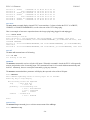
Configuring the EVCC with Multiple Chargers Up to four chargers can be used in parallel for faster charging. A logical picture is shown in the diagram below.
Figure 13 - Multiple Chargers - System Diagram
Note that there is a single J1772 interface for line power which feeds all chargers. The chargers are in parallel and they
charge a single pack. All chargers are placed on the CANBUS. There is a single EVCC and it communicates with the
chargers independently. (Also shown on the CANBUS is a CAN enabled BMS, optionally present).
There are several design considerations when installing multiple chargers.
•
•
•
Line power. Two chargers require more power than a single charger. One must verify that adequate line
power is available.
CAN wiring and addressing. With more CAN nodes, the CAN wiring is no longer simply point to point and
installation must be done with care. Each charger requires a unique CAN ID.
EVCC configuration. Each charger must be explicitly configured in the EVCC.
Line Power The EVCC assumes that the service can provide 220V at 30A. Note that the cutback feature, if enabled, will limit line
voltage and current to configured limits.
Power calculations are needed to make sure that there is sufficient power available to power all chargers. A 220V /
30A circuit has 6600Watts available. Two 2.5Kw chargers running at full power can be placed on the line, but three
chargers cannot. (In contrast, a 110V / 15A circuit only has 1650Watts available).
CAN Wiring and Addressing See the section on CANBUS, above, for general guidelines. When installing multiple chargers, care must be taken that
termination resistors are properly placed. Keep in mind that some chargers have a termination resistor installed in the
-28-
EVCC v2.1 Firmware
Feb 2015
charger, and so that charger must be at the end of the CAN string. Keep wiring stubs as short as possible. Shielded
cable may be required.
Each charger must have a unique CAN address. In EVCC terminology, the “charger model” determines both the
charger manufacturer as well as the charger CAN address. The following sections describe what charger models are
supported. See Charger Support for the charger models supported.
EVCC Configuration The EVCC supports up to four chargers (named: charger, charger2, charger3, and charger4). Chargers are
defined in the EVCC using the set charger command. When a charger is configured, it is set to a “charger model”,
which indicates both the manufacturer and its CAN address. It is possible to have chargers from multiple
manufacturers (e.g., one ELCON and one CH4100) at the same time.
The following example defines a single charger and sets its model to ch4100:
evcc> set charger ch4100
evcc> show config
bms
: loop
charger : ch4100
maxv
: 158.0V
maxc
:
12.0A
termc
:
0.5A
termt
:4320 min
evcc>
This example defines a second charger, and sets its model to ch4100_42.
evcc> set charger2 ch4100_42
evcc> show config
bms
: loop
charger : ch4100
charger2 : ch4100_42
maxv
: 158.0V
maxc
:
12.0A
termc
:
0.5A
termt
:4320 min
evcc>
A charger can be deleted by setting the model to “none”.
evcc> set charger2 none
Programming a CH4100 Charger This section describes how to set the CAN addresses of a programmable CH4100 charger. If this procedure is
performed on a charger that does not support it, it will have no effect.
For this procedure, the charger can either be directly connected to mains power, or can be installed in the vehicle and
the J1772 charge plug can be used to supply line power. When doing this procedure, insure that only one charger can
receive line power.
In this example, we want to define a second charger as model ch4100_42. If the charger is already programmed as
model ch4100_42, then it would only be necessary to use the command set charger2 ch4100_42. In order to program
the charger, it is necessary to use the program keyword.
To do this, power up the EVCC by keyswitch. Then type the following command:
-29-
EVCC v2.1 Firmware
Feb 2015
evcc> set charger2 ch4100_42 program
The EVCC will then print
***
***
CH4100 PROGRAMMING
***
*** WARNING: This command changes the CAN IDs of a CH4100 charger ***
*** ONLY ONE CH4100 charger should be powered up at this time
***
***
Proceed [Y/N] ?
If you type "y", the evcc then prints
Programming the charger ...
and then 5-10 seconds later it prints
Programming the charger ... done.
The charger must now be power cycled.
evcc>
At that point the new charger will be programmed to CH4100_42 and it will be configured in the evcc as "charger2".
Charging with Multiple Chargers When charging with multiple chargers, maxc is divided by the number of chargers and given to each charger. So here
is an example of charger tracing when maxc is set to 12A. Note that 6A goes to both ch4100 and ch4100_42. Note
that “trace charger” reports the status of the charger … and that voltage, current, watts, and watt hours may be slightly
different.
evcc> trace charger
charger tracing is now
00:10:28.8 ch4100_42:
00:10:28.9 ch4100
:
00:10:29.3 ch4100_42:
00:10:29.3 ch4100
:
00:10:29.8 ch4100_42:
00:10:29.9 ch4100_42:
00:10:29.9 ch4100_42:
00:10:30.0 ch4100_42:
00:10:30.0 ch4100_42:
00:10:30.1 ch4100_42:
00:10:30.2 ch4100_42:
00:10:30.3 ch4100_42:
00:10:30.3 ch4100_42:
00:10:30.4 ch4100_42:
00:10:30.5 ch4100_42:
ON
V=126.0,
V=126.3,
V=126.6,
V=126.6,
V=127.2,
V=127.2,
V=127.2,
V=127.2,
V=127.2,
V=127.2,
V=127.2,
V=127.2,
V=127.2,
V=127.2,
V=127.2,
A=
A=
A=
A=
A=
A=
A=
A=
A=
A=
A=
A=
A=
A=
A=
5.8,
5.9,
5.7,
5.8,
5.9,
5.9,
5.9,
5.9,
5.9,
5.9,
5.9,
5.9,
5.9,
5.9,
5.9,
W=730,
W=745,
W=721,
W=734,
W=750,
W=750,
W=750,
W=750,
W=750,
W=750,
W=750,
W=750,
W=750,
W=750,
W=750,
-30-
Wh=
Wh=
Wh=
Wh=
Wh=
Wh=
Wh=
Wh=
Wh=
Wh=
Wh=
Wh=
Wh=
Wh=
Wh=
0.10
0.09
0.19
0.19
0.30
0.31
0.33
0.34
0.36
0.37
0.39
0.40
0.42
0.43
0.44
EVCC v2.1 Firmware
Feb 2015
Integration with CAN Enabled BMS The EVCC can be used with a CAN enabled Battery Management System. The following functions are supported:
•
•
•
High Voltage Cutoff (HVC) Detection. In this case, the BMS detects that at least one cell has exceeded its
programmed High Voltage Cutoff limit. If this occurs, the BMS sends a message to the EVCC which causes
the EVCC to stop charging.
Balance Voltage Cutoff (BVC) Detection. In this case, the BMS detects that at least one cell has exceeded its
programmed Balance Cutoff limit. If this occurs, the BMS sends a message to the EVCC that it should reduce
its charging current to the maximum balancing current (maxbc). Lowering the charging current allows current
bleeding cell balancers to prevent additional charging of the highest cells in the pack.
Low Voltage Cutoff (LVC) Detection. In this case, the BMS detects that at least one cell voltage is less than
its programmed Low Voltage Cutoff limit. If this occurs, the BMS sends a message to the EVCC which causes
the EVCC to operate the buzzer.
BMS Operation The programming of the actual HVC, BVC, and LVC are done in the BMS. The BMS must determine if any cell in
the pack meets these conditions and if so, it sets a bit associated with each of these conditions. This information is sent
in a message from the BMS to the EVCC; the message must be periodically sent at least once a second.
/*
* The EVCC supports 250Kbps CAN data rate and 29 bit identifiers
*/
#define uint8
unsigned char
/*
* BMS->EVCC message Identifier
*/
#define BMS_EVCC_STATUS_IND
#define BMS_EVCC_CELL_HVC_FLAG
#define BMS_EVCC_CELL_BVC_FLAG
#define BMS_EVCC_CELL_LVC_FLAG
0x01dd0001
0x01
0x02
0x04
/* set if a cell is > HVC */
/* set if a cell is > BVC */
/* set if a cell is < LVC */
/*
* BMS->EVCC message body
*/
typedef struct tBMS_EVCC_StatusInd
{
uint8 bBMSStatusFlags;
/* see bit definitions above */
uint8 bReserved;
/* reserved, set to 0
*/
} tBMS_EVCC_StatusInd;
Note that although the CAN message only has a 2 byte message body, up to 8 bytes may be sent to the EVCC. These
bytes should be set to 0 if so. In v2.1 firmware, the EVCC will ignore additional message bytes.
EVCC Operation In order to use the CAN interface with the BMS, it must be configured in the EVCC, using the set bms command. It is
possible to configure the EVCC to only use LOOP, only use CAN, or use both LOOP and CAN.
If the EVCC is configured to only use LOOP, then if the loop circuit is closed then the pack is error free; if the loop
circuit is open, HVC is assumed if in CHARGE mode and LVC is assumed if in DRIVE mode.
If the EVCC is configured to use only CAN, then the pack status is taken from the BMS_EVCC_STATUS_IND
message. Note that the message also supports the BVC condition (which the loop does not). If that is reported, then
-31-
EVCC v2.1 Firmware
Feb 2015
the EVCC will drop back into balance cutback. If there is a message timeout and BMS_EVCC_STATUS_IND does
not arrive, then this is treated as a loop open (e.g., HVC and LVC are assumed).
If both LOOP and CAN are configured then an error results if either input reports an error. So, in this case, charging
will stop if the loop opens, the CAN message indicates HVC, or there is a CAN message timeout.
Charging Lead Acid Batteries Lead Acid Batteries require a multi-stage charging algorithm. The terminology to describe the algorithms varies in the
industry and between manufacturers. Here we follow the documentation and requirements from Trojan. See
http://www.trojanbattery.com/pdf/TRJN0109_UsersGuide.pdf.
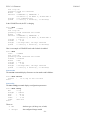
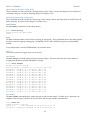
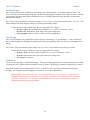
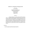
As an example consider a EV pack that consists of 12 Trojan 30XHS deep cycle flooded batteries, charging at 25°C
(77°F). See the following from http://www.trojanbattery.com/pdf/TRJN0111_ProdSpecGuide.pdf. For reference, the
C20 rating of 30XHS batteries is 130AH (this number comes in handy below).
Figure 14 – Flooded Lead Acid Charging Profile (Trojan)
Bulk Charge The first phase of charging is the Bulk Charge phase. (Note that the Bulk Charge phase is sometimes thought of as two
phases: a constant current phase and a constant voltage phase). The EVCC supports this phase by the parameters maxv
and maxc. This phase is used by both Lithium and Lead Acid chemistries (including flooded, AGM, and Gel).
See Figure 14, above. For flooded cells, the Bulk Charge phase brings the cells to over 90% state of charge. For its
cells, Trojan recommends a maximum voltage of 2.35 to 2.45v per cell, and a current of 10-13% C20. The bulk charge
phase completes when the charging current drops to 1-3% of C20.
In the example of twelve 30XHS cells, here are suggested EVCC settings:
• maxv=172.8: The charging voltage would be 2.4v * 6 cells * 12 batteries = 172.8v.
• maxc=13: Since 30XHS cells have a C20 rating of 130AH, the charging current would be 13A.
• termc=2.6: The guidelines are 1-3% of C20. 2.6A is 2% of the C20 rating of 30XHS.
• termt=480: (10 hours). This parameter is a failsafe; the actual time of charge will depend on depth of
discharge. In 10 hours, this would allow 13A*10H =130 AH to be delivered to the batteries.
-32-
EVCC v2.1 Firmware
Feb 2015
Finishing Charge For Lead Acid batteries, the second phase of charging is the “finishing charge” or “absorption charge” phase. The
EVCC will only enter the finishing charge phase if the bulk charging phase completes successfully, if termc is reached.
(In particular, if the bulk charge phase terminates because of a charging timeout [termt], then this is considered an
abnormal termination).
For its cells, Trojan recommends a maximum voltage of 2.45 to 2.79v per cell, and a current limit of 1-3% of C20. This
phase completes when the charging voltage rises to the target finishing voltage.
In the example of twelve 30XHS cells, here are suggested EVCC settings:
• fin_maxv=187.2: The finishing voltage would be 2.6v * 6 cells * 12 batteries = 187.2v.
• fin_maxc=2.6: Note that this is the same as the termc setting above.
• fin_termt=480: (2 hours). termt is a failsafe on this charging phase.
Float Charge Once Lead Acid batteries are charged, they may be kept on a “float charge” or “trickle charge”. Lead Acid batteries
have a relatively high self-discharge rate and this phase keeps them topped up if the EV sits for an extended period of
nonuse.
For its cells, Trojan recommends a float voltage of 2.2v per cell. A current limit is not explicitly specified.
In the example of twelve 30XHS cells, here are suggested EVCC settings:
• flt_maxv=158.4: The float voltage would be 2.2v * 6 cells * 12 batteries = 158.4v.
• flt_maxc=2.6: Note that this is the same as the termc setting, above.
• flt_termt=0: No timeout
Limitations The EVCC does not support “equalization charge”. This type of charging purposely overchargers the batteries in order
to balance the cells. Higher charge cells bubble off excess charge as hydrogen gas, and lower charged cells “catch up”.
Temperature sensors are not supported in the EVCC, so the EVCC does not perform temperature compensated
charging. The examples assumes charging at a constant 25°C in a well ventilated area.
DISCLAIMER: This is an example only. These instructions do not cover all details or variations in the
equipment and do not claim to provide for every possible contingency met in connection with installation,
operation, or maintenance. It is strongly recommended that the user check with their battery supplier to
determine appropriate charging parameters.
-33-
EVCC v2.1 Firmware
Feb 2015
Mac OSX Driver Installation Before starting the procedure below, ensure the 12V power is hooked up to EVCC B+ and GND, and that 12V is
connected to HotInRun. Finally, insure that the USB to serial cable is plugged into the computer.
For MAC OS X, the virtual serial port device name is of the form “usbserial-<sn> where <sn> is the serial number of
the USB to serial device. An example of what the name of the EVCC would look like is the following: usbserialFTGDTR8M.
The MAC OSX distribution includes the applications “terminal” and “screen”, which may be used. However, we have
found that CoolTerm is simpler to install and use.
CoolTerm is a program that allows the user to easily access and program the EVCC via OS X.
1. Go to http://freeware.the-meiers.org
2. Click download for mac
3. Extract the .zip file, open the CoolTermMac folder and drag the CoolTerm app into the applications folder.
-34-
EVCC v2.1 Firmware
Feb 2015
4. Open the applications folder and double click CoolTerm.app
5. Click “Options”
6. Ensure the “baudrate” is set to 9600 (which should already be set by default).
-35-
EVCC v2.1 Firmware
Feb 2015
7. Click the drop down menu and select “usbserial-<sn>” where <sn> is the specific serial number of the EVCC as
discussed earlier.
! Note: The usbserial-<sn> will not show up in the drop down menu if the USB is not plugged in prior to
starting the program. If this occurs, exit CoolTerm, plug in the USB cable and restart CoolTerm.
8. Still in “Options” go to the left hand column and click “terminal.” Then change the window to match the settings
below.
-36-
EVCC v2.1 Firmware
Feb 2015
9. Click “Connect”
10. Press the “return” key, the EVCC command prompt should come up.
-37-
EVCC v2.1 Firmware
Feb 2015
! Note: Although the operation of the serial port is very similar to the Windows examples, above, there is
one important difference. Windows keyboards generate an ASCII “DEL” character when a “delete” is
pressed. MAC keyboards generate an ASCII “BS” character. Current EVCC firmware only interprets the
DEL key and the MAC “delete” key may not work as expected. However, the ASCII “DEL” character can
usually be generated by MAC keyboards (look for another “delete” key with an “x” or try pressing FNDEL).
-38-
EVCC v2.1 Firmware
Feb 2015
Warrantee and Support The Thunderstruck return policy is available at http://www.thunderstruck-ev.com/return-policy.html.
The EV Charger Controller is warranted to be free from defects in components and workmanship under normal use and
service for a period of 1 year.
When failing to perform as specified during the warranty period we will undertake to repair, or at our option, replace
this product at no charge to its owner, provided the unit is returned undamaged and shipping prepaid, to Thunderstruck
motors.
The product is intended for non-commercial use by hobbyists. The warranty does not apply to defects arising from
miswiring, abuse or negligence, accidents, opening the enclosure, or reverse engineering. Thunderstruck Motors and
Dilithium Design shall not be responsible for any incidental or consequential damages.
Thunderstruck Motors and Dilithium Design reserve the right to make changes or improvements in design or
manufacturing without assuming any obligation to change or improve products previously manufactured and / or sold.
For general support and warrantee issues, contact
[email protected]
For errors in this document, or comments about the product, contact
[email protected]
Document History Rev 2.0.0
Rev 2.0.1
Rev 2.0.2
Rev 2.1.0
Sept 22, 2014
Sept 30, 2014
Nov 10, 2014
Feb 25, 2015
In review
Production Version
Added Mac OSX serial support
Added support for v2.1 features, including: multiple chargers,
Lead Acid, CAN BMS integration. Cutback configuration was changed.
-39-