1
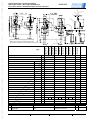
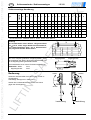
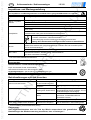
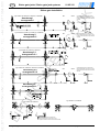
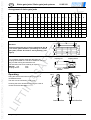
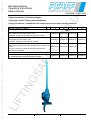
Betriebsanleitung Operating Instructions Mode d’emploi 01.05.312 - 01.01.2004 Schleusenwinden / Schleusenanlagen Sluice-gate Jacks / Sluice-gate Installations Crics pour vannes / Installations se composant de crics pour vannes d‘écluses Hublast / capacity / capacité [t] 1,5 3 5 10 Type Schleusenwinde mit Sicherheitsfederkurbel Sluice-gate jack with safety spring crank Crics pour vanne avec manivelle de sécurité à ressort Schleusenwinde mit Sicherheitskurbel Sluice-gate jack with safety crank Crics pour vanne avec manivelle de sécurité Schleusenwinde mit Sicherheitsfedersperre und Steckkurbel Sluice gate-jack with safety spring locking device and plug-in crank Cric pour vanne avec cliquet de sécurité à ressort avec manivelle embrochable 030029130 030030139 030031135 - 030029017 030030015 030031011 030032018 030029140 030030140 030031140 - Sonderausführung / special design / modèle spécial 030029999 030030999 030031999 030032999 Schleusenanlage / Sluice-gate Installation / Installations se composant de crics pour vannes d’écluses 030082139 030083135 030084131 030085081 technische Änderungen vorbehalten design changes under reserve changements techniques sous réserve Schleusenwinden / Schleusenanlagen Sluice-gate Jacks / Sluice-gate Installations Crics pour vannes / Installations pour vannes d‘écluses 01.05.312 Maßblatt / Dimension sheet / Page du dimension 17 Ø14 17 Ø14 *) * ) Hublast / capacity capacité Hub / lift / course [mm] Zahnstangenlänge/ rack length/ longueur de la crémaillère [mm] AxB C D E F G H I J K L M N O P R S T U X Y [mm] 1) 2) 3) Sicherheitsfederkurbel Sicherheitskurbel Sicherheitsfedersperre mit Steckkurbel technische Änderungen vorbehalten [mm] [mm] [mm] [mm] [mm] [mm] [mm] [mm] [mm] [mm] [mm] [mm] [mm] [mm] [mm] [mm] [mm] [mm] [mm] [mm] 2) 030032018 030031140 3) 030031011 2) 030031135 1) 030030140 3) 030030015 2) 030030139 1) 030029140 3) Type 030029017 2) 030029130 1) Unterkante Gehäuse bei eingezogener Zahnstange *) Bottom edge of housing with retracted toothed rack *) Bord inférieur du boîtier quand la cremaillère est remontée *) *) *) 1,5 3 5 10 800 800 900 1000 1200 1250 1350 1550 35x25 45x30 50x40 60x50 140 160 145 165 85 60 45 65 125 204 189 235 78 92 100 112 175 230 260 320 310 395 400 480 33,5 39,5 51 59 43,3 53,1 69,5 88,3 121 138 81 84 230 230 230 290 90 90 90 115 153 158 173 183 52,5 55 61 66 52,5 55 64 70 7 7 7 7 76,5 85,5 88 100 100,5 108,5 120 140 86 113 136 94 121 144 105 132 155 185 130 130 130 250 250 250 250 300 safety spring crank safety crank spring loaded safety lock with plug-in crank design changes under reserve manivelle de sécurité à ressort manivelle de sécurité linguet de sécurité à ressort avec manivelle embrochable changements techniques sous réserve = = = Sifeku Siku Sifespe Seite / page 2 Deutsch Schleusenwinden / Schleusenanlagen Vor Inbetriebnahme die Betriebsanleitung aufmerksam lesen. Sicherheitshinweise beachten. Dokument aufbewahren! Bestimmungsgemäße Verwendung Das Schleusenwinde ist eine handbetriebene Zahnstangenwinde zum Öffnen und Schließen von Schützentafeln und Schiebern. Nicht geeignet für Einsatz in explosionsgefährdeten Räumen. Maschineller Antrieb verboten! Nicht für Dauerbetrieb zugelassen. Änderungen an der Schleusenwinde, sowie das Anbringen von Zusatzgeräten, sind nur mit unserer ausdrücklichen schriftlichen Genehmigung erlaubt. Technische Daten und Funktionsbeschreibung beachten! Unfallverhütungsvorschriften Es sind jeweils die im Einsatzland gültigen Vorschriften zu beachten1) in Deutschland z.Zt.: UVV BGV D 8 Winden- Hub- und Zuggeräte, DIN 7355 Stahlwinden, EG Richtlinie 98/37/EG 1) in der jeweils gültigen Fassung Sicherheitshinweise Bedienung, Montage und Wartung nur durch: Ö beauftragte Ö eingewiesene Ö mit den Vorschriften vertrauten Personen 01.05.312 Das Befördern von Personen, sowie der Aufenthalt im Gefahrenbereich ist verboten. Aufenthalt unter gehobener Last verboten. Die Last nie in gehobenem Zustand ungesichert schweben lassen. Nie in bewegliche Teile greifen. Mängel sind sofort sachkundig zu beheben. Auf die Schleusenwinde dürfen nur senkrechte, mittig in Zahnstangenrichtung verlaufende Kräfte wirken. Auf die Zahnstangenwinde dürfen keine Seitenkräfte wirken. Auftretende Seitenkräfte müssen bauseitig aufgenommen werden. Bremsmechanismus nicht fetten oder ölen. Kurbelkraft nicht überschreiten. Tragfähigkeit entsprechend techn. Datenblatt, (Typenschild) nicht überschreiten. Vor Erstinbetriebnahme durch Sachkundigen prüfen. Täglich bzw. vor jedem Einsatz prüfen – Bremsfunktion – Sichtprüfung der Sicherheitsteile wie Kurbel, Sperrklinke, Befestigung usw. – Tragkonstruktion Mindestens 1x jährlich UVV Prüfung durch Sachkundigen durchführen. Inspektions- und Wartungsintervalle unbedingt einhalten. Nur original Zubehör- und Ersatzteile verwenden, sichere Funktion ansonsten nicht gewährleistet. Hub Hub je Kurbelumdrehung Kurbelkraft Gewicht [daN] [kg] - 1200 800 14 28 18 X - 1200 800 14 28 18 - - X 1200 800 14 28 18 20 X - - 1250 800 8,6 28 25 30 20 - X 1250 800 8,6 28 25 030030140 30 20 - - X 1250 800 8,6 28 25 030031135 50 30 X - - 1350 900 4,5 28 32 030031011 50 30 - X - 1350 900 4,5 28 32 030031140 50 30 - - X 1350 900 4,5 28 32 030032018 100 60 - - X 1550 1000 3,2 44 56 [kN] [kN] 030029130 15 10 X - 030029017 15 10 - 030029140 15 10 030030139 30 030030015 geeignet für Umgebungstemperatur technische Änderungen vorbehalten Sifespe Siku Lastsicherung Sifeku Bel. Fall II Euler [mm] Druckkraft 1) [mm] Zugkraft [mm] Type Z‘stgnlänge Technische Daten 1) Belastungsfall II nach Euler, (zwei Enden gelenkig gelagert) -25°C +40°C Seite 3 Deutsch Schleusenwinden / Schleusenanlagen Funktionsbeschreibung: Die Schleusenwinden sind Zahnstangenwinden mit Stirnradgetriebe. Die Last wird durch eine Lastdruckbremse in jeder Stellung gehalten. Die Winde ist zum Einbau in Schützentafelanlagen (kleine Stauwehre) vorgesehen. Die sichere Funktion der Lastdruckbremse ist je nach Ausführung, systembedingt (Sicherheitskurbel) nur bei Lasten ab ca. 5%-10% der Nennlast gewährleistet. 1.5.312 Hinweis Schleusenwinden müssen so eingebaut werden, dass die Verzahnungsseite der Zahnstange in Leerwasserrichtung zeigt. Verzahnung Fließrichtung des Wassers Stauseite Einbauanleitung Montage: BEACHTE: Ö Die Schleusenwinden sind zum Einbau in Schleusen/Schützenanlagen vorgesehen Ö Anbaukonstruktionen und Zahnstangenkopf/fußverbindung für max. Kräfte auslegen Ö Winde darf nicht verspannt werden! Ö Die Zahnstange ist gelenkig mit der Schützentafel zu verbinden. Ö Die Bohrung in der Zahnstange ist durch den Hersteller der Gesamtanlage zu dimensionieren und herzustellen. (Werkstoffkennwerte beachten) Zahnstangenwerkstoff St 70-2. Ö Auf Freigängigkeit der Kurbel achten (Kurbelfreiraum). Ö Es dürfen nur mittige Kräfte in die Zahnstange eingeleitet werden! Ö Seitenkräfte oder eingeleitete Momente sind nicht erlaubt. Ö Die betriebssichere Ausführung ist vom Hersteller der Gesamtanlage zu gewährleisten und zu prüfen! Mechanische Befestigung: Schrauben (Güteklasse min. 8.8) Anzahl der Schrauben M 12 6 Einbauhinweise Die Schleusenwinden dürfen nur vertikal eingebaut werden. Um eine sichere Funktion zu gewährleisten, bzw. ein Verspannen der Schleusenwinde/-anlage zu vermeiden, ist unbedingt auf Ebenheit der Anschraubfläche zu achten. Anordnung und Bewegungsrichtungen Heben der Schützentafel durch Drehen der Kurbel im Uhrzeigersinn. Zahnstange bewegt sich in Pfeilrichtung. Senken der Schützentafel durch Drehen der Kurbel gegen den Uhrzeigersinn. Schleusenwinden Heben Senken Senken Heben Lastrichtung Lastrichtung Drehrichtung der Kurbel beim Heben Lastrichtung beim Heben Bewegung der Zahnstange beim Heben Schleusenanlage Anordnung III Bei Ausführung mit Sicherheitskurbel Type 030029017; 030030015; 030031011 und 030032018, ist unbedingt auf die Lastrichtung und Bewegungsrichtung der Zahnstange zu achten. Drehrichtung beim Heben = Uhrzeigersinn Sicherheitskurbeln sperren nur in einer Richtung. Bei Heben der Last muss die Kurbel im Uhrzeigersinn gedreht werden. technische Änderungen vorbehalten Lastrichtung Seite 4 Schleusenwinden / Schleusenanlagen Deutsch 1.5.312 Schleusenanlagen Type 030082139; 030083135; 030084131; 030085081 Anordnung I arrangement I Siku Sifeku Sicherheitsfedersperre und Steckkurbel Spring loaded safety lock with plug-in crank Linguet de sécurité à ressort avec manivelle amovible Siku Sifeku Sicherheitsfedersperre und Steckkurbel Spring loaded safety lock with plug-in crank Linguet de sécurité à ressort avec manivelle amovible Sifeku Sicherheitsfedersperre und Steckkurbel Spring loaded safety lock with plug-in crank Linguet de sécurité à ressort avec manivelle amovible Type 030082139; 030083135; 030084131; 030085081 Anordnung II arrangement II Type 030082139; 030083135; 030084131 Anordnung II.1 arrangement II.1 EE- Type 030082139; 030083135; 030084131; 030085081 Anordnung II.2 arrangement II.2 Siku Anordnung III arrangement III Type 030084131; 030085081 Type 030082139; 030083135 Sifeku Siku technische Änderungen vorbehalten Sicherheitsfedersperre und Steckkurbel Spring loaded safety lock with plug-in crank Linguet de sécurité à ressort avec manivelle amovible Seite 5 Deutsch Schleusenwinden / Schleusenanlagen 1.5.312 Type Hublast capacity Schleusenanlage Anordnung [t] *) A B C J K L M N O P Q ØR S T U V W Z [mm] [mm] [mm] [mm] [mm] [mm] [mm] [mm] [mm] [mm] [mm] [mm] [mm] [mm] [mm] [mm] [mm] [mm] 030082139 1,5 516,5 516,5 357,5 167 140 190 88 61 111 185 98 28 70 120 113 86 136 1180 030083135 3,0 524,5 523,5 363,5 167 140 190 88 61 111 185 98 28 70 120 121 94 144 1200 030084131 5,0 536 536 88 61 111 185 98 28 70 120 132 105 155 1220 030085081 10 556 556 130 - 185 130 28 - *) 379 167 140 190 391,5 210 - - - - 184 - - 1240 Schleusenwinden: Maßblatt Seite 2; Techn. Daten siehe Seite 4 Achtung! Bei Schützentafeln deren Höhen- Längenverhältnis H/L ≤ 1,5 ist, sollte, wegen Gefahr des Verklemmens, eine Schleusenanlage (best. aus 2 Schleusenwinden) eingesetzt werden. Siehe Seite 6- Bei nicht komplett gelieferten Kupplungswellen, muss nach Ablängen der Welle, die Kupplungsmuffe Ø28 17 an die Kupplungswelle geschweißt werden. Kupplungswelle Kupplungsmuffe Die Schweißnaht ist von einem Fachmann auszuführen. Werkstoffe: Welle: Kupplungsmuffe: St37; St35 Bedienung 3mm Heben Senken Heben der Schützentafel durch Drehen der Kurbel im Uhrzeigersinn. Zahnstange bewegt sich in Pfeilrichtung. Senken der Schützentafel durch Drehen der Kurbel gegen den Uhrzeigersinn. Senken Heben Lastrichtung Lastrichtung technische Änderungen vorbehalten Seite 6 Deutsch Schleusenwinden / Schleusenanlagen 1.5.312 Inspektions- und Wartungsanleitung Sicherheitshinweis Vor Inspektions- und Wartungsarbeiten ist die Winde durch geeignete Maßnahmen zu entlasten. Inspektionsintervall e täglich / vor jedem Einsatz vierteljährlich Wartungs - Inspektionsarbeiten Sichtprüfung Sperre, Zahnstange und Kurbel Funktion der Winde Bremsfunktion Schmierzustand kontrollieren. Falls erforderlich nachschmieren. Sicherheitsfederkurbel, Sicherheitsfedersperre auf Bremsfunktion und Verschleiß prüfen. (wenn vorh.) 1) Sicherheitskurbel kontrollieren. Falls erforderlich, Bremsscheiben vom Fachmann 1) wechseln lassen oder ganze Sicherheitskurbel austauschen ♦ Wenn Spalt zwischen Stellring - Kurbelauge größer ist als 10 mm, sind Bremsscheiben verschlissen, oder Bremse defekt. ♦ Schraubengang zwischen Stellring und Kurbelauge abschmieren Achtung: Kein Schmiermittel an Bremsscheiben und deren Anlaufflächen. jährlich alle 2 Jahre 1) Sämtliche Teile des Getriebes und der Kurbel auf Verschleiß prüfen und falls erforderlich defekte Teile auswechseln. (Kupplungsgestänge auf festen Sitz und Verschleiß prüfen Nur bei Schleusenanlagen) 1) Sachkundigenprüfung durchführen lassen Schmiermitteltausch durchführen. Getriebe öffnen, altes Schmiermittel entfernen. Neues Schmiermittel einfüllen. Getriebe wieder zusammenbauen. 1) Nur durch autorisierte Fachkräfte z.B. durch Pfaff-silberblau Kundendienst Die Lebensdauer der Winde ist begrenzt, verschlissene Teile müssen rechtzeitig erneuert werden. Betriebsstoffe / Schmierstoffempfehlung Empf. Schmierstoff für alle Schmierstellen: Mehrzweckschmierfett nach: DIN 51825 T1 K2K Kegelradgetriebe K7.1 (bei Anordnung III) Fettfüllung 0,2 Liter Altschmierstoff ist entsprechend den gesetzlichen Bestimmungen zu entsorgen! Betriebsstörungen und ihre Ursachen Störung Winde läßt sich im unbelasteten Zustand nur schwer kurbeln Last wird nicht gehalten Bremse öffnet nicht, Last läßt sich nur unter großem Kraftaufwand absenken1) 1) Ursache Schmiermittel in Lagerstellen und Verzahnung fehlt. Winde wurde beim Einbau verspannt. Lastrichtung falsch, Drehrichtung beim Heben falsch, Beseitigung Wartungsarbeiten durchführen. Befestigung prüfen. Verspannung beseitigen Winde richtig einbauen (siehe Seite 4); (Kegelradgetriebe falsch eingebaut, nur bei Schleusenanlagen Anordnung III) Bremse verschlissen oder Sicherheitsfederkurbel, Sicherheitsfederdefekt, sperre bzw., Sicherheitskurbel und Sperrklinke erneuern, Last ist zu gering. Last erhöhen (siehe Seite 3).1) Bremsscheiben bzw. Brems- Bremse durch leichten Schlag mit Handflämechanismus verspannt ! che auf Kurbelarm in Senkrichtung lösen. nur bei Ausführung mit Sicherheitskurbel (=SIKU) ! Entsorgung: Nach Außerbetriebnahme sind die Teile der Winde entsprechend den gesetzlichen Bestimmungen der Wiederverwertung zuzuführen, bzw. zu entsorgen ! technische Änderungen vorbehalten Seite 7 English Sluice-gate jacks / Sluice-gate jack systems Before taking into operation, please carefully read this operating instruction. Observe the safety instruction. File documentation! Destined use The sluice-gate jack is a manually operated rack and pinion jack to open and close sluice-boards or slide-gates. Not suitable in hazardous location. Power operation is not allowed. The jack is not designed for continuous operation. Alterations to the jack or fitting of accessories are only allowed with our written approval. Pay attention to the technical data and functional description! Regulations for the Prevention of Accidents Observe any rules which are valid for the respective country. 1) Presently valid in Germany: UVV BGV D 8 winches- lifting and pulling devices, DIN 7355 lifting jacks, EC regulation 98/37/EG 1) in the respective version 01.05.312 Moving of people by the steel jack or of loads over people is strictly forbidden. Staying under lifted load is prohibited. The load must never be left in lifted state without additional security. Never touch moving parts. Defects must be repaired immediately by competent trained personnel. Only centric forces are allowed to introduce in the toothed rack of the jack. No lateral forces must be effective on the jack. Lateral forces must be taken by the construction. Do not grease or lubricate the brake mechanism. Do not exceed crank force. Do not exceed the capacity stated in the technical data (name plate). Before taking into operation, a competent person must check the steel jack. Examinations daily resp. before every use − brake functions − visual examination of the security parts like crank, pawl, fixing etc. − the load carrying medium Safety Instructions Operation, mounting and maintenance should only be executed by personnel who are: − competent − trained − familiar with the relevant regulations The winch should be given a thorough examination by a competent person at least once a year. Always ensure the maintenance intervals are adhered to. Only use original accessories and spare parts, otherwise safe function is not guaranteed. suitable for ambient temperature design changes under reserve weight X X X effort on crank X - lift per turn of crank X X X - lift X X X - rack length 10 10 10 20 20 20 30 30 30 60 Sifespe [kN] 15 15 15 30 30 30 50 50 50 100 Siku [kN] securing of load Sifeku pressure force1) 030029130 030029017 030029140 030030139 030030015 030030140 030031135 030031011 030031140 030032018 tractive force Type Technical Data [mm] [mm] [mm] [daN] [kg] 1200 1200 1200 1250 1250 1250 1350 1350 1350 1550 800 800 800 800 800 800 900 900 900 1000 14 14 14 8,6 8,6 8,6 4,5 4,5 4,5 3,2 28 28 28 28 28 28 28 28 28 44 18 18 18 25 25 25 32 32 32 56 1) Loading capacity acc. to Euler II, (two ends with flexible bearings) -25°C +40°C page 8 English Sluice-gate jacks / Sluice-gate jack systems Functional Description: The sluice-gate jacks are toothed rack winches with spur gear. The load is held in every position by load pressure brake. The jack is designed for mounting in sluice-board installations (small retaining dams) The safe function of the load pressure brake is only guaranteed, depending on design (safety crank), with loads of approx. 5% up to 10% of the nominal load. 01.05.312 Hinweis The sluice-gate jacks arrangement must be installed to ensure the rack toothed surface be faced in the opposite direction of water current running direction of water rack teeth backwater Mounting Instructions Mounting: ATTENTION: Ö The sluice-gate jacks are intended for mounting into sluice-gate installations. Ö The mounting structure and the connection with the head / foot of the rack must be designed to sustain the max. forces imposed by the winch. Ö It is not allowed to brace the jack. Ö The toothed rack has to be connected in hinged design with the sluice-board. Ö The bore in the toothed rack has to be dimensioned and provided by the manufacturer of the entire installation. (Observe the material characteristics) Toothed rack material St 70-2. Ö Ensure that the crank is free running (crank clearance). Ö Only centric forces are allowed to introduce in the rack. Ö Flank forces or momentum's are not allowed. Ö The save working of the complete construction has to be guaranteed and checked by the manufacturer of the entire installation. Arrangement and motion directions Lifting the sluice-board when turning the crank in clockwise direction. The rack moves in direction of the arrow. Lowering the sluice-board when turning the crank in counter-clockwise direction. Sluice-gate jack lifting lowering lifting lowering Mechanical Fixing: screws (material grade min. 8.8) number of screws M 12 6 Mounting directions The sluice-gate jacks may only be mounted in vertical position. To guarantee safe function and to avoid distortion of the sluice-gate jack installation, make sure that the screwing surface is even. load direction turning direction of the crank for lifting Motion of the rack for lifting load direction for lifting Sluice-gate installation arrangement III With design with safety crank Type 030029017; 030030015; 030031011 and 030032018, pay attention to the load direction load direction and moving direction of the toothed rack Safety cranks do only lock in one direction. For lifting the load, turn the crank in clock-wise direction. design changes under reserve turning direction for lifting, is clockwise load direction page 9 Sluice-gate jacks / Sluice-gate jack systems English 01.05.312 Sluice-gate Installation Type 030082139; 030083135; 030084131; 030085081 Anordnung I arrangement I Siku Sifeku Sicherheitsfedersperre und Steckkurbel Spring loaded safety lock with plug-in crank Linguet de sécurité à ressort avec manivelle amovible Siku Sifeku Sicherheitsfedersperre und Steckkurbel Spring loaded safety lock with plug-in crank Linguet de sécurité à ressort avec manivelle amovible Sifeku Sicherheitsfedersperre und Steckkurbel Spring loaded safety lock with plug-in crank Linguet de sécurité à ressort avec manivelle amovible Type 030082139; 030083135; 030084131; 030085081 Anordnung II arrangement II Type 030082139; 030083135; 030084131 Anordnung II.1 arrangement II.1 EE- Type 030082139; 030083135; 030084131; 030085081 Anordnung II.2 arrangement II.2 Siku Anordnung III arrangement III Type 030084131; 030085081 Type 030082139; 030083135 Sifeku Siku design changes under reserve Sicherheitsfedersperre und Steckkurbel Spring loaded safety lock with plug-in crank Linguet de sécurité à ressort avec manivelle amovible page 10 English Sluice-gate jacks / Sluice-gate jack systems 01.05.312 Type capacity Arrangement of sluice-gate jacks [t] *) A B C J K L M N O P Q ØR S T U V W Z [mm] [mm] [mm] [mm] [mm] [mm] [mm] [mm] [mm] [mm] [mm] [mm] [mm] [mm] [mm] [mm] [mm] [mm] 030082139 1,5 516,5 516,5 357,5 167 140 190 88 61 111 185 98 28 70 120 113 86 136 1180 030083135 3,0 524,5 523,5 363,5 167 140 190 88 61 111 185 98 28 70 120 121 94 144 1200 030084131 5,0 536 536 88 61 111 185 98 28 70 120 132 105 155 1220 030085081 10 556 556 130 - 185 130 28 - *) 379 167 140 190 391,5 210 - - - - 184 - - Master Jack: Dimensions sheet see page 2; Technical data see page 8 Attention! Of the height/length ratio of sluice-gate boards H/L ≤ 1,5 a sluice -gate installation (consisting of 2 sluicegate jacks) should be used to avoid jamming. (see page 8). coupling-rod If no complete coupling shafts are delivered, the coupling sleeve Ø28 17 has to be welded on the coupling rod after having shortened the rod. The weld seam has to be made by an expert. Material: rod: St37 coupling sleeve: St35 Operating coupling-sleeve 3mm lifting lowering Lifting the sluice-board when turning the crank in clockwise direction. The rack moves in direction of the arrow. Lowering the sluice-board when turning the crank in counter-clockwise direction. lowering load direction design changes under reserve lifting load direction page 11 1240 English Sluice-gate jacks / Sluice-gate jack systems 01.05.312 Inspection- and Maintenance Instructions Safety Instruction Before carring out inspection and maintenance works, discharge the jack appropriately. Inspection Intervals daily quarterly Maintenance- Inspection Works Visual examination of the block, pinion and crank Function of the winch Function of brake Control lubricant. If necessary re-grease Check the safety spring crank resp. safety spring locking device for brake function and wear (if existing) Check safety crank if necessary, the brake discs or the complete safety crank have to be replaced by a competent person.1) ♦ If the gap between set collar and crank eye is more than 10 mm, the brake discs are worn out or the brake is defect. ♦ Grease the thread between set collar and crank eye. Attention: No lubricant must be brought to the brake discs and their stopping faces annually every 2 years 1) Check all parts of the jack and crank for wear. If necessary, replace defect parts. Check coupling linkage for wear - only for sluice-geate installation Arrange for an examination by a competent person.1) Replace lubricant. Open the gear, remove the old lubricant, refill new lubricant, seal the housing and re-assemble the gear. Only by authorised personnel.1) i. e. by Pfaff-silberblau service department The working life of the jack is limited; wearing parts have to be replaced in good time. Operating materialRecommended lubricant Recommended lubricant for all lubricating points: multipurpose grease according to DIN 51825 T1 K2K Mitre gear K7.1 (at arrangement III): grease 0,2 litre Waste lubricant has to be disposed according to the legal regulations! Operating failures and their causes failure In unloaded state, it is difficult to turn the crank Load is not held cause Lubricant in bearing points and gearing is missing Winch was distorted during mounting Load direction is false, winding direction for lifting was not correct Brake is worn-out Too light load Brake does not release, load Brake discs or brake mechanism is may only be lowered with distorted high expenditure of force1) 1) elimination Execute maintenance works Check the fixing. Eliminate the distortion. Check the right load direction.(see page 9) Replace the safety spring crank. Replace the safety crank, safety ratchet crank and safetycatch pawl. Increase the load (see on page 8)1) Release the brake by slightly striking against the crank arm with the flat of the hand in lowering direction only the design with safty crank (=SIKU) ! Disposal: After having placed out of service, the parts of winch have to be recycled or disposed according to legal regulations ! design changes under reserve page 12 EG-Herstellererklärung EC- Declaration by Déclaration "CE" the manufacturer du fabricant im Sinne der EG-Maschinenrichtlinie 98/37/EG, Anhang ΙΙ B as defined by EC Machinery conformément à la directive Directive 98/37/EC, "CE" relative aux machines annex ΙΙ B 98/37/CE, Annexe ΙΙ B Hiermit erklären wir, dass Herewith we declare that the supplied model of Schleusenwinden Nous déclarons que le modèle Sluice-gate jacks Crics pour vannes 1,5 t Type 030029130; 030029 017; 030029140; 030029999 3,0t Type 030030139;030030015; 030030140; 030030999 5,0 t Type 030031135; 030031011; 030031140; 030031999 10 t Type 030032018; 030032999 Schleusenanlagen Sluice-gate jack systems Installation se composant de crics pour vannes d’écluse 1,5 t Type 030082139; 030029999 3,0 t Type 030083135; 030030999 5,0 t Type 030084131; 030031999 10 t Type 030085081; 030032999 zum Öffnen und Schließen von Schützentafeln und Schiebern for opening and closing sluice-boards and sliders pour ouvrir et fermer des vannes et des tiroirs In der gelieferten Ausführung zum Einbau in eine Maschine*) Zusammenbau mit anderen Maschinen zu einer Maschine*) bestimmt ist und dass ihre Inbetriebnahme solange untersagt ist, bis festgestellt wurde, dass die Maschine, in die o.g. eingebaut werden soll, den Bestimmungen der EGMaschinenrichtlinie 98/37/EG entspricht is intended to be incorporated into machin) ery* assembled with other machinery to ) constitute machinery* and covered by this directive and must not be put into service until the machinery into which it is to be incorporated has been declared in conformity with the provisions of the EC-machinery directive 98/37/EC est destiné à être incorporé dans une machine*) à être assemblé avec d’autres machines afin de constituer une machine*) et que sa mise en service est interdite avant que la machine dans laquelle elle sera incorporée n’aura été déclarée conforme aux dispositions de la directive 98/37/CE. *) Nichtzutreffendes streichen / delete what's not applicable / Angewendete harmonisierte Normen, insbesondere: rayer la mention inutile Applied harmonized standards, in particular: Normes harmonisées utilisées, notamment DIN EN ISO 12100-1; DIN EN ISO 12100-2 Angewendete nationale Normen und technische Spezifikationen, insbesondere: Applied national technical standards and specifications, in particular: Normes et spécifications techniques nationales qui ont été utilisées, notamment BGV D8, DIN 7355 Pfaff-silberblau Hebezeugfabrik GmbH & Co. Kg Äußere Industriestraße 18 86316 Friedberg / Derching Postanschrift: Postfach 10 22 33 86012 Augsburg Telefon: Telefax: 0821 / 7801 - 0 0821 / 7801 - 299