1
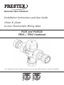
Installation Instructions and User Guide
Domestic Valve Solutions
15mm & 22mm
In-Line Thermostatic Mixing Valve
Installation Instructions and User Guide
15mm & 22mm
In-Line Thermostatic
MixingP405UA
Valve
P405 and
TMV3/TMV2
Combined
P405 and P405UA
TMV3 / TMV2 Combined
It is important that these guidance notes are read and fully understood prior to product installation
t is important that these guidance notes are read and fully understood
prior to product installation
The Pegler Yorkshire Model P405 mixing valve must be installed in accordance with the reg
local water company and the Water Supply (Water Fittings) Regulations 1999.
Approvals
P405 When used as a TMV3 (TYPE3) valve:
IMPORTANT INTRODUCTION NOTES
The valves covered by these instructions have been
tested and certified as being in compliance with BS
7942:2000 and NHS Estates Model Engineering
Specification D 08.
This product is certified under the BuildCert TMV3 scheme and has been independently tes
the
location of the mixing valve and should always be
recognised test laboratory WRc-NSF and is a Water Regulations Advisory Scheme (WRAS)
and listed in the
Water Fittings and Materials Directory.
inproduct
an accessible
location.
Installation
Before installation, the hot and cold water supply
Separate isolation valves must be installed on the hot and cold water inlet supplies. To ens
systems
must
bethermostatic
thoroughly
remove
performance
of the
mixingflushed
valve, the to
isolating
valvesany
should preferably be ful
always be fullythat
open during
operation.
dirt/debris
may have
accumulated. Failure to do
The mixing valve is supplied with filter elements but it is advisable to additionally install
soY-strainers
may adversely
affect
the
performance
of
the
on the hot and cold water supplies. The isolating valves and strainers should be
close as valve.
practicable to the location of the mixing valve and should always be in an accessib
mixing
Before installation, the hot and cold water supply systems must be thoroughly flushed to re
Valves operating outside the requirements of these
standards are not covered by the TMV3 Scheme and
are not guaranteed to operate as Type 3 valves.
alves
The installer should be aware of his duty of care and
responsibility in ensuring that compliance with
regulations is maintained. The valve is not guaranteed
to function correctly to the TMV3 specification
unless it is installed and used in accordance with
these instructions.
Regular servicing is essential to ensure continued safe
operation of this thermostatic mixing valve. The
recommended service interval must be based on the
operating
outside
these cold
conditions
can not
valve response
to the in-service
water failure
test results.
This Pegler Yorkshire Model P405 in-line thermostatic
dirt/debris that may have accumulated. Failure to do so may adversely affect the performa
Conditions
of normal Use
mixing valve.
CONDITIONS OF NORMAL USE
Table 1
Table 1
Operating Range
High Pressure
Low Pressure
Maximum static pressure - bar
10
10
Hot & cold flow pressure - bar
1.0 to 5
0.2 to 1
Hot supply temperature - °C
52 to 65
52 to 65
Cold supply temperature - °C
5 to 20
5 to 20
Minimum hot inlet to mixed outlet temperature differential =10°C
Minimum hot inlet to mixed outlet temperature
differential =10°C
Note: Valves operating outside these conditions can
be guaranteedby
by the
to operate
as Type
be not
guaranteed
theScheme
Scheme
to operate
as Ty
3 valves.
The highest flow rates will be achieved under balanced
pressure conditions, but the pressure at the valve
hest flow
rates
be achieved
balanced
pressure
conditions, but the pressure at the val
mixing
valve,will
available
in 15mm andunder
22mm sizes,
is
inlets must be within a ratio of 5:1 under flow
fittedof
into5:1
applications
ust be intended
within toa beratio
under where
flowthe
conditions and
the
and
ofofpipework
conditionssize
and the
sizelayout
and layout
pipework andand fitting
reliable control of hot water temperature is necessary
fittings
must
take
this
into
account.
ke this tointo
account.
prevent
scalding. In the event of cold water supply
failure, the product will shut off the hot water supply.
FITTING
Water regulations
Before installation, the system operating conditions of
inlet pressures, hot water temperature and hot and
nstallation,
theYorkshire
system
operating
The Pegler
Model
P405 mixingconditions
valve must be of inlet pressures, hot water temperature and hot a
cold water flow rates should be determined and
installed
in
accordance
with
the
regulations
of
the
ter flow rates should be determined and confirmed confirmed
to be within
thethe
expected
conditions
of norm
to be within
expected conditions
of
local water company and the Water Supply (Water
normal use.
Fittings) Regulations 1999.
Valves must operate in either a high pressure setting
Approvals
must operate
in either a high pressure setting or a low
pressure
setting
valves
not
or a low
pressure setting
valves
are not are
capable
of capable o
operation
with,
for instance
hot water
supply in
on with, for instance hot water supply in one pressure
range
and
cold water
supply
inone
the other
This product is certified under the BuildCert TMV3
pressure range and cold water supply in the other
e range.
In these
it istested
necessary
boostrange.
oneInpressure
or
reduce
the
other so
scheme
and has conditions
been independently
by the to eitherpressure
these conditions it is necessary to
recognised
laboratory
WRc-NSF and
is a Water range.
h supplies
are test
within
a common
pressure
either boost one pressure or reduce the other so
Regulations Advisory Scheme (WRAS) approved
product and listed in the Water Fittings and Materials
Directory.
that both supplies are within a common pressure
range.
location of the mixing valve is important to ensure Correct
that itlocation
is accessible
commissioning
and
of the mixingfor
valve
is important to
Installation
ensure that it is accessible for commissioning and
g.
servicing.
Separate isolation valves must be installed on the hot
• The valve body is and cold water inlet supplies. To ensure proper
performance
of the thermostatic
valve,for
the Cold and a clearly
valve body
is clearly
marked mixing
with ‘C’
blue marked with ‘C’ for Cold and a isolating valves should preferably be full bore and
cator and
‘H’ for Hot and a red indicator.
blue indicator and
always be fully open during operation.
‘H’ for Hot and valve must
be valve
correctly
connected
to thebutrespective supplies.
The mixing
is supplied
with filter elements
a red indicator. The it is advisable to additionally install Y-strainers on the
valve must be hot and cold water supplies. The isolating valves and
correctly connected strainers should be installed as close as practicable to
to the respective supplies.
2
use of sealing compounds must be avoided since they may intrude into the water supply and
• The use of sealing compounds must be avoided since they may intrude into the water supply and impair the valve performance.
Exploded view of angled valve assembly
PRESSURE TAKE-OFF POINT PLUG
The Pegler Model Yorkshire P405UA
mixing valve is optionally p
SEAL
the tailpiece arrangement shown above. This allows the connec
be parallel to the mixed water outlet for ease of piping layouts.
HEADWORK
non-return valves, filters, isolation
valves and test points
The Pegler Yorkshire Model P405 thermostatic mixing
valve is supplied with the tail pieces, inlet filter
screen and main body gasket seals separately located
in the packing box.
Each tail piece comprises: a housing with union nut
and an internally fitted, WRAS approved non-return
valve.
SEAL
The assemblies comprise an integral
full bore ball valve and inFILTER MESH
UNION
this arrangement is used, the requirements
for isolation valves
UNION NUT
SEAL
regarded as fulfilled.
Assembly Procedure
ISOLATION
VALVE
HANDLE
Exploded view of angled valve assembly
• Unpack the main valve assembly and check that the bores are free of debris and the end sealing
faces are clean.
• Unpack the two tailpieces and confirm they are complete with union nuts and compression nuts
and olives.
• Locate the sealing gaskets, insert them into the union nuts against the faces of the tailpieces and
screw the union nuts onto the valve until a tight seal has been made.
• Remove the compression nuts and olives from the tailpieces. Locate the inlet filter screens and
insert them into the bore of the tailpieces up to the shoulder.
• Assemble the valve to the pipework and ensure the hot and cold water pipes have full
penetration into the tailpiece.
• Tighten the compression nuts ensuring that the end of the pipe remains in contact with the filter
element.
ISOLATION VALVE
Application
The Pegler Yorkshire Model P405 thermostatic mixing
valve has been independently tested by WRc-NSF
against the requirements of BS 7942:2000 and NHS
D08APPLICATION
and certified as complying with the requirements
of the TMV3 Scheme and is suitable for use in the
The Pegler Yorkshire Model P405 thermostatic mixing valve has been
designations shown in the table below.
the requirements of BS 7942:2000 and NHS D08 and certified as com
Scheme and is suitable for use in the designations shown in the table
Valves approved for designation for use ‘HP’ only:-
If a water
supplyfor
is designation
fed by gravityfor
then
the
supply
Valves
approved
use
‘HP’
only:- If a water s
pressure
should
be verified
to ensure
the the
conditions
of of use are
supply
pressure
should
be verified
to ensure
conditions
use are appropriate for the valve.
Exploded
viewpipe
of tail
pipe assembly
Exploded view
of tail
assembly
Table 2 – Required maximum set outlet
temperatures
commissioning.
Table
2 – Requiredatmaximum
set outlet temperatures at com
Application
Bidet
Designation
HP-B
LP-B
Maximum Set Mixed
Water Temperature
38°C
The Pegler Model Yorkshire P405UA mixing valve is
Shower
HP-S
41°C
optionally
withP405UA
angled assemblies
in lieu
The Pegler
Modelprovided
Yorkshire
mixing valve
is of
optionally provided with angled
LP-S assemblies in lieu of
the
tailpiece
arrangement
shown
above.
This
allows
the tailpiece arrangement shown above. This allows the connections
of the hot
and cold water supplies
Washbasin
HP-W
41°C to
the connections
of the
hot outlet
and cold
to layouts. The angled valve
LP-Wassemblies incorporate
be parallel
to the mixed
water
forwater
easesupplies
of piping
be parallel
tofilters,
the mixed
water outlet
easetest
of piping
non-return
valves,
isolation
valvesforand
points
Bath*
HP-T44
44°C
layouts. The angled valve assemblies incorporate
LP-T44
non-return valves, filters, isolation valves and test
Bath*
HP-T46
46°C
points.
(assisted)
LP-T46
The assemblies
comprise
an integral
fullfull
bore
strainer in an angled housing. When
The assemblies
comprise
an integral
boreball
ballvalve and in-line
*22mmonly
only
*22mm
this arrangement
is used,
the in
requirements
for isolation
valve and in-line
strainer
an angled housing.
When valves and Y-strainers previously mentioned are
regarded
asarrangement
fulfilled. is used, the requirements for
this
The range of available temperature adjustment is 35°C to 48°C BUT
isolation valves and Y-strainers previously mentioned
theThe
terminal
should
never be
set to a temperature
tha
range offitting
available
temperature
adjustment
is
Exploded
of angled
valve assembly
areview
regarded
as fulfilled.
outlet
for the
application
(Table 2).
35°Ctemperature
to 48°C BUT the
mixed
water temperature
at the terminal fitting should never be set to a
Note:
temperature that exceeds the maximum set outlet
46°C is the maximum recommended mixed water temperature from t
temperature for the application (Table 2).
3
takes account of the allowable temperature tolerances inherent in the
losses in metal baths.
46°C is not a safe bathing temperature for adults or children.
Note:
•
•
46°C is the maximum recommended mixed water
temperature from the bath tap. The maximum
temperature takes account of the allowable
temperature tolerances inherent in thermostatic
mixing valves and temperature losses in metal baths.
46°C is not a safe bathing temperature for adults
or children.
Bath*
HP-T44
44°C
The British Burns
Association recommends 37°C to
LP-T44
37.5°C
Bath* as a comfortable
HP-T46 bathing temperature
46°C for
children. In premises
(assisted)
LP-T46 covered by the Care Standards
Act 2000, the maximum mixed water outlet
temperature
*22mm
only is 43°C.
using a close fitting spanner, reduce the mixed outlet temperature by turning clockwise.
increase the mixed water outlet temperature by turning counter clockwise.
When the valve has been installed with the correct
conditions of use it is advised that the valve is
subjected to exercise prior to the commissioning at
the application temperature. With hot and cold water
flowing through the valve, operate the valve from full
cold to full hot at least three times.
With the valve at the full cold position bring the valve
to the correct application temperature by turning the
spanner counter clockwise. If the valve overshoots
thisthe
temperature,
returntemperature
the valve to theatfull cold
The range
of available temperature
mixed water
COMMISSIONING
(TMV 3) adjustment is 35°C to 48°C BUT
condition,
and the
resetmaximum
it to the correct
the terminal fitting should never be set to a temperature that
exceeds
set temperature
+0-2°C. Do not set a valve on a lowered temperature
valve must be
under (Table
normal site
outlet The
temperature
forcommissioned
the application
2).
as this will not provide consistent operation.
system conditions and after establishing supply
Note: conditions with the hot and cold water supplies open,
When
set maximum
to the required
temperature for
the systemrecommended
running to allow
temperatures
and
46°C is leave
the maximum
mixed
water temperature
from
the the
bathvalve
tap.isThe
temperature
the applicationmixing
carry out
5 cold
isolation tests
takes account
ofto
the
allowable
valves
andwater
temperature
pressures
stabilise
and temperature
be checked. tolerances inherent in thermostatic
to further exercise the valve.
losses in metal baths.
commissioning,
thefor
following
46°C isPrior
nottoa commencing
safe bathing
temperature
adults or children.
Commissioning Test sequence
checks should be carried out.
The British Burns Association recommends 37°C to 37.5°C as a comfortable bathing temperature for children.
adjust
thebring
temperature
water
in
• Thecovered
designation
of the
thermostatic
valve
maximum
In premises
by the
Care
Standards mixing
Act
2000,
the
mixed
water
outlet
is
43°C.
With
the
valve
at the fullAfter
cold
position
thetemperature
valveoftothe
themixed
correct
application
tempera
accordance
withovershoots
the valve application
(see Table
matches the application.
spanner counter clockwise.
If the valve
this temperature,
return the valve to
2)
and
the
carry
out
the
following
sequence:
COMMISSIONING
(TMV 3)and temperaturescondition,
• The supply pressures
are withinand
reset it to the correct temperature +0-2°C. Do not set a valve on a lower
1.Record
the temperature of the hot and cold water this will not provide consistent
operation.
the operating range of the valve.
supplies.
The valve
must be valves
commissioned
under
site system conditions
and after establishing
• Isolating
and strainers
are normal
provided.
When
set to2.Record
the system
required
temperature
forthe
the
application
therunning
temperature
of
mixed
water carry
at theout
5 cold wa
supply conditions
with
the hot and
water
supplies
open,is leave
the
to allow
temperatures
• The supply
temperatures
arecold
within
the
rangethe
valve
to further
largest draw-off flow rate.
and pressures
to stabilise
checked.
permitted
for the and
valvebeand
by guidance
exercise the valve.
3.Record the temperature of the mixed water flow information on the prevention of legionella etc.
Commissioning
Testbe
sequence
carried
at a smaller
Prior to commencing commissioning, the following
checks should
out. draw-off flow rate, which shall be measured.
If all these conditions are met, proceed to set the
After adjust
temperature
of thethe
mixed
accordance
with thevalve
valve application
4.Isolate
cold water
water in
supply
to the mixing
• temperature
The designation
of the below.
thermostatic
mixing
valvethe
matches
the
application.
as described
The Pegler
Yorkshire
2) and the carry out the following
sequence:
and range
monitor
• model
The supply
pressures and
temperatures
are within the operating
ofthe
themixed
valve.water temperature recording P405 thermostatic
mixing
valve is supplied
1. Record the temperature of the hot and cold water supplies.
the maximum temperature achieved and the final • factory
Isolating
set valves
at 43°Cand
but strainers
the valve are
mayprovided.
be simply
2. Record the temperature of the mixed water at the largest draw-off flow
stabilised
temperature.
• adjusted
The supply
forthe
the
valve and
bythe
guidance
information
aftertemperatures
installation. are within the range permitted
3. Record
temperature
of
mixed water
flow at a smaller draw-off fl
5.Record the equipment, thermometer etc. used for on the prevention of legionella etc
which shall be measured.
thethe
measurements.
If all these
conditions
met, proceed
to set
the temperature
as described
below.
The mixed
waterare
temperature
at the
terminal
fitting
4. Isolate
cold
water
supply to the mixing valve and monitor the mixed
Note:factory
The final
stabilised
should
not and the fina
The Pegler
model
thermostatic
mixing valve temperature
is supplied
setthe
at maximum
43°C temperature
but temperature
the valve
may
mustYorkshire
never exceed
theP405
maximum
temperature
recording
achieved
exceed the values in Table 3.
be simply
adjusted
after
installation.
setting
for the
particular
application (See Table 2). temperature.
5. Record
the equipment,
etc. used for the measurements.
The mixed
temperature
at the
terminal
fitting
must never
exceed thermometer
the maximum
Note, water
It is not
possible to install
one
thermostatic
Note: The final
stabilised
temperature
should
not
exceed the
values
in Table3
temperature
setting
for the
particular
application
(See
Table
2). 3
Note,
It
is to
not
possible
to
install
mixing valve
to supply
two
differing applications
Table
– Guide
maximum
stabilised
one thermostatic
mixing valve
tohigher
supply
two differing
applications
unlessrecorded
the temperature
unless the temperature
of the
setting
is
temperatures
during of the
higherlimited
settingtoisthat
limited
thatapplication.
of the lower application. commissioning
of thetolower
Table 3 – Guide to maximum stabilised temperatures recorded during comm
• •Remove
capon
ontop
topofofthe
the valve with the supplied Allen key or other suitable tool.
Removethe
the plastic
plastic protective
protective cap
Application
Mixed water temperature °C
valve with the supplied Allen key or other suitable Bidet
40
tool.
o using a close fitting spanner,
Shower
43
reduce theWashbasin
mixed outlet
43
temperature
turning
Bath by
(44°C
fill)
46
clockwise.
Bath (46°C fill)
48
o increase the mixed water
outlet temperature by turning counter
clockwise.
4
After correct commissioning secure the protective cap u
supplied screw. The Pegler Yorkshire model P405 is sup
two protective caps. One blue TMV 3 cap and one whit
Ensure that the blue colour TMV 3 cap is fitted as this w
Bath (46°C fill)
48
With an acceptable mixed water temperature complete
the Commissioning test sequence detailed above. If
the final mixed water temperature is greater than the
values in
Table 3 and/or the maximum
After correct
commissioning
secure temperature
the protective cap
theThe
corresponding
from the previous
supplied exceeds
screw.
Pegler value
Yorkshire
model P405 is s
test results by more than about 2°C the need for
two protective
caps.
One blue
TMV
3 cap
service work
is indicated
(see TMV
servicing
and and one wh
cleaning
Ensure that
theinstructions).
blue colour TMV 3 cap is fitted as thi
the valve has been commissioned to the TMV 3 stand
In-service tests should be carried out with a frequency
which identifies a need for service work before an
unsafe water temperature can result.
Frequency of in-service testing
6 to 8 weeks after commissioning carry out the test
sequence detailed above.
AfterIn
correct
commissioning
secure(TMV
the protective
Service
Testing
3) cap
12 to 15 weeks after commissioning carry out the test
using the supplied screw. The Pegler Yorkshire model
sequence detailed above.
P405 is supplied with two protective caps. One blue
ofTMV
in-service
testing
monitor
andobtained,
recordthethe
performance o
Depending
on the results
following
TMVThe
3 cap purpose
and one white
2 cap. Ensure
that theis to regularly
of actions mustcan
be followed:
bluethermostatic
colour TMV 3 cap is
fitted as valve.
this will indicate
the
mixing
Deterioration
incourse
performance
indicate the need for serv
valve has been commissioned to the TMV 3 standard.
valve and/or water supplies.
• If no significant changes (e.g.<1 °C) in mixed
water temperature are recorded between In Service Testing (TMV 3)
using
commissioning
and testing
at 6 to 8 weeks,equipment
or Carry out the test sequence detailed below
the same
or equivalent
as
between commissioning and testing at 12 to
The purpose of in-service testing is to regularly
commissioning the valve.
15 weeks, the next in-service test can be deferred monitor and record the performance of the
to 24 to 28 weeks after commissioning.
thermostatic mixing valve. Deterioration in
• If small
changes
(e.g.1 to the
2 °C)application.
in mixed water performance
can indicate
the need for service
• Check
the designation
of work
the on
thermostatic
valve
matches
temperature are recorded in only one of
the valve and/or water supplies.
• Check that the supply pressures and temperatures
are within
the operating
range
these periods, necessitating
adjustment
of the mixed
water
temperature,
then
the
next
inservice
Carry out the test sequence detailed below using
test can be deferred to 24 to 28 weeks after the same or equivalent equipment as used for
commissioning.
commissioning the valve.
• If small changes (e.g.1 to 2 °C) in mixed water temperature are recorded in both of these
• Check the designation of the thermostatic valve periods, necessitating adjustment of the mixed matches the application.
water temperature, then the next in-service
• Check that the supply pressures and temperatures test should be carried out at 18 to 21 weeks after are within the operating range of the valve.
commissioning.
• Check that the supply temperatures are within the • If significant changes (e.g. >2 °C) in mixed water range permitted for the valve and by guidance
temperature are recorded in both of these
information on the prevention of legionella etc
periods, necessitating service work, then the next • Check there have been no significant changes in in-service test should be carried out at 18
inlet supply temperatures and pressures since
to 21 weeks after commissioning.
commissioning or the previous in service test.
The general principle to be observed after the first If significant changes have occurred it is
2 or 3 in-service test is that the intervals of future
recommended to re-commission the valve.
tests should be set to those which previous tests have shown can be achieved with no more than a
If the mixed water temperature has changed
small change in mixed water temperature.
significantly from the previous test results (e.g.>1°C),
It is recommended that In-Service Tests are carried record the change and before re-adjusting the mixed
out once every 6 months as a minimum.
water temperature carry out the following checks;
Note:
• All in-line or integral strainers are clean
• Any in-line or integral non-return valves or other anti-backsiphonage devices are in good working order.
• Any isolation valves are fully open.
5
If there is a residual flow during the commissioning or in
service test during the cold water supply isolation test
then this is acceptable providing the temperature of the
water seeping from the valve is no more than 2°C above
the designated maximum mixed water outlet temperature
setting of the valve as defined in Table 2.
The mixing valve is supplied with filter elements but
it is advisable to additionally install Y-strainers on the
hot and cold water supplies. The isolating valves and
strainers should be installed as close as practicable to
the location of the mixing valve and should always be
in an accessible location.
Temperature readings should be taken at the normal flow
rate after allowing the system to stabilise. The sensing
part of the thermometer probe must be fully submerged
in the water that is to be tested.
Any TMV that has been adjusted or serviced must be
re-commissioned and re-tested in accordance with the
manufacturer’s instructions.
Before installation, the hot and cold water supply
systems must be thoroughly flushed to remove any
dirt/debris that may have accumulated. Failure to do
so may adversely affect the performance of the
mixing valve.
P405 When used as a TMV2 (TYPE 2) Valve
IMPORTANT INTRODUCTION NOTES
The valves covered by these instructions have been
tested and certified as being in compliance with BS
EN 1111:1999 and BS EN 1287:1999.
Valves operating outside the requirements of these
standards are not covered by the TMV2 Scheme and
are not guaranteed to operate as Type 2 valves.
CONDITIONS OF NORMAL USE
CONDITIONS OF NORMAL USE
Table 4
Table 4
Operating Range
Maximum static pressure - bar
Hot & cold flow pressure - bar
Hot supply temperature - °C
Cold supply temperature - °C
Mixed water temperature - °C
BS EN 1111
High Pressure
10
1.0 to 5
55 to 65
≤ 25
Maximum 46
BS EN 1287
Low Pressure
10
0.1 to 1
55 to 65
≤ 25
Maximum 46
The installer should be aware of his duty of care and
responsibility in ensuring that compliance with
regulations is maintained. The valve is not guaranteed Minimum hot inlet to mixed outlet temperature differential =10°C
Minimum hot inlet to mixed outlet temperature
to function correctly to the TMV2 specification
Note: Valves operating outside these conditions can not be guaranteed by the Scheme to operate as T
unless it is installed and used in accordance with
2 valves. differential =10°C
these instructions. Regular servicing is essential to
The highest flow rates will be achieved under balanced pressure conditions, but the pressure at the va
Note:
Valves
outside
these
conditions
can
ensure continued safe operation of this thermostatic
inlets must
be within
a ratio operating
of 5:1 under flow
conditions
and the
size and layout
of pipework and fittin
must take this into account.
not be guaranteed by the Scheme to operate as Type
mixing valve. The recommended service interval is no
2 valves.
FITTING
greater than 12 months.
This Pegler Yorkshire Model P405 in-line thermostatic
mixing valve, available in 15mm and 22mm sizes, is
intended to be fitted into applications where the
reliable control of hot water temperature is necessary
to prevent scalding. In the event of cold water supply
failure, the product will shut off the hot water supply.
Water regulations
The Pegler Yorkshire Model P405 mixing valve must
be installed in accordance with the regulations of
the local water company and the Water Supply
(Water Fittings) Regulations 1999.
Approvals
This product is certified under the BuildCert TMV2
scheme and has been independently tested by an
approved testing laboratory WRc-NSF and is a Water
Regulations Advisory Scheme (WRAS) approved
product and listed in the Water Fittings and Materials
Directory.
Before installation, the system operating conditions of inlet pressures, hot and cold inlet temperature a
hot and cold
flow rates
should
be determined
confirmedunder
to be within
the expected condition
Thewater
highest
flow
rates
will be and
achieved
balanced
of normal use shown in Table 4.
pressure conditions, but the pressure at the valve
Valves must
operate
in either
high pressure
setting
a lowunder
pressureflow
setting. These valves are not
inlets
must
be awithin
a ratio
ofor5:1
capable of operation with, for instance hot water supply in one pressure range and cold water supply
theconditions
size and
pipework
and
the other conditions
pressure range.and
In these
it is layout
necessaryof
to either
boost one
pressure or reduce th
other so that
both supplies
within
a common
pressure range.
fittings
mustare
take
this
into account.
If your water supply cannot meet these conditions then the valve cannot be guaranteed to operate as
Type 2 valve.
FITTING
Operating pressures above 5.0 Bar will require the installation of a pressure reducing valve.
Correct location of the mixing valve is important to ensure that it is accessible for commissioning and
servicing.
Before installation, the system operating conditions of
inlet pressures, hot and cold inlet temperature and
The valve body is clearly marked with ‘C’ for Cold and a blue
hotand
and
flow
rates should be determined
indicator,
‘H’ cold
for Hotwater
with a red
indicator.
The valve must be correctly connected to the respective supplies.
and confirmed to be within the expected conditions
of normal use shown in Table 4.
•
•
The use of sealing compounds must be avoided since they may intrude into the water supply an
impairValves
the valvemust
performance.
operate in either a high pressure setting
•
The valve must be so installed that it is readily accessible for commissioning and maintenance wh
beingcapable
installed in of
accordance
with TMV2.
operation
with, for instance hot water
•
The valve must be installed with isolation valves on both the hot and cold water systems as close
possible
the valve;
so as to allow
the valve
be commissioned
and it
tested
theto other
pressure
range.
In to
these
conditions
is correctly.
or a low pressure setting. These valves are not
supply in one pressure range and cold water supply in
necessary
either
pressure
orwater
reduce
thetherefore in-line
The valve
is suppliedto
with
integralboost
strainersone
on the
hot and cold
supplies
strainers
should
be required.
other
sonotthat
both supplies are within a common
•
pressure range.
If your water supply cannot meet these conditions
then the valve cannot be guaranteed to operate as a
Type 2 valve.
Installation
Separate isolation valves must be installed on the hot
and cold water inlet supplies. To ensure proper
performance of the thermostatic mixing valve, the
isolating valves should preferably be full bore and
always be fully open during operation.
Operating pressures above 5.0 Bar will require the
installation of a pressure reducing valve. Correct
location of the mixing valve is important to ensure
that it is accessible for commissioning and servicing.
6
Exploded view of tailpiece assembly
• The valve body is Exploded view of tail pipe assembly
ld and a clearly
blue marked with ‘C’ for Cold and a blue indicator and
‘H’ for Hot and spective supplies.
a red indicator. The valve must be correctly connected to the respective supplies.
The Pegler Yorkshire Model P405UA mixing valve is
since they may intrude into the water supply
and
The
Pegler Model Yorkshire P405UA mixing valve is optionally p
optionally provided with angled assemblies in lieu of
the tailpiece
arrangement shown above. This allows the connec
the tailpiece arrangement shown above. This allows
be parallel
to
the mixed
water
forwater
easesupplies
of piping
the connections
of the
hot outlet
and cold
to layouts.
non-return
valves,
filters,
isolation
valves
and
test
points
be
parallel
to
the
mixed
water
outlet
for
ease
of
g valve is supplied with the tail pieces, inlet filter
piping layouts.
ed in the
packing
box.
• The
valve must
be so installed that it is readily The assemblies comprise an integral full bore ball
accessible forfitted,
commissioning
andapproved
maintenance non-return
valve and in-line strainer in an angled housing. When
and an internally
WRAS
when being installed in accordance with TMV2.
The assemblies
comprise
an integral
full borefor
ball valve and inthis arrangement
is used,
the requirements
isolation valves
and strainers
previously mentioned
are valves
this arrangement
is used,
the requirements
for isolation
• The valve must be installed with isolation valves on regarded
regarded
as fulfilled.
as fulfilled.
both the hot and cold water systems as close as
possible to the valve; so as to allow the valve to be Exploded
ofvalve
angled
valve assembly
Exploded
view of view
angled
assembly
commissioned and tested correctly.
• The use of sealing compounds must be avoided since they may intrude into the water supply and
impair the valve performance.
PRESSURE TAKE-OFF POINT PLUG
that the bores are free of debris and the end sealing
are
• The valve is supplied with integral strainers on the hot and cold water supplies therefore in-line
complete
nuts and compression
strainerswith
shouldunion
not be required.
SEAL
nuts
HEADWORK
• Thenuts
valve is
fitted with
integral
“listed”
non-return
the union
against
the
faces
of the
tailpieces
and
valve cartridges which command the water supply,
tight seal
has been
made. valve is protected therefore
the thermostatic
against cross-flow
due to
unbalanced
line pressures
and
om the tailpieces.
Locate
the
inlet filter
screens
as required by the Water Supply (Water Fittings) p to the shoulder.
Regulations 1999.
sure the hot and cold water pipes have full
ISOLATION
SEAL
FILTER MESH
UNION NUT
UNION
SEAL
VALVE
HANDLE
Assembly Procedure
the end of the pipe remains in contact with the filter
• Unpack the main valve assembly and check that the bores are free of debris and the end sealing faces APPLICATION
ISOLATION VALVE
are clean.
• Unpack the two tailpieces and confirm they areThe
Pegler Yorkshire Model P405 thermostatic mixing valve has been
complete with union nuts and compression nuts
the requirements of BS 7942:2000 and NHS D08 and certified as com
and olives.
Scheme and is suitable for use in the designations shown in the table
• Locate the sealing gaskets, insert them into the APPLICATION
union nuts against the faces of the tailpieces and
Valves approved for designation for use ‘HP’ only:- If a water s
screw the union nuts onto the valve until a tight Theshould
Pegler Yorkshire
Model
thermostatic
mixing of use are
supply pressure
be verified
to P405
ensure
the conditions
seal has been made.
valve has been independently tested by WRc-NSF
• Remove the compression nuts and olives from the against the requirements of BS EN 1287 (Low Pressure tailpieces. Locate the inlet filter screens and
LP) and BS EN 1111 (High Pressure-HP) and
insert them into the bore of the tailpieces up to the certified as complying with the requirements of the
shoulder.
TMV2 Scheme and is suitable for use in the
maximum set outlet temperatures at com
• Assemble the valve to the pipework and ensureTable
the 2 – Required
designations shown in the table (next page).
hot and cold water pipes have full penetration into Application
Designation
Maximum
Mixed
the tailpiece.
Valves approved
for designation
for Set
use ‘HP’
only:Water
Temperature
• Tighten the compression nuts ensuring that the end If a water supply is fed by gravity then the supply
of the pipe remains in contact with the filter
Bidet pressureHP-B
should be verified to ensure38°C
the conditions
element.
of use are
appropriate for the valve.
LP-B
Shower
Washbasin
7
HP-S
LP-S
HP-W
LP-W
41°C
41°C
APPLICATION
The Pegler Yorkshire Model P405 thermostatic mixing valve has been independently tested by WRc-NSF
against the requirements of BS EN 1287 (Low Pressure-LP) and BS EN 1111 (High Pressure-HP) and
certified as complying with the requirements of the TMV2 Scheme and is suitable for use in the
designations shown in the table below.
•
Remove the plastic protective cap on top of the valve with
Table 5 – Recommended set mixed water
outlet temperatures
o using
reduc
temp
clock
Valves approved for designation for use ‘HP’ only:- If a water supply is fed by gravity then the
supply pressure should be verified to ensure the conditions of use are appropriate for the valve.
Table 5 – Recommended set mixed water outlet temperatures
Pressure
Application
Shower
Wash basin
Bidet
Bath (Tub)
15mm
HP
HP
HP
HP
22mm
HP and LP
HP and LP
HP and LP
HP
Maximum set mixed
water temperature
41°C
41°C
38°C
44°C
o increa
outle
clock
The above temperatures are recommended by the Thermostatic Mixing Valve (manufacturers) Association
as relevant settings for the varying applications shown. This is the maximum commissioning temperature
but valves may exceed this by 2°C in use.
The range of available temperature adjustment is 35°C to 48°C but
46°C is the maximum recommended mixed water temperature from a bath tap. The maximum temperature
takes account of the allowable temperature tolerances inherent in thermostatic mixing valves and temperature
losses in metal baths.
46°C is not a safe bathing temperature for adults or children.
The above temperatures are recommended by the
Thermostatic Mixing Valve (manufacturers) Association
as relevant settings for the varying applications
• using
a close
fitting
When
the valve
has
beenspanner,
installedreduce
with the
the correct
conditions o
shown. This is the maximum commissioning
mixed prior
outlettotemperature
by turningatclockwise.
the commissioning
the application tempe
temperature
but valves
exceed
this by
2°C
in use.
The British
Burns Association recommends
37°C may
to 37.5°C
as a comfortable
bathing
temperature
for children. to exercise
In premises covered by the Care Standards Act 2000, the maximum mixed water outlet temperature is 43°C.
• increase
the mixed
water
outlet
by to full hot at
through
the valve,
operate
the
valvetemperature
from full cold
COMMISSIONING (TMV 2)
turning counter clockwise.
The range of available temperature adjustment is
The valve35°C
must be to
commissioned
under46°C
normal site
conditions and after
establishing
48°C but
is system
the maximum
recommended
supply conditions with the hot and cold water supplies open, leave the system running to allow temperatures
When the valve has been installed with the correct
and pressures
to stabilise
and be
checked.
mixed
water
temperature
from a bath tap. The
conditions of use it is advised that the valve is
maximum
temperature
takes
of the
Prior to commencing
commissioning,
the following
checksaccount
should be carried
out. allowable
subjected to exercise prior to the commissioning at
temperature
inherent
inthethermostatic
• The
designation of thetolerances
thermostatic mixing
valve matches
application.
• The supply pressures and temperatures are within the operating range of the valve.
the application temperature. With hot and cold water
mixing
valves
and
temperature
losses
in
metal
baths.
• Isolating valves and strainers are provided.
flowing through the valve, operate the valve from full
46°C is not a safe bathing temperature for adults
If all these conditions are met, proceed to set the temperature as described below.
cold to full hot at least three times.
or children.
The Pegler Yorkshire P405 thermostatic mixing valve is supplied factory set at 43°C but the valve may be
simply adjusted after installation.
The set mixed water temperature at the terminal fitting must never exceed 46°C
•
With the valve at the full cold position bring the valve
to the correct application temperature by turning the
spanner counter clockwise. If the valve overshoots this
temperature, return the valve to the full cold
condition, and reset it to the correct temperature
+0-2°C. Do not set a valve on a lowered temperature
as this will not provide consistent operation.
The British Burns Association recommends 37°C to
37.5°C as a comfortable bathing temperature for
children. In premises covered by the Care Standards
Act 2000, the maximum mixed water outlet
temperature is 43°C.
Remove the plastic protective cap on top of the valve with the supplied Allen key or other suitable
tool.
COMMISSIONING (TMV 2)
The valve must be commissioned under normal site
system conditions and after establishing supply
conditions with the hot and cold water supplies open,
leave the system running to allow temperatures and
pressures to stabilise and be checked.
When the valve is set to the required temperature for
the application carry out 5 cold water isolation tests
to further exercise the valve.
• Set the mixed water temperature to the required value. It is advisable to use a calibrated digital
thermometer for checking the inlet and outlet temperatures.
Prior to commencing commissioning, the following
checks should be carried out.
•
•
•
The designation of the thermostatic mixing valve matches the application.
The supply pressures and temperatures are within the operating range of the valve.
Isolating valves and strainers are provided.
If all these conditions are met, proceed to set the temperature as described below.
• Measure and record the temperature of the hot and cold water supplies at the inlets to the valve.
• Measure and record the temperature of the water discharging from the valve at the greatest draw-off
flow rate.
• In the absence of other temperatures being specified those detailed in Table 5 are the desired settings.
The Pegler Yorkshire P405 thermostatic mixing valve is
supplied factory set at 43°C but the valve may be
simply adjusted after installation.
The set mixed water temperature at the terminal
fitting must never exceed 46°C
Once the required mixed outlet temperature has been
achieved, isolate the cold water supply and monitor
and record the mixed water temperature including the
maximum and final temperatures achieved. The mixed
water temperature should never exceed 46°C.
• Remove the plastic protective cap on top of the valve with the supplied Allen key or other suitable
tool.
8
Once the required mixed outlet temperature has been achieved, isolate the cold
monitor and record the mixed water temperature including the maximum and
achieved.
Thesecure
mixed
water temperature
should
exceed
46°C.the
After correct
commissioning
the protective
Isolate
the coldnever
water supply
and RECORD
cap using the supplied screw. The Pegler Yorkshire
Model P405 is supplied with two protective caps.
One blue TMV 3 cap and one white TMV 2 cap. Ensure
that the white colour TMV 2 cap is fitted as this will
indicate the valve has been commissioned to the TMV
2 standard.
maximum temperature achieved. After 5 seconds, if
water is still flowing RECORD the temperature of the
flow. Restore the cold water supply and RECORD the
stabilised mixed water outlet temperature.
•
If there is no significant change to the stabilised set outlet temperature (±2°C or less deviation from the original setting) and the fail safe shut-off is functioning, then the valve is working correctly and no further service work is required.
After correct
secure
theexceeds
protective
ca
• If thecommissioning
maximum mixed water
temperature
supplied screw.
The
Yorkshire
Model
P405 is
the previous
testPegler
results by
more than 2°C
then the
need
for service
the valve
is indicated.
protective
caps.
One work
blueonTMV
3 cap
and one white
that the•white
colour
TMV
2
cap
is
fitted
The equipment used in these In-Service Tests as
this will
should
be RECORDED to
andthe
should
preferably
be the has been
commissioned
TMV
2 standard.
same as that used at installation.
Note:
If there is a residual flow during the commissioning
Record all the equipment used during commissioning.
the annual verification (cold water supply isolation
Record all the equipment used during or
commissioning.
test) then this is acceptable providing the temperature
of the water seeping from the valve is no more than
2°C above the designated maximum mixed water
outlet temperature setting of the valve (See Table 5).
In Service testing (TMV 2)
The Pegler Yorkshire Model P405 thermostatic mixing
valve will provide satisfactory service and a high level
of protection, provided it is maintained and subjected
to In-Service Testing.
Temperature readings should be taken at the normal
flow rate after allowing the system to stabilise. The
sensing part of the thermometer probe must be fully
submerged in the water that is to be tested. Any TMV
that has been adjusted or serviced must be
re-commissioned and re-tested in accordance with the
manufacturer’s instructions.
Approximately 6-8 weeks after commissioning, the
following tests should be undertaken.
• Check the temperature of the hot and cold water supplies - RECORD
• Check the temperature of the mixed water
temperature at the greatest draw off flow rate – RECORD
• Check there have been no significant changes in inlet supply temperatures and pressures since
commissioning or the previous in service test.
If significant changes have occurred it is
recommended to re-commission the valve.
In the absence of any other instruction or guidance,
it is recommended that In-Service Tests are carried
out once every 12 months as a minimum. If the
temperature is outside of the expected range it will be
necessary to remove and clean the valve in accordance
with the following instructions.
TMV Cleaning and Servicing Instructions
(TMV 2 & TMV 3)
If the mixed water temperature has significantly
changed from that measured at installation
(e.g. > 1°C), RECORD the change and before making
any adjustments to the valve confirm that:-
Most domestic water supplies contain calcium which
will separate out when the water is heated in a
system. The degree and speed of scaling may vary
depending on factors such as water flow rates,
system design, the hardness of the water and the
temperature to which the water is heated.
Deposits of scale may over time form in the valve,
particularly at the hot inlet. The formation of the
scale may adversely affect the performance of the
valve which will be detected during the in-service
testing. If this occurs it will be necessary to remove
the valve for de-scaling and servicing.
• Strainer elements in the hot and cold water supplies
are clean and undamaged.
• Non-return valves are clean and operating correctly.
• Isolation valves are operating correctly and are set in the fully open position.
If the mixed water temperature is acceptable, the
following additional observations should be made:-
9
30.0°
• Isolate the hot and cold supply.
• Remove the valve to a clean working area.
• Remove the protective cap.
• Unscrew the headwork of the valve.
• Carefully remove the element and valve assembly and put to one side.
• Remove the main spring and flow guide and carefully put to one side.
• Inspect the components for contamination or damage.
• Clean or replace as necessary
• Remove the two o rings
• Clean the valve body and headwork using a propriety de-scaler
• Thoroughly rinse the body and headwork in clean water.
• Carefully fit new o rings from the service kit taking care to ensure they are not damaged and are correctly located.
• Lubricate the o rings with the lubricant provided.
• Re-fit the flow guide and spring lubricating the
flow guide around the greatest diameter with the lubricant provided
• Lubricate the shuttle valve with the lubricant provided
• Re-fit the shuttle valve and element assembly.
• Re-fit the headwork ensuring correct tightening
• Re-fit the valve assembly
• If after cleaning the valve, and replacing the o ring seals, the valve does not function correctly, it may be necessary to replace the thermal element.
2
1
3
7
A-1
4
A-2
6
A-1
A-2
B
C
D
E
F
G
Exploded view of TMV assembly
Spare part order code
854550
854551
854447
854454
854449 (15mm), 854450 (22mm)
854451 (15mm), 854452 (22mm)
854456 (15mm), 854457 (22mm)
854455 (15mm), 817012 (22mm)
Description
Blue TMV 3 Protective cap complete with screw
White TMV 2 Protective cap complete with screw
Hexagon key
Service kit
Tailpiece Strainer kit
Angle valve strainer kit
Sealing washer
Wafer Strainer
For genuine spares and technical assistance contact:Pegler Yorkshire
St Catherine’s Avenue
Doncaster
South Yorkshire
DN4 8DF
PRESSURE TAKE-OFF POINT PLUG
SEAL
Tel:
Fax:
HEADWORK
SEAL
FILTER MESH
UNION NUT
4
5
UNION
SEAL
ISOLATION
VALVE
HANDLE
ISOLATION VALVE
Spares
In order to ensure that the Model P405 thermostatic
mixing valve continues to provide satisfactory service,
only GENUINE Pegler Yorkshire spare parts must be
used.
10
01302 560560
01302 560206
Our brands:
UK Sales
Free Phone: 0800 156 0010
Free Fax: 0808 156 1011
Email:[email protected]
Export
Tel:
+44 (0) 1302 855 656
Fax:
+44 (0) 1302 730 513
Email:[email protected]
Technical Help
Free Phone: 0800 156 0050
Free Fax: 0808 156 1012
Email:[email protected]
Brochure Hotline
Free Phone: 0800 156 0020
Free Fax: 0808 156 1011
Email:[email protected]
www.pegleryorkshire.co.uk
Pegler Yorkshire Group Limited
St. Catherine’s Avenue, Doncaster,
South Yorkshire, DN4 8DF, England.
Tel: 0844 243 4400 Fax: 0844 243 9870
Also available from
Pegler Yorkshire:
LUXURY TAP SOLUTIONS
Registered in England Company No. 00401507
Registered Office: Haigh Park Road, Stourton, Leeds,
West Yorkshire, LS10 1RT, England.
All brand names and logo styles are registered trademarks.
Maintaining a policy of continual product development,
Pegler Yorkshire reserves the right to change specifications,
design and materials of products listed in this leaflet without
prior notice.
code ref: 02499185