1
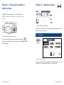
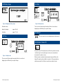
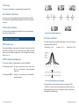
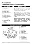
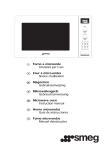
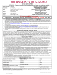
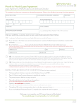
RD533
Radiodetection’s advanced water
leak correlator
Operation Manual l Issue 2 l June 2009
90/RD533-OPMAN-ENG/02
Preface
Before you begin
Thank you for your interest in Radiodetection’s RD533 water leak correlator.
Please read this user manual before attempting to use the RD533 system.
Radiodetection products, including this manual, are under continuous
development. The information contained within is accurate at time of publication;
however the RD533, this manual and all its contents are subject to change.
Radiodetection Limited reserves the right to modify the product without notice
and some product changes may have taken place after this user manual was
published.
Contact your local Radiodetection dealer or visit www.radiodetection.com for
the latest information about the RD533 product family, including this manual.
Important notices
General
This instrument, or family of instruments, will not be permanently damaged by
reasonable electrostatic discharge and has been tested in accordance with
IEC 801-2. However, in extreme cases temporary malfunction may occur.
If this happens, switch off, wait and switch on again. If the instrument still
malfunctions, disconnect the batteries for a few seconds.
Safety
This equipment should be used by fully qualified and trained personnel only.
Reduce audio level before using headphones to avoid damaging your hearing.
WARNING! This equipment is NOT approved for use in
areas where hazardous gases may be present.
ii RD533 Operation Manual
RD533 Operation Manual iii
Training
Radiodetection provides training services for most Radiodetection products.
Our qualified instructors will train equipment operators or other personnel at
your preferred location or at Radiodetection headquarters.
For more information go to www.radiodetection.com or contact your local
Radiodetection representative.
Trademarks
RD533 is a trademark of Radiodetection Ltd.
Copyright statement
Copyright 2009 Radiodetection Ltd – SPX Corporation. All rights reserved.
Radiodetection is a subsidiary of SPX Corporation.
SPX and Radiodetection are trademarks of Radiodetection Ltd. and SPX
Corporation. Due to a policy of continued development, we reserve the right to
alter or amend any published specification without notice.
This document is protected by copyright and may not be copied, reproduced,
transmitted, modified or used, in whole or in part, without the prior written
consent of Radiodetection Ltd.
iv RD533 Operation Manual
Table of contents
Preface
iii
Before you begin
Important notices
General
Safety
Training
Trademarks
Copyright statement
iii
iii
iii
iii
iv
iv
iv
Section 1 – Introduction
1
1.1
1
Overview
Section 2 – Measurement procedures
2
2.1 Setting pipe parameters
2.2 Input of Measurement Parameters
2.3 Measurement Procedure
2.3.1 General issues
2.3.2 Measuring with Automatic Mode
2.3.3 Measuring in Manual Mode
2
3
4
4
4
4
Section 3 – Managing data
5
3.1 Save, load or delete data
3.1.1 General issues
3.2.1 Print Data
5
5
5
Section 4 – Setting the number of radio sections
6
Section 5 – General settings
7
5.1
5.2
5.3
5.4
5.5
5.6
7
8
8
9
9
9
Language
Battery charge
Time
Date
Service
Number of means (N)
RD533 Operation Manual Section 6 – Using a geophone
6.1 Settings
6.1.1 Frequency / Mode of Operation
6.1.2 Volume
6.1.3 Indication of Noise Level
6.1.4 Automatic modulation
6.2 Measurement procedure
6.2.1 General issues
6.2.2 Pre-locating the leakage spot
6.2.3 Precise calibration
Section 7 – Charging the central unit
7.1
7.2
7.3
11
11
12
12
12
12
12
12
13
14
14
14
Section 8 – Appendix
15
Technical specifications
Radio Licence Requirements
1.1 Overview
The RD533 correlator is a multi-function system that is designed to detect leaks
and trace pipeline topography of water supply networks. When used with a
transmitter, the RD533 can trace a pipeline’s route underground.
F.A.S.T.GmbH * Bössingerstr. 36 * D-74243 Langenbrettach
The*system
features a* highly
ground microphone
that
can pinpoint
Tel.: 07946/921000
Fax: 07946/7153
E-mail:sensitive
[email protected]
* Internet:
www.FASTGMBH.de
minute leaks. The automatic frequency search function coupled with automatic
and manual digital filtering allows the operator to locate leaks rapidly with
minimal error.
14
General issues
Memory Effect
Power Supply
8.1
8.2
Section 1 – Introduction
10
15
17
Operating Instructions for the LOKAL 300 Correlator
The RD533 Leak Noise Correlator is based on at least two outstations which
are deployed on suitable fittings surrounding an area of interest.
General issues:The outstations have an extremely sensitive accelerometer which detects and
quantifies leak noise and sends it wirelessly to the Central Unit.
When the LOKAL 300 correlator was designed and developed, it was made sure that the
Measurements
are saved
to theany
central
unit, allowing
the operator
to compare
device can be operated
even without
reading
operating
instructions
due to the
application
readings
over time. With simple
one-button
and additionally
a display thatexplained
of unambiguous
and easy-to-understand
symbols.
These operation
symbols are
automatically
adjusts
brightness,
RD533can
leak
noise correlator
is theafter
idealbrief
in these Operating
Instructions
so that
unskilledthe
workers
operate
the correlator
detection RD533 for a wide variety of industry applications.
studies of theseleak
Instructions.
1: Correlation
Manager
IllustrationFigure
1: Correlation
Manager
By pressing the arrow keys or turning the adjustment control, the requested
By pressing thewindows
arrow keys
or display
by turning
theactivated
adjusting
knob,
the requested
windows
on the
will be
and
displayed
inadvertently.
The on the
display will beselected
activatedsubmenu
and displayed
invertedly.
The
selected
submenu
will
then
be opened
will then be opened by pressing E.
by pressing ”E“ = Enter.
vi RD533 Operation Manual
1.
Measurement Procedures
RD533 Operation Manual nager
deactivated
on the display:
by pressing ”E“ = Enter.
ning the adjusting knob, the requested windows on the
1. The selected
Measurement
Procedures
ed invertedly.
submenu
will then be opened
Section 2 – Measurement procedures
1.1
1.2
1.2
Input
ofofMeasurement
Parameters
2.2
Input
of Measurement
Input
Measurement
Parameters
activated
Parameters
deactivated
The
parameters
`High-Pass
Filter´
`Low-Pass
Filter´
The measurement
parameters
High-Pass
Filter
and Low-Pass
Themeasurement
measurement
parameters
`High-Pass
Filter´and
and
`Low-Pass
Filter´can
canbebeinput
inputeither
either
automatically
or
manually.
Filter can
be input either automatically or manually.
automatically
or manually.
1.2
Input of Measurement Parameters
Input of Pipe Parameters
2.1 Setting pipe parameters
Automatic
Measurement
Mode
Automatic
Measurement
Mode`High-Pass Filter´ and `Low-Pass Filter´
Automatic
Measurement
Mode
The measurement
parameters
automatically
Manual
Input
Manual
Input or manually.
Manual Input
Automatic
Measurement Mode
Setting
Filters
for
2.2.1ofSetting
analogue
filters
Setting
ofAnalogue
Analogue
Filters(only
(only
formanual
manualmode)
mode)
Manual Input
Setting of Analogue Filters (only for manual mode)
Illustration
2: Input of Pipe Parameters
Figure 2: Setting
pipe parameters
-4-
Input fields such as pipe section length, pipe material, or pipe diameter are
Illustration
Illustration3:3:Set
SetHigh-Pass
High-Passand
andLow-Pass
Low-PassFilters
Filters
activated through the arrow keys. Once selected, the user
can update
that dataProduct Portfolios & Launch
Figure 3: Set High-Pass and Low-Pass Filters
H:\Marketing
Communications\6.
Documents\6.
Water
Leak Detection\FAST
Manuals\Word
Copies
Original\LOKAL300Version2englisch.doc
by pressing E. The
RD533
is capable
of handling
up to 4
sections
within a
The
features
analogue
totooptimize
the
arameters
TheLOKAL
LOKAL
300correlator
correlator
features
analogue
optimize
theleakage-borne
leakage-borne
energy
fo
The 300
RD533
features
analogue
filters filters
tofilters
optimize
the leakage-borne
energyenergy
for for
measured distance.
correlation
purposes.
These
filters
are
totobebeset
according
totothe
length
and
the
material
ofofthe
correlation
purposes.
These
filters
are
set
according
the
length
and
the
material
the
correlation purposes. Illustration
These filters3:are
to
be set according
to the
length and
-4Setexample,
High-Pass
and Low-Pass
Filters
particular
pipe section.
Plastic
pipelines,
for
and
metal
pipes
the
The user must select the appropriate pipe material for the pipe under survey.
particular
section.
Plastic
pipelines,
for example,
andlong
long
metal
pipesrequire
require
the
thepipe
material
of the
particular
pipe section.
For example,
plastic
pipelines,
and
application
of
low-pass
filters.
Short
metal
sections
usually
generate
high
frequencies
and
H:\Marketing Communications\6. Product Portfolios & Launch
application
of
low-pass
filters.
Short
metal
sections
usually
generate
high
frequencies
and
long
metal
pipes
require
the
application
of
low-pass
filters.
Short
metal
sections
The LOKAL
300correlation.
correlator features analogue filters to optimize the le
Pipe material:
The materials are selected through the up and down key or
ST Manuals\Word
Copies Original\LOKAL300Version2englisch.doc
thus
high-pass
filter
settings for
thusdemand
demand
high-pass
filter
for correlation.
usually
generate
high settings
frequencies
and
thus filters
demand
filter settings
for length
correlation
purposes.
These
arehigh-pass
to be set according
to the
through the adjustment control.
-5-5-Plastic pipelines, for example, and long m
particular pipe section.
correlation.
Pipe diameter:
The diameter is selected using the up and down keys or the
application of low-pass filters.
Short
metal sections
usually& Launch
generate
H:\Marketing
Communications\6.
Product
Portfolios
Example 1:
pipe material: grey cast
iron, diameter
of 150mm,
H:\Marketing
Communications\6.
Product
Portfolios & Launch
adjustment control.
thus
demand
high-pass
filter
settings
for
correlation.
Documents\6.
Water
Leak
Detection\FAST
Manuals\Word
Copies
Original\LOKAL300Version2englisch.doc
Documents\6.
Water Leak Detection\FAST Manuals\Word Copies Original\LOKAL300Version2englisch.doc
length
of 100m
Pipe length:
The user can set the pipe length by pressing the up and
-5setting:
High-Pass
250Hz
down arrow keys for a short while or by setting the length
through the adjustment control. Fine adjustment is made by
incremental taps of the arrow keys.
The arrow keys are activated and deactivated by pressing E. This is indicated by
the display.
H:\Marketing Communications\
Low-Pass
1,200Hz
Documents\6.
Water Leak Detection\FAST Manuals\Word Copies Original\LOKAL300Ve
Example 2:
pipe material PVC, diameter of 100, length of 50 m
setting:
High-Pass
16Hz
Low-Pass
280Hz
The filter requested is activated by pressing the right and left keys respectively.
Use the high and low symbol keys or the adjustment control to select a filter.
RD533 Operation Manual
RD533 Operation Manual particular
symbol
symbol
keys
keys
“high”
“high”
andand
“low”
“low”
as filter.
well
as well
as the
as the
adjusting
adjusting
knob
knob
are are
used
used
for for
the the
setting
setting
of the
of the
Therequested
filter requested
is activated
particular
filter. by pressing the keys ”right“ and “left” respectively. The
The
filter
particular
particular
filter.
filter. is activated by pressing the keys ”right“ and “left” respectively. The
keys “high”
and as
“low”
as the adjusting
knob
the setting
symbolsymbol
keys “high”
and “low”
well as
as well
the adjusting
knob are
usedareforused
the for
setting
of the of the
particular
filter.
2.3
Measurement
particular
filter.
1.3 Procedure
Measurement Procedure
1.3
Measurement Procedure
1.31.3 Measurement
Measurement
Procedure
Procedure
F.A.S.T.GmbH * Bössingerstr. 36 * D-74243 Langenbrettach
General issues:
Tel.: 07946/921000 * Fax: 07946/7153 * E-mail: [email protected] * Internet: www.FASTGMBH.de
2.3.1
General
issues
1.3
Measurement
Procedure
General issues:
1.3
Measurement
Procedure
General
General
issues:
issues:
F.A.S.T.GmbH * Bössingerstr. 36 * D-74243 Langenbrettach
The user must select the operating
mode, operating mode (AUTOMATIC
The desired
or MANUAL)
has to beData
selected
in
the load
2.
Management
of Measurement
3.1
Save,
or
delete
data* E-mail: [email protected] * Internet: www.F
Tel.:
07946/921000
* Fax:
07946/7153
General
issues:
The
desired
operating
mode
(AUTOMATIC
or
MANUAL)
has
to
be
selected
in
the
automatic
or
manual,
using mode
the
Filter
andAmplify“ menu
General
issues:
“Filter
and
to the
measurement.
TheThe
desired
desired
operating
operating
mode
(AUTOMATIC
(AUTOMATIC
or MANUAL)
or prior
MANUAL)
has
has
to be
to selected
be selected
in the
in the
“Filter
and
Amplify“
menu
prior
to
the
measurement.
Amplify
menu
taking
aIf
measurement.
the
manual
is selected,2.1.
the operator
has manually
to Data
set the appropriate2.High- Management of Measurement Data
Save, Load,
or Delete
“Filter
“Filter
andbefore
and
Amplify“
Amplify“
menu
menu
prior
prior
to the
to mode
the
measurement.
measurement.
The desired
operating
mode
(AUTOMATIC
or the
MANUAL)
to be selected
theappropriate
If the(AUTOMATIC
manual
mode isor
selected,
operator
hasselected
manually
to
setinthe
HighThe
desired
operating
mode
MANUAL)
has
to
be
inHightheHigh3.1.1
General issues
Pass
and
Low-Pass
filters
respectively.
If
the
If
the
manual
manual
mode
mode
is
selected,
is
selected,
the
the
operator
operator
has
has
manually
manually
to
set
to
set
the
the
appropriate
appropriate
If manual mode
isand
selected,
the user
can
select
either
the
High-Pass or Low“Filter
Amplify“
menu
prior
to
the
measurement.
Pass
and
Low-Pass
filters
respectively.
“Filter
and
Amplify“
menu
prior
to
the
measurement.
General issues:
Pass
andmanually.
and
Low-Pass
Low-Pass
filters
filters
respectively.
respectively.
2.1. isSave,
Load,
or Delete Data
PassPass
filters
If the manual
is selected,
the operator
has manually
to appropriate
set the appropriate
The RD533
capable
of performing
20 different
If the
manual
mode ismode
selected,
the operator
has manually
to set the
High- HighPass
and
Low-Pass
filters
respectively.
measurement procedures simultaneously. The date and time
Pass and Low-Pass1.3.1.
filters Measurement
respectively. in the Automatic Mode
The device is capable of administrating 20General
different
measurement procedures
issues:
1.3.1.
Measurement
in the Automatic Mode
well as all measurement parameters
2.3.2
Measuring
with
Automatic
Mode
simultaneously. The date and time ofofthe
themeasurement
measurementasas
well as all measurement
1.3.1.
1.3.1.
Measurement
Measurement
in the
in the
Automatic
Automatic
Mode
Mode
and
the
graphical
display
are saved by the RD533.
parameters
and
the
graphical
display
are
saved
by
the
correlator.
In 1.3.1.
automatic
mode all measurement
parameters
such as High-Pass and LowThe device is capable of administrating 20 different measuremen
Measurement
in the Automatic
1.3.1. Measurement
in the Automatic
Mode Mode
All
measurement
parameters
suchThe
as High-Pass
and Low-Pass Filter or amplificationsimultaneously. The date and time of the measurement as well as all
Pass Filter or amplification are
set
automatically
by the RD533.
RD533 and
All measurement parameters
such as
High-Pass
Low-Pass Filter or amplification
are set
automatically
byand
theand
correlator.
The
device
checks the set parameters during
AllAll
measurement
measurement
parameters
parameters
such
such
as High-Pass
as High-Pass
Low-Pass
Low-Pass
Filter
Filter
or
or amplification
checks
the
set parameters
during
measurement
and modifies
theamplification
are set the
automatically
byprocedure
the correlator.
The device
checks the set parameters during parameters and the graphical display are saved by the correlator.
procedure
and
modifies
settings,
ifduring
required.
are are
set
set
automatically
automatically
bythe
by
themeasurement
the
correlator.
correlator.
The
The
device
device
checks
checks
the the
setthe
set
parameters
parameters
during
settings,
ifAll
required.
measurement
parameters
as High-Pass
and
Low-Pass
orif amplification
the
measurement
procedure
and
modifies
the settings,
required.
All
parameters
assuch
High-Pass
and
Low-Pass
Filter
orFilter
amplification
As such
soon
the distance
between
leakage
and
the boxes A and B is shown on the
themeasurement
the
measurement
measurement
procedure
procedure
andand
modifies
modifies
the the
settings,
settings,
if required.
ifthe
required.
are
set automatically
bythethe
correlator.
The
device
checks
the
seton
parameters
soon
asleakage
the
distance
between
leakage
and
the
boxes
A during
and B is shown on the
automatically
byAs
the
correlator.
The
device
checks
the
parameters
during
Asare
soon
as
the
between
and
the
A the
and
B
is
display,
the
procedure
isset
completed.
Asset
As
soon
soon
asdistance
the
as the
distance
distance
between
between
themeasurement
the
leakage
leakage
andboxes
and
the
the
boxes
boxes
A
and
Ashown
and
B Illustration
isB shown
is shown
on6:on
the the
the
measurement
procedure
and
modifies
the
settings,
if
required.
display,
the measurement
procedure
is completed.
measurement
procedure
andprocedure
modifies
thecompleted.
settings,
if required.
thethe
display,
the
procedure
isiscompleted.
Management of
display,
display,
themeasurement
the
measurement
measurement
procedure
completed.
is
as the distance
between
the leakage
and
theAboxes
A and
B is on
shown
As soonAsassoon
the distance
between
the
leakage
and
the
boxes
shown
the on the
1.3.2 Measurement in the Manual Mode and B ismeasurement-related
Illustration 6:
display,
the
measurement
procedure
is Manual
completed.
1.3.2
Measurement
in the
Mode
display,
the measurement
procedure
is completed.
data
1.3.2
1.3.2
Measurement
Measurement
in in
the
in Manual
the
Manual
Manual
Mode
Mode
2.3.3
Measuring
Mode
Management of
The High-Pass Filter and Low-Pass Filter measurement parameters can also be set
measurement-related
1.3.2
Measurement
in
the
Manual
Mode
The
High-Pass
Filter Filter
and and
Low-Pass
Filter
measurement parameters can also be set
manual
mode,
the
user
can
use
the
High-Pass
Low-Pass
Filter
1.3.2 In Measurement
in the
Manual
Mode
according
to the
operator’s
particular
preferences
(see
1.2be
above).
TheThe
High-Pass
High-Pass
Filter
Filter
and
and
Low-Pass
Low-Pass
Filter
Filter
measurement
measurement
parameters
parameters
cancan
also
also
be
set
set The filters are set
data
according
to the operator’s
particular
preferences
(see 1.2 above). The filters are set
measurement
settings
to operator’s
suit
theirparticular
preferences
(see
1.2 above).
The
filters
are
such
way
that preferences
thepreferences
high-frequency
of
theThe
coherence
willare
beset
used for the calculation
according
according
to the
to the
operator’s
particular
(see(see
1.2part
1.2
above).
above).
The
filters
filters
are
set
The
High-Pass
Filter
and
Low-Pass
Filter
measurement
parameters
can
also
be
set
such
way
that
the
high-frequency
part
of
the
coherence
will
be
used
for
the
calculation
Figure
6:
Management
measurement-related data
The
High-Pass
Filter
and
Filter
parameters
can
also
be
setor the „down“ key, the operator can callofthe
configured
so
thatthat
thethe
high-frequency
part
of
coherence
will
be
for
the
ofLow-Pass
the correlation.
By
the
„up“
menu ”Save
such
such
way
way
that
the
high-frequency
high-frequency
part
part
of the
the
ofmeasurement
the
coherence
coherence
will
will
beused
used
be pressing
used
for
for
the
calculation
calculation
according
to
the
operator’s
particular
preferences
(see
1.2
above).
The
filters
are
set
of
the
correlation.
according
operator’s particular preferences (see 1.2 above).
The filters/ Load
are set”.
calculation
ofto
thethe
correlation.
Measurement
of the
of the
correlation.
correlation.
By
pressing
the
up
or
the
down
key, the operator can call the menu Save
such
the high-frequency
partcoherence
of the coherence
for the calculation
such way
thatway
thethat
high-frequency
part of the
will be will
usedbe
forused
the calculation
MeasurementBy
/ Load.
pressing the „up“ or the „down“ key, the operator can call the menu ”
of the correlation.
of the correlation.
Measurement / Load ”.
incorrect
correct
incorrect
correct
incorrect
The measurement
is completed when
the distance between
the leakagesave
spot correct
print
incorrect
incorrect
correct
correct
delete
load
Asissoon
as on
thethe
distance
between the leakage spot and the boxes A and B is shown on the
and the boxes A and B
shown
display.
incorrect
correct
As soon as the distance between the
leakage
spot and the boxes A and B is shown on the
correct
display,
measurement
procedure
is completed.
As As
soon
soon
as the
asincorrect
the
distance
distance
between
between
the the
leakage
leakage
spotspot
and
and
the the
boxes
boxes
A and
A and
B isBcorresponding
shown
is shown
on the
on the
print
load
The
memory location save
is activated through
or “left”delete
arrow delete
print
display, the measurement procedure is completed.
save the “right” load
display,
display,
the the
measurement
measurement
procedure
procedure
is completed.
is completed.
-6keys
or
through
the
adjusting
knob.
It
is
displayed
“invertedly”,
and
the
process
will
as the distance
the leakage
spot and the boxes-6A and
B is on
shown
on the
As soonAs
assoon
the distance
betweenbetween
the leakage
spot
shown
memory location is activated through the right or left arrow
-6-and
-6- the boxes A and Bbeisexecuted
bythe
pressing the “Enter” The
key.corresponding
display,
the
measurement
procedure
is
completed.
Thethe
corresponding
memory
is inadvertently,
activated through
the “right” or
display, the measurement procedure is completed.
keys& or
through
adjustment control.
It islocation
displayed
and the
H:\Marketing Communications\6. Product Portfolios
Launch
H:\Marketing
Communications\6.
Product
Portfolios
&
Launch
Documents\6. Water Leak
Detection\FAST
Manuals\Word
Copies
Original\LOKAL300Version2englisch.doc
keys
or through
the adjusting
knob.
-6process will be
executed
by pressing
the Enter
key.It is displayed “invertedly”, and the
H:\Marketing
Communications\6.
Communications\6.
Product
Product
Portfolios
Portfolios
& Launch
& Launch
-6- LeakH:\Marketing
Documents\6. Water
Detection\FAST
Manuals\Word
Copies
Original\LOKAL300Version2englisch.doc
2.2. Print
Data
Documents\6.
Documents\6.
Water
Water
LeakLeak
Detection\FAST
Detection\FAST
Manuals\Word
Manuals\Word
Copies
Copies
Original\LOKAL300Version2englisch.doc
Original\LOKAL300Version2englisch.doc
be executed by pressing the “Enter” key.
Section 3 – Managing data
H:\Marketing Communications\6. Product Portfolios & Launch
H:\Marketing Communications\6. Product Portfolios & Launch
Documents\6. Water Leak Detection\FAST Manuals\Word Copies Original\LOKAL300Version2englisch.doc
The printer is interconnected
Documents\6. Water Leak Detection\FAST Manuals\Word Copies Original\LOKAL300Version2englisch.doc
3.2.1
PrintPrint
Datathe
with the
device
printer interface (preferably
2.2. through
Data
HP products). When the printer is ready for operation, the data of the current
The printer is connected to the RD533 via the printer interface. For best results,
measurement will be printed out by pressing the The
“Print“
key (see
Appendix 1). with the device through the printer interfac
printer
is interconnected
3.
RD533 Operation Manual
use a Hewlett Packard printer. When the printer is connected, press the Print
HPdetails
products).
When the
printer is(see
ready
for operation,
the data o
key to print the
of the current
measurement
Appendix
1).
Setting the Number of Radio Sections
measurement will be printed out by pressing the “Print“ key (see Append
The LOKAL 300 correlator can be operated
with
onethe
or Number
with twoofradio
sections.
3.
Setting
Radio
Sections
Please make sure that always the correct number of sections has been set !!
RD533 Operation Manual e executed by pressing the “Enter” key.
Print Data
Section 4 – Setting the number of
The printer is interconnected with the device through the printer interface (preferably
4.
radio sections
HP products). When the printer is ready for operation, the data of the current
The operator can change the
of data transmission
by activating
the „Enter“. The selected kind of tra
and pressing
4. wayGeneral
Settingswindow
window and pressing „Enter“. The selected kind the
of transmission
will
be displayed in
channel A / B sector.
the channel A / B sector.
4.
General Settings
Section 5 – General settings
General Settings
4.
General Settings
measurement will be printed out by pressing the “Print“ key (see Appendix 1).
RD533 can
be operated
with one or with two radio sections.
etting The
the Number
of Radio
Sections
NOTE: Please make sure that always the correct number of sections
The LOKAL
300set.
correlator can be operated with one or with two radio sections.
has been
lease make sure that always the correct number of sections has been set !!
Illustration 8: Change system parameters
The operator can activate the requested window through the arrow
Illustration
8: Change
system
parameters
Figure
8: Change
system
parameters
“Enter”
then
opens
the sub-menu.
.S.T.GmbH * Bössingerstr. 36 * D-74243 Langenbrettach
* Fax: 07946/7153 * E-mail: [email protected] * Internet: www.FASTGMBH.de
Figure 7: Setting of cable / radio control
-7-
user the
can way
change
the way
data is transmitted
by activating
or can The
change
of data
transmission
by activating
the the
4.1
H:\Marketing
Communications\6.
Product Portfolios
& Launch
window
and
pressing
Enter.
The
current
radio
channel
is
displayed
as channel
d Documents\6.
pressingWater
„Enter“.
The
selected
kind
of
transmission
will
be
displayed
in
Leak Detection\FAST Manuals\Word Copies Original\LOKAL300Version2englisch.doc
/ B by the display.
A / BAsector.
Illustration
8: Change
system
parameters
The operator
can activate
requested
window
through
thearrow
arrow
keys.
operator
canparameters
activate
the the
requested
window
through
the
keys.Pressing
Pressing
Illustration 8:The
Change
system
thenthe
open
the sub-menu.
“Enter”Enter
thenwill
opens
sub-menu.
The operator can activate the requested window thro
4.1
Language
The operator can activate the requested window“Enter”
through
theopens
arrowthekeys.
Pressing
then
sub-menu.
“Enter” then opens the5.1
sub-menu.
Language
4.1
Language
Language
4.1
Language
ettings
Figure 9: Select language
Illustration 9: Select language
The user can change the language settings by using the arrow keys to scroll
through the list of option and pressing Enter to accept the change.
Illustration 9: SelectThe
language
requested language is activated through the arrow keys and will be s
8: Change system parameters
or can activate the requested window through the arrow keys. Pressing
n opens the sub-menu.
RD533 Operation Manual
Illustration 9: Select language
„Enter“.
Illustration 9: Select language
The requested language is activated through the arrow keys and will be set by pressing
„Enter“.
The requested language is activated through the arrow k
The requested language is activated through the arrow
keys and will be set by pressing
„Enter“.
„Enter“.
-9-
H:\Marketing Communications\6. Product Po
Documents\6. Water Leak
-9-Detection\FAST Manuals\Word Copies Original\LOKAL300Version2englis
RD533 Operation Manual -9-
H:\Marketing Communications\6. Product Portfolios & Launch
mulator Voltage
4.2
4.4
Date
F.A.S.T.GmbH * Bössingerstr. 36 * D-74243 Langenbrettach
Accumulator Voltage
* Bössingerstr. 36 * D-74243 Langenbrettach
Tel.: 07946/921000 * Fax: 07946/7153 * E-mail: [email protected] * Internet: www.FASTGMBH.de
5.2 [email protected]
Battery charge* Internet: www.FASTGMBH.de
7153 * E-mail:
5.4 Date
F.A.S.T.GmbH
* Bössingerstr. 36 * D-74243 Langenbrettach
4.4
Date
Tel.: 07946/921000 * Fax: 07946/7153 * E-mail: [email protected] * Internet: www.FASTGMBH.de
4.4
Illustration 10: Displaying the accumulator voltage
Illustration 12: Set the date
Permissible values:
ation 10: Displaying
the Illustration
accumulator
Figure 10: Displaying
the battery
voltage the accumulator voltage
10:voltage
Displaying
accumulator fully charged:
accumulator down:
Permissible values:
Permissible values:
ssible values:
battery fully charged:
approx. 8.4 volt
approx.
approx.
accumulator
fullyvolt
charged:
low
battery:
approx.
7.1
accumulator
charged:
approx.
8.4 volt
4.3 fully
Time
accumulator
down:
ing
- the accumulator
accumulatorvoltage
down:
approx.
7.1 volt
approx.
approx.
4.5
5.3 Time
4.3
ator fully charged:
ator down:
Time
approx.
approx.
8.4 volt
7.1 volt
Date
4.6
The date is set through the arrow keys and will be accepted by pressing “Enter”.
Illustration 12: Set
the 12:
dateSetting the date
Figure
8.4 volt
7.1 volt
Illustration 12: Set the date
user can
the keys
date and
using
thebe
arrow
keys. by
Once
the correct
date is
The date is setThe
through
the set
arrow
will
accepted
pressing
“Enter”.
displayed, press
theisEnter
key to the
accept
the
change.
The date
set through
arrow
keys
and will be accepted by pressing “Enter”.
Service
8.4 volt
7.1 volt
4.5
5.5 Service
Service
4.5
Service
The service menu is for service and maintenance technicians only.
Illustration 12: Set the date
This window is used for the setting of special system parameters. Please do not key in
any data !
The date is set through the arrow keys and will be accepted by pressing “Enter”.
Illustration 12:
the date
of of
means
window
is special
used for(N)
the setting
of special Please
system do
parameters.
Please do not k
ThisSet
window
is5.6
usedNumber
for This
the setting
system
parameters.
not key in
any data !
any“N“
data !
Number of Means
The date is set through the arrow keys and will be accepted by pressing “Enter”.
4.5
Service
4.6
Number of Means “N“
4.6
Number of Means “N“
Usually, the means
20 measurements
areasufficient
to generate an accurate
Usually, the means of 20 measurements
are of
sufficient
to generate
convincing
4.5correlation
Serviceimage. In case correlation
In case
of plastic
however, we
recommend more
of plasticimage.
pipes,
however,
wepipes,
recommend
more
measurements
for
greater
accuracy.
measurements for enhanced
correctness.
This window
is used for
the setting
of special
parameters.
do not
key in a convin
Usually,
the means
of 20system
measurements
are Please
sufficient
to generate
Figure 11: Setting
the time 11: Set the time
Illustration
Usually,
the
means
ofwindow
20 number
measurements
are
sufficient
to
generate
a
convincing
When the window
is data
activated,
thethe
actual
of
means
starts
flashing..
This
correlation
image.
In
case
of
plastic
pipes,
however,
we
any
! When
is activated, the actual number of means will flash on therecommend
measurements
for
enhanced
correctness.
correlation
image.
In
case
of
plastic
pipes,
however,
we
recommend
in steps
of
10
by
pressing
the
keysin
(up
/ down).
The user can set the time using the arrow keys. Once the correct time is number can be modified
display. This number can
bearrow
modified
increments
ofThe
10
by pressing more
the up
When
the“Enter”.
window is activated, the actual number of means starts flashing..
measurements
for
enhanced
correctness.
desired number will
then be accepted
by
pressing
displayed, press the
Enter
key
to
accept
the
change.
and
down
arrow
keys.
Press
Enter
to
accept
the
new
number
of
means.
The time is set through the arrow keys and will be accepted by pressing
„Enter“. is used for the setting of
This window
special
system
parameters.
Please
do pressing
not
keyflashing..
in arrow This
number
canthe
be actual
modified
in stepsof
ofmeans
10 by
the
keys (up / down).
the window
activated,
number
starts
4.6 When
Number
of Meansis“N“
any
data
!
desired
number
will
then
be
accepted
by
pressing
“Enter”.
Illustration 11: Set the time
number can be modified in steps of 10 by pressing the arrow keys (up / down). The
desired number will then be accepted by pressing “Enter”.
ation 11: Set the time
The time is set through the arrow keys and will be accepted
by pressing
„Enter“.
4.6
Number
of Means “N“
Usually, the means of 20 measurements are sufficient to generate a convincing
correlation image. In case of plastic pipes, however, we recommend more
me is set through the arrow keys and will be accepted by pressing
-10- „Enter“.
measurements for enhanced correctness.
When the window is activated, the actual number of means starts flashing.. This
Usually,
means of 20 measurements are sufficient to generate a convincing
H:\Marketing Communications\6. Product
Portfoliosthe
& Launch
number can be modified
in steps of 10 by pressing the arrow keys (up / down). The
Documents\6. Water Leak Detection\FAST Manuals\Word Copies Original\LOKAL300Version2englisch.doc
-11-plastic
correlation
image.
In case of
pipes, however, we recommend more
ime
-11desired number will then be accepted by pressing “Enter”.
measurements for enhanced correctness.
H:\Marketing Communications\6. Product Portfolios & Launch
-10 RD533 Operation Manual
RD533 Operation
Manual
When the
is activated,
the Copies
actual
number of means starts flashing..
Documents\6.
Waterwindow
Leak Detection\FAST
Manuals\Word
Original\LOKAL300Version2englisch.doc
H:\MarketingThis
Communications\6.
Product
Portfolios
& Lau
-11Water
Leak Detection\FAST Manuals\Word Copies Original\LOKAL300Version2englisch.doc
number
can
be modified in steps of 10Documents\6.
by pressing
the arrow keys (up / down). The
H:\Marketing Communications\6. Product
Portfolios
& Launch
Tel.: 07946/921000 * Fax: 07946/7153 * E-mail: [email protected] * Internet: www.FASTGMBH.de
5.
Measurement with Geophone
Section
6 – Using a geophone
6.1 Settings
6.1.1 Frequency / Mode of Operation
To use the geophone, the user can access Geophone Operation menu in the
The operator
has toManager.
call the window “Geophone Operation“ in the Correlation Manager.
Correlation
The operator can select the operation mode and the frequency using the arrow
keys or the adjustment control.
Settings
Application
70 – 4,000
250 – 2,000
250 – 1,000
Locating pipe
fractures
200 - 800
100 - 500
70 - 250
Figure 13: Measuring with a geophone
Illustration 13: - Measurement with Geophone -
1
2
Saved measurements (minimum values).
Saved measurements (minimum values)
2.
Numerical display of the current measurement (minimum value)
4
Testrod:
receiving high frequencies
Ground microphone:
receiving low frequencies
The gas pipe is exposed to sound
through the loudspeakers. The
ground microphone can locate the
signal directly above the pipeline.
Display sensitivity.
Graphical display of current values (minimum level / current level).
3.
5
Display
sensitivity
Headphone
connected.
4.
6-7
Graphical
of current
High-Passdisplay
/ Low-Pass
Filters.values (minimum level / current level)
8
6-7.
Battery voltage.
High-Pass
/ Low-Pass Filters
9
Present time.
Battery
voltage
8.
Search for pipes ->
gas pipelines
- RECEIVER -
Numerical display of the current measurement (minimum value).
1.
3
GTX
Pinpointing pipe
fracture
Description
PWG
Search for pipes
-> water pipes (PWG
Pulse Wave Generator) - RECEIVER -
The PWG generates blast waves
on the pipeline. This pulsing noise
can be easily located by the geoRD533 and differs clearly from
environmental noises.
COR
Search for pipe
fractures -> automatic
setting of frequency –
analysis of correlation
measurement
The most appropriate frequency
for searching the defective pipeline
section will be set according to the
previous correlation.
10-11 Setting of High-Pass / Low-Pass Filters.
9.
12
Present time
Switch on / off.
10-11 Setting of High-Pass / Low-Pass Filters
13
Volume.
12
14
Switch
on / control
off
Adjustment
for processing sensitivity.
13
15
Volume
F1 – back to Correlation Manager.
16
14
F2 – Start knob
measurement
procedure.
Adjusting
for processing
sensitivity
10
Operation
Manual
15RD533F1
– back
to Correlation
Manager
RD533 Operation Manual 11
6.1.2 Volume
The volume for the headphones is adjusted through the regulator (13).
6.1.3 Indication of Noise Level
The signal received is shown graphically (4) and numerically (2) on the LCD.
The level indication is adjusted with the adjustment control (14) or through the
arrow keys.
F.A.S.T.GmbH * Bössingerstr. 36 * D-74243 Langenbrettach
Tel.: 07946/921000 * Fax: 07946/7153 * E-mail: [email protected] * Internet: www.FASTGM
6.1.4 Automatic modulation
Precise Calibration
The level sensitivity is automatically set when Enter is pressed either during or
after a measurement procedure.
Figure 14:
14: Successfully
a leak
Illustration
Succesfullylocating
spotting
a leakage
The distance between the measurement points has to be chosen according to t
6.2.3 (see
Precise
calibration
material
illustration
15).
6.2 Measurement procedure
The distance between the measurement points must be selected according to
cast
iron pipes = 1.5 m
steel pipes = 1.0 m
the pipe material (see Figure 15).
6.2.1 General issues
cast iron pipes = 1.5 m
Any pressurized pipeline system generates a leak noise at a fracture point. This
noise differs according to the size and geometry of the leakage and can be
picked up over the pipeline (leakage spot) or at the fittings (valves, hydrants,
water meters, etc.)
steel pipes = 1.0 m
plastic pipes = 0.5 m
plastic pipes = 0.5 m
-14H:\Marketing Communications\6. Product Portfolios & Launch
Documents\6. Water Leak Detection\FAST Manuals\Word Copies Original\LOKAL300Version2englisch.doc
6.2.2 Pre-locating the leakage spot
The area of the leakage is determined with the testrod or the RD533.
Pre-locating with testrod
the pipe section between the two noisiest valves
has to be checked with a ground microphone
(Figure 14).
Pre-locating with RD533
Usually, +/- 4 meters have to be checked with the
ground microphone.
Illustration
15: material-dependent noise propagation
Figure 15: material-dependent noise propagation
At the beginning of a measurement procedure, a low frequency (70 Hz
250beginning
Hz) is selected.
the crack on the
pipeline can
over a wide
At–the
of a Ifmeasurement
procedure,
a be
lowheard
frequency
(70 Hz – 250
range,
a
higher
frequency
can
be
set.
Normally,
this
results
in
a
more
selected. If the crack on the pipeline can be heard over a precise
wide range, a
determination of the leakage spot.
frequency can be set. Normally, this results in a more precise determination
leakage spot.
12 RD533 Operation Manual
6.
Charging the Central Unit
RD533 Operation Manual 13
Section 7 – Charging the central unit
7.1 General issues
When fully charged, the batteries have an approximate operation life 20 hours.
Recharging takes approximately 4 hrs. The RD533 automatically switches off as
soon as the voltage falls below 7.1 volt (see Section 4.2).
Section 8 – Appendix
8.1 Technical specifications
Batteries
nickel / metal / hydride
charge indication through menu
batteries feature high-speed charging
Case
portable, tough aluminium case
membrane keyboard with pulse rotary encoder
dimensions : 17 x 11 x 27 cm
weight : 3.2 kg
Clock
integrated real-time
Connections
RS232: for communication with PC
BNC: cable entry for pick-up
5-pole: ground microphone / testrod
jack plug: for headphones
2-pole pin: power supply
RD533
state-of-the-art time domain RD533 with
coherence indicator
maximum resolution: 5 cm
acquired measurement points: 50,000
CPU
order processing time: 5,000,000 orders per
second
Display
LCD 64 x 240 pkt resolution, illuminated
Filter
automatically / manually selectable analog
filters to suppress disturbing noises. The
measurement routine independently sets the
most appropriate filter.
HP filter 1 – 1,600 Hz (16 levels)
TP filter 35 – 3,500 Hz (16 levels)
NOTE: The RD533 is inoperative while charging is under way.
7.2 Memory Effect
Memory effect is rather poor due to the application of NiMH batteries. However,
the user should make sure that the RD533 is not charged before the battery
capacity has fallen below 25%. The current capacity is displayed graphically on
the LCD.
7.3 Power Supply
The RD533 can be charged through the recharger or using12v vehicle cigarette
lighter. Power supply is required to be between 12 and 14 volt, and a charging
current of 2.5 ampère is needed to charge the RD533.
14 RD533 Operation Manual
RD533 Operation Manual 15
Geophone Functions
fully-applicable geophone
- 6 frequencies for leak detection purposes
receiver for:
- leak detection in gas pipelines
- leak detection in metal and non-metal water
pipelines
Headphones
16 - 32 ohm
Input
through cable or radio, depending on model
Internal Amplification
8 steps : 1x1 to 1 * 15
Languages
German, English, Polish, Italian, French,
Chinese, Norwegian, Danish
Radio Transmitter
transmitter power (500 mW) designed for
frequencies related to leakage detection
procedures.
BZT license
frequencies: 433.65 and 434.75 MHz
temperature range : -10°C up to +60° C
Temperature Range
-5°C up to +55°C
Trans-Auto
automatic integration of measurement
signal to detect disturbing noises during the
measurement
User Guidance
simple and clear due to logical symbols
8.2 Radio Licence Requirements
12 different material parameters can be input :
4 different pipe materials
4 different pipe diameters
4 different pipe section lengths
Sound velocity is calculated automatically
by the RD533 on the basis of the input
parameters.
Material list: steel, cast iron, AZ, PVC, PE hard,
PE soft, lead, copper, glass-fibre reinforced
material
The measurement boxes for the RD533 are equipped with radio transmitters.
Due to their power, these radio modules have to be registered with the
competent supervisory authority for telecommunication.
Memory
20 measurements
Please apply for a licence for the equipment as soon as possible.
Power Supply
12-14 volt DC, approx. 0.25 ampère of current
consumption, permanent operation time of
batteries: approx. 20 hrs, maximum time
required for charging: 4 hrs.
Material Input
16 RD533 Operation Manual
Technical data:
Power: 500 mW
Frequency transmitter A: 433.65 MHz
Frequency transmitter B: 434.75 MHz
The radio modules have been checked for conformity by CETECOM ICT
Service GmbH:
RD533 Operation Manual 17
America
Radiodetection
154 Portland Road, Bridgton, ME 04009, USA
Tel: +1 (207) 647 9495 Toll Free: +1 (877) 247 3797 Fax: +1 (207) 647 9496
Email: [email protected] Web: www.radiodetection.com
Pearpoint
72055 Corporate Way, Thousand Palms CA 92276, USA
Tel: +1 800 688 8094 Tel: +1 760 343 7350 Fax: +1 760 343 7351
Email: [email protected] Web: www.radiodetection.com
Radiodetection (Canada)
344 Edgeley Boulevard, Unit 34, Concord, Ontario L4K 4B7, Canada
Tel: +1 (905) 660 9995 Toll Free: +1 (800) 665 7953 Fax: +1 (905) 660 9579
Email: [email protected] Web: www.radiodetection.com
Europe
Radiodetection Ltd (UK)
Western Drive, Bristol BS14 0AF, UK
Tel: +44 (0) 117 976 7776 Fax: +44 (0) 117 976 7775
Email: [email protected] Web: www.radiodetection.com
Radiodetection (France)
13 Grande Rue, 76220, Neuf Marché, France
Tel: +33 (0) 2 32 89 93 60 Fax: +33 (0) 2 35 90 95 58
Email: [email protected] Web: http://fr.radiodetection.com
Radiodetection (Benelux)
Industriestraat 11, 7041 GD ’s-Heerenberg, Netherlands
Tel: +31 (0) 314 66 47 00 Fax: +31 (0) 314 66 41 30
Email: [email protected] Web: http://nl.radiodetection.com
Radiodetection (Germany)
Groendahlscher Weg 118, 46446 Emmerich am Rhein, Germany
Tel: +49 (0) 28 51 92 37 20 Fax: +49 (0) 28 51 92 37 520
Email: [email protected] Web: http://de.radiodetection.com
Asia-Pacific
Radiodetection (Asia-Pacific)
Room 708, CC Wu Building, 302-308 Hennessy Road, Wan Chai, Hong Kong SAR, China
Tel: +852 2110 8160 Fax: +852 2110 9681
Email: [email protected] Web: www.radiodetection.com
Radiodetection (China)
Hongfu Mansion, Room 61622, Zheng Ge Zhuang, Bei Qi Jia Town, Chang Ping District
Beijing 102209, China
Tel: +86 (0) 10 8975 5540 Fax: +86 (0) 10 8975 5640
Email: [email protected] Web: http://cn.radiodetection.com
Radiodetection (Australia)
Unit 14, 5-7 Prosperity Parade, Warriewood NSW 2102, Australia
Tel: +61 (0) 2 9979 8555 Fax: +61 (0) 2 9979 7733
Email: [email protected] Web: www.radiodetection.com
www.radiodetection.com
Radiodetection products are under continuous development and are subject to change, we
reserve the right to alter or amend any published specification without notice.
Copyright 2009 Radiodetection Ltd. - SPX Corporation. All rights reserved. Radiodetection Ltd.
is a subsidiary of SPX Corporation.