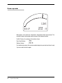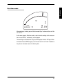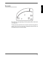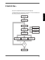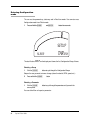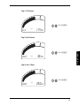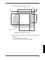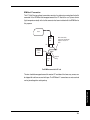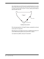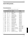
1
System 2
USER GUIDE
Pi System 2 User Guide
Part Number: 29K-071089-3E
Version 3.0, January 1999
Pi and the Pi logo are trademarks of Pi Group Limited
© Pi Research 1999
www.piresearch.com
1
Disclaimer
Pi Research makes no representation or warranties of any kind whatsoever with
respect to the contents hereof and specifically disclaims any implied warranties of
merchantability or fitness for any particular purpose. Pi Research shall not be
liable for any errors contained herein or for incidental or consequential damages in
connection with the furnishing, performance or use of the software, associated hardware,
or this written material.
Pi Research reserves the right to revise this publication from time to time, and to
make changes in the content hereof without obligation to notify any person of such
revision or changes.
A copy of the Pi Research Terms and Conditions of Sale is available on request, and
includes a declaration of the warranty and limitation of liability which apply to
all Pi Research products and services.
Health and Safety information
Under the terms of European and UK Health and Safety Legislation, Pi Research is
required to classify any hazardous materials in the products it supplies and to provide
relevant safety information to users.
Any hazardous materials in Pi products are clearly marked with appropriate symbols.
Product Safety Data Sheets relating to these materials are available on request.
2
System 2 User Guide
Contents
Introduction .............................................................................................. 7
About this User Guide .................................................................... 8
Overview
What is System 2? ................................................................................. 10
The dash ....................................................................................... 11
The Beacon kit .............................................................................. 12
The Club Expert PC software ....................................................... 13
Conventions ........................................................................................... 14
System 2 modes ..................................................................................... 15
Configuration mode ...................................................................... 15
Power up mode ............................................................................ 16
Real-time mode ............................................................................ 17
Race mode ................................................................................... 19
Telltale mode ................................................................................ 20
At the Track
Initial checks .......................................................................................... 22
Kit list ............................................................................................ 22
Checklists ..................................................................................... 23
A typical day… ....................................................................................... 25
Preparing for an outing ................................................................. 26
Driving the car .............................................................................. 27
Returning to the pits ..................................................................... 29
Switching off the car ..................................................................... 31
3
Configuring the dash
Settable parameters .............................................................................. 33
Configuration ................................................................................ 33
Configuration mode ............................................................................... 36
Entering Configuration mode ....................................................... 38
Alarms ........................................................................................... 41
RPM .............................................................................................. 41
Speed ............................................................................................ 42
Units .............................................................................................. 43
Name ............................................................................................ 44
Printer ........................................................................................... 44
Beacon .......................................................................................... 44
Engine Logbook ............................................................................ 45
Graph logging ............................................................................... 45
Outing type ................................................................................... 46
Using System 2
Real-time mode ...................................................................................... 48
Null Value ..................................................................................... 53
Turbo ............................................................................................. 53
Race mode .............................................................................................. 54
Alarms ........................................................................................... 56
Telltale mode .......................................................................................... 57
Lap Telltales ................................................................................. 58
Outing Telltales ............................................................................. 62
Printing Reports ..................................................................................... 63
Outings and resetting the dash ............................................................ 66
Data Loss ...................................................................................... 69
New track/New map ..................................................................... 70
Application Notes .................................................................................. 71
BMW M-System (1995) ................................................................ 71
Mazdaspeed Zytech ECM link ...................................................... 77
Lola F3000: 1994–5 ...................................................................... 81
4
System 2 User Guide
Rally and Hillclimb applications .................................................... 84
Karting applications ...................................................................... 87
Turbo and carburettor pressure measurement ............................ 88
System 2 video data link .............................................................. 90
Troubleshooting
Dash .............................................................................................. 93
Backlighting .................................................................................. 94
External buttons
and lights ...................................................................................... 94
Engine speed (RPM) .................................................................... 95
Speed ............................................................................................ 98
Lap times (Beacon) .................................................................... 101
Sensor readings – General ........................................................ 103
Temperatures ............................................................................. 103
Pressures .................................................................................... 104
Steering position ......................................................................... 105
Throttle position .......................................................................... 105
Battery ........................................................................................ 106
Accelerometer ............................................................................ 106
Data loss or data corruption ....................................................... 107
Telltales ...................................................................................... 108
Printing ........................................................................................ 109
Installation Notes
The installation kit ....................................................................... 111
Part A : Fitting the dash and sensors ................................................ 112
Wiring notes ................................................................................ 112
Wiring colour codes .................................................................... 112
Power supply .............................................................................. 113
Mounting the dash ...................................................................... 114
Wheelspeed measurement ........................................................ 117
RPM measurement ..................................................................... 120
Pressure measurement .............................................................. 128
Temperature measurement ........................................................ 130
Lap timing ................................................................................... 132
Optional sensors and interface boxes ........................................ 136
5
ABS sensor interface box ........................................................... 137
Waterspeed sensor .................................................................... 139
Wheelspeed selector box ........................................................... 141
Turbo/carburettor pressure sensor ............................................. 143
Rotary Potentiometer .................................................................. 144
Throttle sensor ............................................................................ 146
Linear potentiometers ................................................................. 147
Potentiometer interface box ....................................................... 148
Thermocouple sensor ................................................................. 150
Part B : Fitting the wiring loom .......................................................... 152
Connect the loom to the dash .................................................... 152
Lay the loom in the car ............................................................... 152
Secure unwanted sensor wires .................................................. 153
Cut the Loom to size .................................................................. 154
Fit the Sure-Seal connectors ...................................................... 155
Repeat the process for each sensor .......................................... 157
Fit the spade connectors ............................................................ 158
Fit the 4mm ring tags .................................................................. 158
Fit the 8mm ring tags .................................................................. 159
Fit the spiralwrap ........................................................................ 159
Reinstall the loom ....................................................................... 159
Waterproof the multiway connectors .......................................... 159
Part C: System checks and Power-up ............................................... 160
Check the installation ................................................................. 160
Turn the dash on ........................................................................ 160
Configure the dash ..................................................................... 161
Part D: The Auxiliary Connector ........................................................ 162
AUX Connector pin outs ............................................................. 162
Examples of use ......................................................................... 163
Part E: Wiring details ........................................................................... 165
Dash wiring Information .............................................................. 165
Connector wiring ......................................................................... 167
Contact information ............................................................................. 170
6
System 2 User Guide
Introduction
Welcome to the Pi System 2 User Guide. This Guide is the core documentation for the
installation and use of Pi System 2.
References are made in this Guide to the Club Expert PC (Personal Computer) software,
which can be used with most laptop computers. The Club Expert software allows you to
compare the performance of both the car and the driver to previous outings, or outings
from another car.
This Guide has been divided into sections to help you become familiar with the system
quickly and easily.
If System 2 has already been fitted to your car, you can get a general idea of the features
available within each operating mode (Race mode, Telltale mode, etc.) by looking at the
‘Overview’ section. A summary of how System 2 is likely to be used in practice is given in
the section ‘At the track’.
If you are installing System 2 yourself, you will need to follow the instructions given in the
‘Installation notes’ section before proceeding.
The User Guide is divided into the following sections:
Overview
At the track
Configuring the dash
Using System 2
Troubleshooting
Installation notes
7
About this User Guide
This version of the System 2 User Guide covers dash features up to dash version 3.80. It
includes details of sensors available for use on the two User channels.
The User Guide also includes application notes for a number of specific racing
applications, such as rallying and karting. There are also notes for cars that have
sequential gearboxes or with serial data streams available on their engine management
systems.
8
System 2 User Guide
Overview
Overview
SYSTEM 2 USER GUIDE
What is System 2?
This section gives an overview of System 2, its features, variants and configuration
modes.
Read this section before you use System 2 as an engineer or driver. You will also find it
useful to refer to it at the beginning of each race, until you are thoroughly familiar with the
system.
System 2 is an integrated digital dashboard and data logger.
Each System 2 includes:
■
■
■
■
■
■
■
■
a dash,
a car loom,
a wheel speed sensor,
an RPM box,
two temperature sensors,
two pressure sensors,
an installation kit, and
a System 2 User Guide.
The following options are available:
■
■
■
■
■
■
■
10
System 2 User Guide
backlighting,
external buttons and warning lights,
ECM links (to Engine Management Systems),
a Beacon kit,
Club Expert series of software for data analysis,
Additional sensors for the two User channels, and
an interface for monitoring sequential gearbox position.
The dash itself forms the central part of System 2. Included in the dash is the digital
display, logging memory, two control buttons, back-up battery, accelerometer (for g-force),
dash temperature sensor and a power supply for the sensors.
The dash has been designed to monitor, display and log the following parameters:
■
■
■
■
■
■
■
■
■
■
■
Speed
RPM
Lap times (Beacon kit required)
Oil temperature
Water temperature
Dash temperature
Oil pressure
Fuel pressure
Car battery voltage
Cornering g-force
User channel 1 & 2.
The dash also has two lights on the front panel: an over-rev light (or gear-change light)
that comes on when the RPM goes over the red line, and an Alarm light that flashes if any
of the sensors exceed preset alarm thresholds.
Logged data can be viewed on the dash or downloaded to a printer, or to a computer (with
optional Club Expert series of software).
11
Overview
The dash
The dash normally logs for up to 42 minutes. However, by reducing the logging rate, a
maximum of 105 minutes can be logged before the memory in the dash fills up. See the
section ‘Configuring the dash’, for details.
The User channels can be used to measure a range of parameters:
■
■
■
Thermocouples for measuring Exhaust Gas Temperature (EGT);
Temperatures for additional gearbox or differential temps;
Potentiometers for steering or throttle position.
The fuel and oil pressure channels can also be configured to measure lower turbo or
carburettor pressures (0–40psi).
The Beacon kit
The Beacon kit provides the following benefits:
■
■
■
■
Fixed lap times or elapsed stage times
Lap counter
Lap time telltales
Lap markers for the Club Expert series of software.
The Beacon kit allows an accurate registration of each lap passed. The kit consists of an
infrared detector mounted on the car and an infrared transmitter mounted on the pit wall.
As the car passes the transmitter, the infrared signal is picked up by the detector on the
car. The dash immediately displays the lap time for the driver, as well as storing
information for each lap for later analysis with the Club Expert series software.
As well as displaying the time and count for each lap, the Beacon kit enables System 2
to store and display the maximum/minimum readings for each of the sensors per lap (the
telltales).
If you are intending to use the Club Expert range of software, you will need a Beacon kit,
since the software displays data by lap.
12
System 2 User Guide
A powerful feature of System 2 is the data analysis software that can be run on a laptop
PC. The Club Expert range of PC software (Club Expert plus , Club Expert super and
Corner Analysis Program (CAP)) offers a wide range of features, including:
■
■
■
■
■
■
■
■
■
Circuit maps
Graphs of RPM and speed
Lap-by-lap reports on pressures, temperatures, voltage and Dash
temperature
Graphs of lateral g-force
Information about the track, driver and date
Speed reports that compare performance with other cars or drivers
An RPM logbook kept over the life of the engine
An archiving facility for saving logged data on floppy discs for future
analysis
Full printing facilities.
When plugged into the car at the end of an outing, the software transfers (i.e. downloads)
all the data stored in the dash. This data can then be used as the basis of a series of
reports. For example, while the car prepares for its next outing, you can be comparing lap
times for different suspension settings, tyres, or even drivers.
Club Expert plus can also provide split time reports, on-power histograms, compare
elapsed time, gear ratio, in-line g and graphs of analog channels.
Club Expert super allows the use of Set-up and Running sheets, multiple graphing,
beacon move facility, overlaid histograms, animation, and configurable lap threshold.
Corner Analysis Program (CAP) uses steering, speed and acceleration channels to
produce a Speed Influence graph, Steering Sensitivity, Intra-corner behaviour graph, map
report and g-g diagram.
13
Overview
The Club Expert PC
software
Conventions
RPM telltale
Redline marker
RPM bargraph
Overrev
LED
SPEED
MAX
LAP TIME
(MODE/LAP)
57 KPH
SPEED
MIN
45.91
button
159
Lap times or parameter names
BUTTON PRESS
0.5
EXAMPLE
1
1.5
2
Click (CHANNEL) to cycle through
Pages in Real-time mode
Click
Press and Hold both (CHANNEL)
and (MODE/LAP) to enter
Configuration mode
Press and Hold
Double click (MODE/LAP) for Reset
option
Double click
Definitions of button presses
14
System 2 User Guide
(CHANNEL)
button
Parameter readings
TIME (seconds)
0
Alarm
LED
The dash automatically switches into one of four different operating modes depending on
whether the car is stationary, is being driven, or has just returned from an outing. These
operating modes are:
■
■
■
■
Power up mode,
Real-time mode,
Race mode, and
Telltale mode.
In addition to the four normal operating modes, a Configuration mode exists for you to
adjust alarm thresholds (e.g. for low oil pressure or high oil temperature), the RPM red line
setting and the other parameters.
Configuration mode
System 2 is preprogrammed with default settings, but it may be necessary to alter these
values to suit your car.
Some of these parameters only need to be set once when System 2 is installed. However,
you may wish to adjust parameters such as the RPM over-rev light or the battery voltage
alarm level more frequently.
Details of how to configure System 2 are given in the ‘Configuring the dash’ section of this
guide, together with a list of the parameters you can change.
15
Overview
System 2 modes
Power up mode
1041
SYS–2P
3.70
F3
When power is first switched on, information is displayed for about three seconds. This
includes the dash serial number and the version of the software installed.
On Mk.II Dashes, the readings will be similar to these:
Dash Serial Number
Software Version
1041
3.70 F3
You should make a note of the version number displayed on your dash and have it ready
if you ever need technical support.
16
System 2 User Guide
Overview
Real-time mode
SPEED
MAX
LAP TIME
0.00.00
SPEED
MIN
0
0
MPH
After powering up, the dash goes into Real-time mode Page 1 and remains there until the
car is driven.
As the name suggests, Real-time mode is used to show the readings of the sensors on
the car in real time (i.e. continuously), as they happen.
The word Page is used to describe a single screen display on the dash. All Pages in Realtime mode include the RPM bar graph, red line marker and max-rev marker in addition to
the particular information listed in the following table.
17
Real-time Pages
18
Page 1
Lap time (Beacon kit required)
Max. Speed
Min. Speed
Page 2
Lap time
Lap number
Current speed
Page 3
RPM (digital)
Page 4
Current Speed
Latched speed
Page 5
Water temperature
Page 6
Oil temperature
Page 7
Oil pressure
Page 8
Fuel pressure
Page 9
User 1
Page 10
User 2
Page 11
Box (dash) temperature
Page 12
Battery voltage
System 2 User Guide
Overview
Race mode
SPEED
MAX
LAP TIME
45.91
SPEED
MIN
159
57 KPH
Race mode has the same display Pages as Real-time mode, but differs in that the dash
is also logging data.
The dash enters Race mode when the car exceeds its minimum outing speed, for
example, 40 mph. Once the car starts moving, it automatically switches to Page 1 and
starts displaying maximum and minimum speeds.
19
Telltale mode
LAP #
LTIME
5
39.4
SEC
When you return to the pits after driving the car around the track, the dash detects that
you have come to a stop.
Three seconds later, the dash switches to Telltale mode to show you the most important
information about the outing you’ve just completed.
In Telltale mode, the lap number and lap time for the fastest lap (assuming a Beacon is
being used) are displayed.
Telltale mode displays the following information for each lap:
■
■
■
■
■
■
■
■
■
■
■
20
System 2 User Guide
Lap time
Max. RPM
Max. Speed
Max. Water temperature
Max. Oil temperature
Min. Oil pressure
Min. Fuel pressure
Max. User 1
Max. User 2
Min. Battery voltage
Max. Box temperature.
At the Track
At the Track
SYSTEM 2 USER GUIDE
Initial checks
This section takes you through a typical day of using System 2.
If you have not used System 2 before, you may need to refer to the ‘Configuring the dash’
and ‘Using the dash’ sections.
Kit list
For a typical day using System 2,
If you have a Beacon kit, you will need:
■ the Beacon transmitter and power lead,
■ a 12V battery to run the Beacon transmitter.
If you use a printer, you will need:
■ the printer,
■ printer paper,
■ a power lead or battery,
■ the System 2 printer lead.
If you have the Club Expert PC software, you will need:
■ your laptop computer, (with Club Expert installed)
■ a recharger or a spare battery,
■ the System 2 computer lead,
■ some formatted floppy discs for backing up data.
In case of accident damage, we suggest you have:
■ a basic toolkit (including crimping tool and System 2 insertion tool)
■ some spare System 2 connectors,
■ a spare wheel speed sensor,
■ a spare temperature sensor,
■ a spare pressure sensor.
22
System 2 User guide
Checklists
At the Track
Before each outing, check that:
■ the dash is powered up
■ the dash has been reset
■ the dash has been configured properly for the car
■ the sensors are working properly (Click the (CHANNEL) button to check each
sensor value, e.g. car battery voltage or steering position)
■ the wheel speed sensor is adjusted correctly (spin the wheel)
■ the sensor wiring has not been damaged, if you’ve been working on the
car.
If you have a Beacon kit, check that:
■ the Beacon transmitter is wired up and working (check the front light on the
transmitter)
■ the transmitter and detector are set to the same channel
■ the Beacon detector is working (wave the transmitter in front of it and make
sure the lap times change)
■ the transmitter is placed on the pit wall at the same height as the detector
■ the battery is fully charged
■ you’ve remembered to pick up the transmitter after the race!
NOTE: The lap times are stored in the dash, not in the Beacon transmitter. This means
that all the cars in your team can use the same Beacon channel with a single
transmitter.
Each time you visit a circuit, try to place the transmitter at exactly the same place on
the pit wall. This will ensure that graphs produced by the Club Expert PC software from
different visits to the same track align.
A master Beacon transmitter is installed at major tracks in the UK. The beacon
transmitter is set to channel 0. To use this transmitter you must set your beacon
detector to channel 0. You do not then need to use your own beacon transmitter.
23
If you use a printer, check that:
■ the printer is turned on
■ paper has been loaded
■ the System 2 printer lead has been plugged in
■ the dash has been properly configured for your particular printer
■ the printer has been properly configured for use with System 2 (see the
‘Configuring the dash’ section).
If you have the Club Expert PC software
■ Before you leave for the track, make sure that the laptop has been fully
recharged. Most monochrome laptops can run on batteries for about two
hours.
■ If this is your first visit to a particular track, run the software and enter the
track name.
■ Remember to enter the driver and outing details once you have
downloaded data from an outing.
■ Wait for the dash to power up (about three seconds) before plugging in the
computer lead.
■ If you do not want to download a certain outing to the computer, reset the
dash to avoid it filling up with data.
■ The data you get from the car may be valuable and you should back-up the
outings onto floppy discs on a regular basis (see the Club Expert PC
Software Guide on the subject of archiving data).
24
System 2 User guide
A typical day…
Once you have completed the check lists, you are now ready to go.
At the Track
The diagram below shows a typical day’s use of System 2. (The unit will normally have
been correctly installed and configured for your car.)
Install the dash
Configure the dash
Prepare for outing
Alarms?
Drive the car
Battery failure?
Spin off?
Return to the pits
Inspect telltales
Print telltales
Yes
Download to PC
Another
outing?
No
Switch off the car
25
Preparing for an outing
Powering up the dash
Turn on the master switch (and ignition switch, if necessary) to power up the dash. The
dash changes from Power up mode to Real-time mode.
Check configuration
The first time you use the dash, check that it is correctly configured (see the ‘Configuring
the dash’ section).
Warming up the car
1. Press the starter button to fire up the engine.
Use the dash to monitor temperatures and pressures whilst you warm the car up in the
pits.
2.
Click the (CHANNEL) button to cycle through the different Pages.
(The dash does not log data at this point.)
Resetting the dash
If you want to log data, make sure the dash has been reset the first time you go out on a
new track.
1.
2.
Double Click the (MODE/LAP) button.
Click the (CHANNEL) button to erase data.
NOTE: If you use a laptop computer, the dash is reset automatically whenever you
download logged data.
26
System 2 User guide
Driving the car
The car is now ready to drive.
1.
Press and Hold the (CHANNEL) button to switch to Page 1.
As you leave the pits and pass the outing speed, the dash starts logging. Page 1 shows:
the RPM,
the maximum straight line speed,
the minimum cornering speed, and
lap times.
Click the (CHANNEL) button to display Page 2.
At the Track
■
■
■
■
2.
Page 2 shows:
■
■
■
the RPM,
the lap number
the lap time.
To return to Page 1 at any time:
3.
Press and Hold the (CHANNEL) button.
The RPM bar graph
The RPM bar graph appears on all of the Pages, and has some useful features:
■
■
■
An adjustable “red line” marker. Some drivers use this as a gear-change
indicator.
When the RPM exceeds the red line, both the bar graph and the over-rev
light flash.
A telltale marker shows the highest RPM reached. This can be cleared by
Clicking the (MODE/LAP) button while the car is being driven.
Lap Times
As you drive past the Beacon transmitter on the pit wall, the time for your last lap appears
on the display. Page 2 also shows a lap count.
Latched Speed
With the current road speed displayed on Page 4, Click the (MODE/LAP) button. This latches
the current speed.
27
NOTE: External buttons can be fitted to the steering wheel as an option.
Spinning off
If you spin off the track and restart quickly, System 2 continues to log data.
If you spin off and stop for more than three seconds, the display switches into Telltale
mode (the system cannot distinguish between a pit stop and a spin). When you get back
onto the track, the display switches back into Race mode automatically and adds data to
that already logged.
Alarms
An important feature of System 2 is its ability to warn you if there is anything wrong with
the parameters it is monitoring (e.g. loss of oil pressure).
The thresholds at which the alarms go off are set in Configuration mode.
If an alarm condition is detected, the Alarm light goes on and a message appears on the
screen. If the alarm comes on, and stays on (e.g. there is an oil leak):
1.
Click either button to reset the alarm.
The alarm thresholds are adjusted for the remainder of the outing, to prevent them from
re-triggering immediately. If the problem (e.g. low fuel pressure) is temporary, the alarm
will reset itself and the threshold will not be adjusted.
NOTE: After a manual reset, alarm thresholds are reset to their original value only
when the dash is reset.
Battery Failure
System 2 requires a minimum battery voltage (9V) in order to operate. If the car battery
delivers less than this, the dash will anticipate a power failure and will save the data
logged so far.
The Battery Alarm will alert you when the battery is running low. From then on (until the
car stops) the dash will display information as usual but will not attempt to log it.
28
System 2 User guide
NOTE: Each time you come into the pits YOU MUST ALLOW THE CAR TO STOP
FOR 3 SECONDS before killing the power to the dash – otherwise data will not be
recorded.
On dash versions 3.49 and above, the Alarm light flashes twice when it is safe to switch
off the dash.
Inspecting telltales
When you stop, and have the dash powered up, the lap number and time for the fastest
lap are displayed.
NOTE: Depending on the way the dash is configured, you may have to Press and Hold
the (MODE/LAP) button to manually select Telltale mode.
1.
Click the (CHANNEL) button.
This cycles through the following telltales for the fastest lap:
■
■
■
■
■
■
■
■
■
■
■
Lap time
Max. RPM
Max. Speed
Max. Water temperature
Max. Oil temperature
Min. Oil pressure
Min. Fuel pressure
Min. Battery voltage
Max. User 1
Max. User 2
Max. dash temperature
29
At the Track
Returning to the pits
2.
Click the (MODE/LAP) button to change the lap.
This cycles through the telltales (maximum and minimum values) for each lap, and for the
outing as a whole, in the following sequence:
■
■
■
■
3.
the Out lap
Lap #1, lap #2, lap #3…
the In lap
the outing (except that no lap time is given for the outing as a whole).
Press and Hold the (CHANNEL) button to select the outing values.
Printing telltales directly from the dash
1. Make sure your printer is powered up and is loaded with sufficient paper.
2. If the dash is in Real-time mode, Press and Hold the (MODE/LAP) button to
return to Telltale mode.
3. Plug the System 2 printer cable into the Communication port on the car.
After a short delay, the data is printed out. Refer to the section ‘Using the System 2’ for
details on printing.
Downloading to a laptop PC
To download data from the dash to a laptop computer:
1.
2.
3.
4.
Have your laptop powered-up and running the Club Expert PC software.
Select the track from the existing list, or enter the name for a new track.
Plug the computer lead into the 9-pin serial port on the back of the laptop.
Plug the other end of the computer lead into the communication port on the
car.
A bar graph is displayed on the bottom of the computer screen to indicate the proportion
of data transferred so far. DO NOT REMOVE THE LEAD from the car until the bar graph
has completely filled up.
You can now exit the program and turn off the laptop, or analyse the data further. Because
you have downloaded the data, the dash resets itself for the next outing.
See the Club Expert PC Software Guide for details of how to use the analysis software.
30
System 2 User guide
Switching off the car
Once the car has come into the pits and the dash has stored its data (i.e. when the Alarm
LED flashes), it is safe to turn off the dash.
A note on Outings
In general, an Outing is defined as the time a car spends between leaving the pits and
returning to the pits at the end of the race or practice.
To avoid the dash being reset if your car spins off and stops on the track, data continues
to be logged until either:
■
■
■
■
the dash fills up with data;
the data is downloaded to a laptop PC;
the data is printed out; or
the dash is manually reset.
Data logging is triggered by exceeding a preset road speed (for example, 40 mph). This
avoids filling up the dash with unwanted data before you start the race or practice laps.
31
At the Track
Data from the outing is retained in the dash by a small internal battery and may be printed
or downloaded to a computer at any time before the next outing.
Configuring
the dash
Settable parameters
This section describes in detail how to configure the dash. You will need to do this when
you first install System 2. You may also wish to adjust alarm thresholds when you are
more familiar with the System.
To allow System 2 to be used on a wide range of cars, there are a number of parameters
that can be adjusted to your particular requirements.
Configuring
Some of these parameters only need to be set once, when System 2 is installed. However,
you may wish to adjust parameters such as the RPM over-rev light or battery voltage
alarm level more frequently.
Configuration
The parameters, their range and defaults are listed in the following table.
Setup
Min.
Max.
Default
0
10
10
0
10
10
9
200
150
150
200
999
999
20
20
105
105
20
105
105
10.5
Alarms
Oil pressure (psi or TURB1)
Oil temperature (°C)
Water temperature (°C)
Fuel pressure (psi or TURB2)
User 1
User 2
Battery voltage (volts)
33
Setup
Min./Options
Max.
Default
20,000
16
19,500
6,500
4
7,500
A
Yes
Off
0.01
RPM
Red line (rpm)
Pulse (4 stroke)
Max. scale (rpm)
Pulse type
Flashing telltale
Spike filter
Over rev light duration
0
1
3,500
A/B/C/D
Yes/No
Off/3/7
0.01
2.0
Speed
Tyre diameter (mm)
Triggers (per rev)
Outing start speed
30
1
0,2,20,40,80,112
999
100
535
2
112
Units
Speed
Oil/Water temperature
Fuel pressure
Oil pressure
User 1
User 2
Tyre diameter
KPH/MPH
°C/°F
psi/KGF/bar/Tbar
psi/KGF/bar/Tbar
°C/°F/VLT/°CT
°C/°F/VLT/°CT
mm/inches
KPH
°C
psi
psi
°C
°C
mm
Name
User 1
User 2
34
System 2 User Guide
5 character alphanumeric
5 character alphanumeric
USER1
USER2
Setup
Options
Default
Printer
Printer type
Basic/Paintjet/Diconix/IBM
Basic
Beacon
Beacon fitted
Mode
No/Yes
Fix/Run
No
Fix
Reset
Keep
Configuring
Engine logbook
Keep/Reset
Logging
Rate
Accel
User 1
User 2
Oil pressure (or Turbo 1)
Fuel pressure (or Turbo 2)
Water temperature
Oil temperature
Battery voltage
Fast/Slow
Yes/No
Yes/No
Yes/No
Yes/No
Yes/No
Yes/No
Yes/No
Yes/No
Fast
Yes
No
No
No
No
No
No
No
Auto/Manual/Rally
Auto
Outing type
Outing Type
35
Configuration mode
The table below shows how Parameter values are organised in Configuration groups. The
table on the facing page summarises the dash button operations for editing parameter
values in Configuration mode.
Configuration groups
Parameter values
ALARMS
RPM
Redline/ Pulses/ Max. scale/ Pulse type/ Flashing telltale/ Filter/ Light
SPEED
Tyre diameter/ Triggers/ Outing speed
UNITS
Speed/ Temperature/ Fuel Pressure/ Oil Pressure/ User 1/ User 2/ Tyre diameter
NAMES
User 1/ User 2
PRINTER
Printer type
BEACON
Beacon fitted/ Mode
LOGBOOK
Reset
LOGGING
Rate/ Accelerometer/ User 1/ User 2/ Oil pressure/ Fuel pressure/ Water temp./ Oil temp./ Battery
OUTING
36
Oil pressure/ Oil temp./ Water temp./ Fuel pressure/ User 1/ User 2/ Battery
Type
System 2 User Guide
NOTE: Repeat the steps for configuring parameter values as often as necessary before
saving the current settings. We suggest you configure the Unit parameters first.
To do this:
Do this:
Enter Configuration mode:
Press and Hold (CHANNEL) and (LAP/MODE)
buttons together
Step through Configuration groups:
Click (CHANNEL)
Inspect or alter a Configuration group:
Press and Hold (CHANNEL)
Step through Parameter values:
Click (CHANNEL)
Increment values:
Click (LAP/MODE)
Auto-adjust values:
Press and Hold (LAP/MODE)
Save the current settings within each
Configuration group:
Press and Hold (CHANNEL)
Save all current settings:
Press and Hold (CHANNEL) and (LAP/MODE)
buttons together
Configuring
WARNING: Changing configurations may cause data to be erased. Only enter
Configuration mode after you have inspected or downloaded data from any
previous outings.
37
Entering Configuration
mode
The car must be powered up, stationary and in Real-time mode. You cannot access
Configuration mode from Telltale mode.
1.
Press and Hold the (CHANNEL)
and (MODE/LAP)
buttons for two seconds.
SETup
THRESH
ALARM
The dash flashes SETUP on the display and shows the first Configuration Group, Alarms.
Selecting a Group
1. Click the (CHANNEL)
button to cycle through the Configuration Groups.
Stop on the one you want to view or change (alarm thresholds, RPM, speed, etc.).
2.
Press and Hold the (CHANNEL)
Selecting a Parameter
1. Click the (CHANNEL)
one required.
button.
button to cycle through the parameters until you reach the
You can either Alter or Inspect a parameter:
38
System 2 User Guide
Altering a parameter
There are two ways to change the value of a parameter once you have selected it: Step
mode and Auto-adjust mode.
Step mode
Step mode is most suited to values that have a small range, or only switch from Yes to
No.
1.
Click the (MODE/LAP)
a time.
button to increment the value of a parameter one step at
This mode is most suited to values that have a wide range of values, such as
temperatures, tyre sizes or user channel name.
1.
First Press and Hold the (MODE/LAP)
button.
If auto-adjust is available for a parameter, the digits will start to flash between ‘0’ and ‘9’.
SET
RLINE
2.
Click the (MODE/LAP)
with the left-most digit.
072 00
button to freeze each digit at its correct value, starting
Once all the digits have been frozen, auto-adjust mode ends automatically.
NOTE: In Auto-adjust mode, if you try to set a value below the minimum permitted
value, it will be set at the minimum. Similarly, any value set above the maximum value
will be set to the maximum permitted value.
39
Configuring
Auto-adjust mode
To Inspect or Change other parameters in the Group
1. Click the (CHANNEL)
button
To Return to the Configuration Groups
1. Press and Hold the (CHANNEL)
button to return to the Configuration Groups.
You can then select another Group of parameters or leave Configuration mode.
To Leave Configuration mode
To save the parameters and exit from Configuration mode:
1.
2.
Return to the main Configuration Groups.
Press and Hold the (CHANNEL)
and (MODE/LAP)
buttons for two seconds.
The dash momentarily displays the word Saved.
SAVED
To Exit without saving changes
If you make a mistake or change your mind, you can restore the previously stored settings
by switching off the dash (e.g. with the master switch) before exiting Configuration mode.
40
System 2 User Guide
Alarms
You must set the values for the following parameters as the highest value allowable before
an alarm is triggered:
■
■
■
■
Oil temperature
Water temperature
User 1
User 2
■
■
■
Oil pressure (or Turbo 1)
Fuel pressure (or Turbo 2)
Battery voltage
NOTE: If either pressure channel is configured as a turbo channel, the alarm LED can
be set to come on when the turbo drops below a given value.
RPM
Detailed instructions on setting up the RPM are included in the Installation Notes.
Red line
The RPM for the red line marker on the display. This should be less than the SCALE
setting (see below).
Pulse
The number of ignition pulses per TWO revolutions of the engine.
Max. Scale
This parameter is generally fixed by the markings on the display. However, it can be
adjusted in steps of 1000 RPM by using adhesive overlays.
41
Configuring
You must set the values for the following parameters as the lowest value allowable before
an alarm is triggered:
Pulse type
The Pulse type can take values A, B, C or D. Use type D with the Pi RPM box. If you are
using a signal directly from an ECM (Engine Control Module), you may need to select a
different type. If you are having problems with the RPM, check the setting on the RPM Box
as well (see the ‘Installation Notes’ section).
Flashing telltale
Switches the flashing marker on the bar graph On or Off.
Spike Filter
Although normally unnecessary, the dash can filter out spikes on tacho signals from
ignition systems.
Overrev Light Duration
Sets how long the over-rev light stays on.
Speed
Tyre diameter
Sets the tyre diameter on which the wheel speed trigger is mounted (in millimetres or
inches).
NOTE: Take special care in measuring the tyre diameter since this setting affects the
accuracy of all speed readings.
Triggers
Sets the number of speed triggers that are fitted on the wheel.
42
System 2 User Guide
Outing start speed
Sets the speed that must be exceeded before logging starts. This will vary according to
your car, but should be greater than the speed reached when you drive around the pits
or garage areas.
Wheel trigger indicator
(Dash version 3.49 or higher) When on Speed settings, the alarm light will flash when the
wheel speed sensor detects its trigger. This feature will help you check the setting of the
sensor.
The following parameters may be measured in various units. Select the ones you prefer
when configuring the dash for the first time.
Speed
Set the Speed units to either miles per hour (mph) or kilometres per hour (kph).
Oil/Water Temperature
Set the Temperature units to either Celsius (°C) or Fahrenheit (°F).
Fuel Pressure
Set the Pressure units to either pounds per square inch (psi), 100,000N/m2 (bar), kilogram
force (kgf), or Tbar (bar) for turbo sensors (0 to 2.5 bar).
Oil Pressure
Set the Pressure units to either pounds per square inch (psi), 100,000N/m2 (bar), kilogram
force (kgf), or Tbar (bar) for turbo sensors (0 to 2.5 bar).
User 1
Set the User 1 channel to measure either temperature (C° or °F), voltage (VLT), or
thermocouple temperature (°CT).
43
Configuring
Units
User 2
Set the User 2 channel to measure either temperature (C° or °F), voltage (VLT), or
thermocouple temperature (°CT).
Tyre diameter
Set the tyre diameter units to either millimetres (mm) or inches (inches).
Name
You can assign your own names to channels User 1 and User 2. Using Auto-adjust mode,
you can set each digit to be A–Z, 0–9 or blank.
Printer
Printer type
If you intend to print data directly from the dash, you will require a printer with a serial
interface. Set the Printer type to be the same as the make or emulation mode of the
printer.
Beacon
Beacon fitted
If you have the Beacon kit installed, set this option to YES to detect Beacon pulses.
Mode
The lap timer can be configured to show the lap time for the previous lap (Fix), or as a
running timer (Run).
44
System 2 User Guide
Engine Logbook
The Logbook records the history of an engine from the time it is reset. This data is only
available by using the Club Expert PC software. If you change the engine in your car,
select Reset with the (MODE/LAP) button.
Graph logging
Rate
Rate
Fast
Slow
Configuring
This selects a fast or slow logging rate for the speed and RPM data. Fast logging gives
better resolution on the Club Expert PC software; slow logging doubles the logging time.
Samples per second
Speed
10
5
RPM
20
10
NOTE: Other parameters (i.e. Oil pressure) are sampled at the same rate as speed
(e.g. 5 or 10 samples per second).
Accel
Once you have made a map of a track with the Club Expert PC software there is no longer
any need to log lateral acceleration (cornering g-force), unless you are using the
Cornering Analysis Program (CAP). If are using CAP you must log Accel all the time.
To increase logging time, you can stop the dash from logging data from its internal
accelerometer.
Acceleration
Yes
No
Logging time (minutes)
Fast
42
52
Slow
84
104
45
Graph Logging
When used with Club Expert plus, you have the option of being able to produce graphs
for any of the following channels:
■
■
■
■
■
■
■
User 1
User 2
Oil pressure (or Turbo 1)
Fuel pressure (or Turbo 2)
Water temperature
Oil temperature
Battery voltage
Outing type
Type
■ On Manual setting, the dash is reset as normal, e.g. when a printer or PC is
plugged into the computer, or when the dash is manually reset.
Use this mode if you are using the Club Expert software on a regular basis.
■ On Auto setting, the dash is also reset at the beginning of the day when the
engine temperatures are cold. This saves you from having to manually
reset the dash and will prevent the MAX. indicator flashing when the dash
is full.
■ On the Rally setting, the dash behaves as in Auto, but also:
– the dash does not automatically enter Telltale mode when the car stops;
– the start logging criteria change to outing speed and 20% of RPM redline,
as opposed to 40%;
– to stop logging, the dash must see zero speed for 10 seconds, as
opposed to 3 seconds.
46
System 2 User Guide
SYSTEM 2 USER GUIDE
Using System 2
Using System 2
Real-time mode
This section gives you step-by-step instructions on how to use the dash. It can be used
for reference once you have understood the concepts described in the sections ‘Overview’
and ‘At the Track’.
Real-time mode displays the same information as Race mode, except that the data is not
stored. Once you exceed the outing speed, the system automatically switches to Race
mode and begins logging data.
CHANNEL button
The (CHANNEL) button is used to move through the different Pages to display the values
recorded by the various sensors.
■
■
Click the (CHANNEL) button to cycle through the Pages.
Press and Hold the (CHANNEL) button to return to Page 1.
MODE/LAP button
■ Press and Hold the (MODE/LAP) button to switch to Telltale mode. (Note: this
only works after the car has been driven, and is stationary.)
■ Double Click the (MODE/LAP) button for Reset options.
The 12 Real-time mode Pages display data as follows:
48
System 2 User Guide
Page 1: Lap time, max. and min. speed
SPEED
MAX
166
LAP TIME
24.29
Click (CHANNEL)
0 MPH
SPEED
MIN
Page 2: Lap time, lap number and current speed
LAP TIME
24.29
SPEED
2
Click (CHANNEL)
Using System 2
LAP #
0 mPH
Page 3: RPM
Click (CHANNEL)
RPM
NOW AT
52 48
49
Page 4: Speed
0
SPEED
NOW AT
Click (CHANNEL)
0 MPH
Page 5: Water Temp
Click (CHANNEL)
water
NOW AT
75 o C
Page 6: Oil Temp
Click (CHANNEL)
OIL-T
50
System 2 User Guide
NOW AT
105 o C
Page 7: Oil Pressure
Click (CHANNEL)
OIL-p
NOW AT
114 psi
Page 8: Fuel Pressure
FUELp
NOW AT
Using System 2
Click (CHANNEL)
86 psi
Page 9: User 1 (Steer)
Click (CHANNEL)
STEER
NOW AT
2.50VLT
51
Page 10: User 2 (EGT)
Click (CHANNEL)
EGT
560 o CT
NOW AT
Page 11: Battery Voltage
Click (CHANNEL)
batt
NOW AT
11.3 vlt
Page 12: Box Temperature
bxtmp
52
System 2 User Guide
NOW AT
31 o c
Null Value
If a sensor has not been connected, a null value is displayed. In the example below, the
fuel pressure sensor is not connected.
No Fuel pressure
---
PSI
Turbo
If the oil or fuel pressure channels are configured for a turbo sensor they are displayed
as follows:
Turbo
TURB1
NOW AT
2.00 TBR
53
Using System 2
NOW AT
FUELP
Race mode
Race mode is similar to Real-time mode except that data logging takes place during Race
mode (this is triggered by driving the car above its outing speed).
The CHANNEL button
■ Click the (CHANNEL)
button to cycle through the Pages.
■ Press and Hold the (CHANNEL)
button to return to Page 1.
The MODE/LAP button
■ Click the (MODE/LAP)
■ Click the (MODE/LAP)
(when on Page 4).
Alarms
■ Click the (MODE/LAP)
button to reset the RPM telltale.
button to latch the current road speed
or (CHANNEL)
buttons to clear anAlarm signal.
Page 1: Lap time, max. and min. speed
SPEED
MAX
LAP TIME
49.21
54
System 2 User Guide
SPEED
MIN
191
72 kPH
Click (CHANNEL)
Page 2: Lap time, lap number and current speed
LAP #
LAP TIME
49.21
SPEED
2
Click (CHANNEL)
128 kPH
Page 4: Speed
107
SPEED
NOW AT
Using System 2
Clicking the (MODE/LAP) button on the Speed Page latches the current road speed.
Click (MODE/LAP)
128 kPH
55
Alarms
System 2 has been specially designed to trigger an alarm if any of the following
parameters are exceeded:
■
■
■
■
■
■
Max. Water temperature
Max. Oil temperature
Min. Oil or turbo pressure
Min. Fuel or turbo pressure
Max. User 1 or User 2 values
Min. Battery voltage
After an Alarm has been generated, the thresholds are adjusted (until the dash has been
reset), preventing alarms from retriggering after a spin:
■
■
■
Temperature +5°C
Pressures –5 psi
Voltage –0.5 volts
Alarm prevention
To prevent alarms being set off unnecessarily, they are only triggered when:
■
■
the RPM goes above 40% of the red line (i.e. the engine attains 3600 RPM
for a car with a red line set at 9000 RPM), or
the car has been moving for more than 30 seconds.
Adjusting Alarms
You can adjust the Alarm thresholds when the dash is in Configuration mode; see the
‘Configuring the dash’ section.
User channels
User channels are alarmed for use with temperature or thermocouple sensors. If you are
using voltage readings for steering or throttle position, you should set alarm thresholds
in excess of 5.5 volts to prevent the alarms being triggered.
56
System 2 User Guide
Telltale mode
The dash automatically enters Telltale mode after the car has been driven and has come
to a standstill for more than three seconds.
NOTE: Dash version 3.33 and below also require zero RPM before entering Telltale
mode automatically. On these dashes you can select Telltale mode with the (MODE/LAP)
button while the engine is still running.
The CHANNEL button
■ Click the (CHANNEL) button to cycle through max. and min. values for the
current lap or outing.
■ Press and hold the (CHANNEL) button to see the telltales for the whole
outing.
Using System 2
The MODE/LAP button
■ Click the (MODE/LAP)
button to move to the next lap or outing.
■ Press and hold the (MODE/LAP)
button to switch between Real-time and
Telltale mode.
■ Double Click the (MODE/LAP)
button for Reset options.
NOTE: The first lap driven in an outing is always called the Out lap. The last lap driven
in an outing is always called the In lap.
Version 3.49 and above:
If a car enters and leaves the pits in the middle of an outing, the entry lap is called the
Pit lap and the exit lap is the Start lap.
57
Lap Telltales
Default Page (Fastest lap time)
LAP #
4
Click (CHANNEL)
34.6 SEC
LTIME
Max. RPM
LAP #
RPM
58
System 2 User Guide
MAX
5
Click (CHANNEL)
97 15
Max. Speed
LAP #
speed
5
MAX
Click (CHANNEL)
126 mph
LAP #
water
5
Using System 2
Max. Water temperature
Click (CHANNEL)
96 o c
MAX
Max. Oil temperature
LAP #
oil-t
MAX
5
Click (CHANNEL)
81 o c
59
Min. Oil pressure
5
LAP #
oil-p
Click (CHANNEL)
67 psi
MIN
Min. Fuel pressure
LAP #
fuelp
5
Click (CHANNEL)
48 psi
MIN
Max. User 1 value (Steering)
LAP #
STEER
60
System 2 User Guide
MAX
5
3.66 VLT
Click (CHANNEL)
Max. User 2 value (EGT)
LAP #
EGT
MAX
5
Click (CHANNEL)
950 o cT
LAP #
BATT
MIN
5
Using System 2
Min. Battery voltage
Click (CHANNEL)
10.9 VLT
Max. Box temperature
LAP #
BXTMP
MAX
5
28 O C
61
Outing Telltales
On the Outing Pages, maximum and minimum values are shown for the whole outing.
OUTING
Press and Hold (CHANNEL)
RPM
MAX
73 95
Notes
■ Times are not shown for Out or In laps, since they are not generally useful.
■ A lap time cannot be shown for an Outing, only for a given lap.
■ If a Beacon is not used, maximum and minimum values are shown for the
whole outing and not for each lap.
62
System 2 User Guide
Printing Reports
Telltale values stored in the dash can be printed out for reference purposes.
All printouts show the following values for the outing:
■
■
■
■
■
■
■
■
■
max. RPM
max. Speed
max. Oil temperature
max. Water temperature
min. Oil pressure
min. Fuel pressure
max. User 1 or User 2 values
min. Battery voltage
max. Box temperature
If a Beacon was used, the printout also includes:
an Engine Report with RPM and Speed values for each lap,
a Pressure Report with Oil and Fuel pressures for each lap,
a Temperature Report with Water and Oil temperatures for each lap, and
a Miscellaneous Report with Battery voltage and Box temperature for each
lap.
Using System 2
■
■
■
■
63
Getting a printout
Before you drive the car:
1.
Make sure that the dash is configured for your printer.
This will vary according to the type of printer you have. Some printers require that you
select ‘Emulation Mode’ (see below).
2.
3.
Turn the printer on and feed the paper in.
Plug the 25-way connector of the System 2 printer lead into the printer.
When the car has been driven and returns to the pits:
1.
Plug the 5-way connector of the System 2 printer lead into the car’s
communication port.
When the dash detects the printer is connected, it starts printing out the Telltale report.
Printing out the Telltale report resets the dash. To get another copy of the printout:
1.
Retrieve the data in the dash.
This is done by using the manual reset routine and selecting No.
2.
3.
Select Telltale Mode.
Press and Hold the (MODE/LAP)
seconds.
and (CHANNEL)
buttons at the same time for two
Notes on selecting a printer
Due to the wide variety of printers on the market, System 2 has been designed for use
with four popular printer types:
■
■
■
■
Basic
Paintjet
Diconix
IBM
= Epson FX-80
= HP Paintjet
= Kodak Diconix
= IBM Proprinter
Select the printer you are using while in Configuration mode (see the ‘Configuring the
dash’ section).
Printing directly from the dash
The dash has a serial printer interface and is supplied with a 25-way D-type printer lead.
If you intend to print directly from the dash, you will need a printer with a serial interface.
64
System 2 User Guide
A Kodak Diconix printer (with serial interface) provides a cost effective and portable
method of getting Telltale reports at the track.
Dash and Club Expert PC software Printing
If you use the Club Expert PC software, you will not need to print directly from the dash.
If you wish to print from either the dash or your computer, you will need a printer with a
serial interface (e.g. HP Paintjet). However, printing from the computer using a serial
interface may be much slower than the usual parallel interface.
Emulation Modes
Most printers (e.g. Panasonic) can ‘emulate’ other printers. Any printer that can emulate
the Epson FX-80 or IBM Proprinter can be used with System 2. If you do not have one of
the printers supported by System 2, consult your printer manual.
Using System 2
NOTE: System 2 dash kits are not supplied with a printer lead as standard. For
information on accessories, please contact your Pi representative.
65
Outings and resetting the dash
Outings
In general, an outing is defined as the time a car spends between leaving the pits and
returning at the end of the race or practice.
Starting an Outing
Data logging is triggered by exceeding a preset minimum Outing Speed, for example, 40
mph. This prevents the dash from filling up with unnecessary data before you start the
race or practice laps.
The minimum Outing Speed can be changed when the dash is in Configuration mode (see
the ‘Configuring the dash’ section).
Ending an Outing
Normally, an outing is considered to end when the car comes into the pits and is stationary
for three seconds or more.
At this point, the Alarm light flashes (dash versions 3.49 or higher) and the dash switches
to Telltale mode. However, to avoid the dash being reset – and data lost – if your car spins
off and stops on the track, data continues to be logged until any of the following takes
place:
■
■
■
■
the dash fills up with data;
the data is downloaded to a PC;
the data is printed out; or
the dash is manually reset.
WARNING: Do not switch off the dash until the car has been stationary for more
than three seconds (or data will be lost)!
66
System 2 User Guide
Maximum Logging Time
The dash has enough memory to log data for a total of 42 minutes. Over this period, the
high frequency logging rates are:
RPM : 20 times a second
Speed : 10 times a second
■
■
The other parameters are also logged ten times a second.
By reducing the logging rates, the maximum logging time can be increased (see the
‘Configuring the Dash’ section).
When the dash is full
When the dash fills up, the word MAX flashes in the centre of the display. When this
happens, the dash stops logging data. However, alarms may still be triggered and lap
times and sensor readings are still displayed.
Inspecting/Resetting the logging memory
1.
Double Click the (MODE/LAP)
Using System 2
To check how much logging time is left in the dash when the car is stationary:
button.
The time left is then displayed.
left
time
21 min
67
A few moments later, the display gives you the option of erasing the logging memory:
erase
no
■
■
yes
Click the (CHANNEL) button YES to erase the data in the dash.
Click the (MODE/LAP) button NO, or wait for 10 seconds, to leave the data in
the dash.
The Next Outing
If you chose not to erase the logging memory, new data will be added to the data already
collected.
If you continue to do this – and do not download data to a printer or computer – the dash
will eventually fill up and be unable to log any more data.
Retrieving data
Even if the dash has been reset, it is still possible to print out data or download data to a
laptop computer.
You can recall (“un-erase”) data at any time until the car leaves on the next outing by
repeating the Reset procedure and choosing the NO option.
You may wish to do this if you have downloaded data to a computer (which resets the
dash) but want to use the dash to inspect the data from the last outing.
68
System 2 User Guide
Auto reset
Dash versions 3.49 or higher:
If case you forget to reset the dash at the start of a day’s racing, the dash is programmed
to reset itself if the engine is cold. To avoid accidental data loss, switch to Manual mode
when using the Club Expert PC software (see the ‘Configuring the Dash’ section).
Data Loss
In certain situations, data may be “lost”. The two most likely causes of data loss are:
Switching off the ignition when entering the Pit lane
The dash transfers data to its internal memory once the car comes to a standstill.
If you cut the power to the dash BEFORE the car has been stationary for three seconds,
the data from the last outing will be lost.
Instantaneous power loss
If the battery suddenly fails while the car is moving, the dash may not have time to perform
a controlled shutdown and data may be lost.
To minimise the risk of battery failure, make sure the car’s battery is fully charged before
you go out on the track.
69
Using System 2
To make sure this doesn’t happen while you are racing (during wheel-lock, for example),
the dash waits a few seconds to confirm that you have actually stopped before storing
data.
New track/New map
Once the dash has stored its data, you can switch off the power on the car.
The backup battery in the dash saves the outing data until you download it to a PC or you
reset the dash.
Because outing data is retained in the dash, it will still be there when you go to another
track. If new data is then added to data from the previous track, it may be confusing when
you use the PC analysis software. For example, you may create a map using the wrong
data.
For this reason, it is good practice to manually reset the dash when you arrive at a new
track.
70
System 2 User Guide
Application Notes
These application notes explain how to configure and use your System 2 in a number of
common applications. Installations can vary from car to car, so you should also ask your
race car supplier how the system has been integrated into your particular vehicle. For
further information please contact your Pi representative.
BMW M-System (1995)
The M-System (e.g. System 2 dash) accepts engine data from the ECM via a serial data
link, and uses standard inputs for monitoring wheel speed and lap times. Its fuel
calculation feature can estimate the amount of fuel used, time to go and laps to go. The
driver can move up or down through the display pages and the team can configure which
channels are to be displayed and/or logged.
Constructor
BMW M GmbH
ZS-M-6
Daimlerstr. 19
D-8046 Garching bei München
GERMANY
Dash specification
Pi dash code ref.
Dash descriptor
Version(s)
Backlighting
Buttons
Logo
30G-0019
BMW M
3.73 (Feb 95)
yes
black
BMW M logo
71
Using System 2
Description
PC Software
System 2
Club Expert
Version 1.13 or higher
Version 3.55 or higher
Channels
The following channels are available:
Parameter
Input
Page(s)
Logged
RPM bar
Lap times
Min speed
Max. speed
Speed
Lap number
ECM
sensor
calculated
calculated
sensor
sensor
1,2
1,2
1
1
2
2
–
yes
–
–
–
yes
Time to go
Laps to go
Speed
calculated
calculated
sensor
3
3
3
–
–
–
ECM
sensor
ECM
ECM
ECM
ECM
ECM
ECM
ECM
ECM
ECM
dash
dash
dash
4
5
6
7
8
9
10
11
12
13
14
15
16
–
yes
yes
option
option
option
option
option
option
option
option
option
option
–
option
Race Pages
Fuel Page
Monitor Pages
RPM
Speed
Water temp
Oil temp
Axle temp
Gear temp
Water press
Oil press
Fuel press
Fuel (left)
UPOT
Battery
Dash temp
Lateral g
72
System 2 User Guide
Configuration
The M-System has been preconfigured with the following settings:
Parameter
Setting
Water temp
Oil temp
Axle temp
Gear temp
Water press
Oil press
Fuel press
Fuel level
95 °C
125 °C
140 °C
140 °C
1.40 bar
2.00 bar
3.5 bar
10 litres
Red line
Cylinders
Max. scale
Type
8,400
4 (not accessible)
9,500
C (not accessible)
Wheel diameter
Pulses
Start
648 mm
48
40 kph
Alarms
Using System 2
RPM
Speed
Beacon
Yes
Outing
Rally
Fuel
Fuel full
Period for average
512 litres
1 lap
73
Parameter
Setting
Fuel calc.
RPM
Speed
Water temp
Oil temp
Axle temp
Gear temp
Water press
Oil press
Fuel press
Fuel (left)
UPOT
Battery
Dash temp
No
No
No
yes
yes
No
No
No
Yes
No
No
No
No
No
Page list
Pinouts
74
System 2 User Guide
Custom pinouts:
Pin
Description
13
16
18
32
33
ECM ground
Page up +ve
Page up –ve
data from ECM
data to ECM
Features
ECM interface
The M-System receives a serial data stream from the ECM on the car. The data is
converted into the correct units by the dash and can be displayed or logged as required.
Page select
Within Configuration mode you can select which parameters to display, using the Page
List.
Logging select
Within Configuration mode you can select which parameters to log using the .
Page Up/Down selection
An additional ‘page up’ button is supplied, to facilitate scrolling up or down through the
display pages.
Fuel Calculations
Time to go: The M-System calculates the rate of use of fuel over a fixed time period (or a
lap if a Beacon is used). The M-System then divides the amount of fuel remaining by the
rate of use to estimate a ‘time to go’.
Laps to Go: The M-System divides the ‘time to go’ by a lap time averaged over the last
three laps to estimate the number of complete ‘laps to go’ based on the amount of fuel
remaining in the tank. If the M-System is not configured to run with a Beacon the ‘Laps to
go’ parameter is not displayed on the dash.
Fuel alarm: The low fuel alarm is only available if the fuel page is selected in the page list.
Fuel Page: If a Beacon is not used, the second race page (page 2) would only display
real-time speed. To minimise the number of pages, the Fuel page (page 3) – if selected –
replaces the second race page.
75
Using System 2
Fuel left: The ECM provides a value for the amount of fuel left in the tank (in litres).
Special Issues
Wheel speed Selector Box
A wheel speed selector box has been developed to monitor two wheel speeds and select
the highest measured speed. This is to overcome problems with one wheel lifting during
severe cornering and providing erroneous speed readings to the M-System.
Rally Mode
We recommend that Rally mode is selected on the M-System to ensure accurate distance
measurement.
ECM Shutdown
If the ECM is powered down while the M-System is running, information on the data link
may be invalid. If unusual values for max. RPM are seen on the dash or with Club Expert
PC software then the power down sequence may have been recorded by the dash.
Contact your BMW M or Pi representative for further information.
76
System 2 User Guide
Mazdaspeed Zytech
ECM link
Description
This application provides an ECM link for taking engine data from a Zytech engine
management system. The User channels are still available for use if required.
Dash Specification
Pi dash code ref.
Dash descriptor
Version(s)
Backlighting
Logo
30G-0017
MAZDA
3.70 (Nov 94)
Yes
Pi
Club Expert PC software
System 2 PC software
Club Expert PC software
Version 1.13 or higher
Version 3.55 or higher
Using System 2
Constructor
Mazdaspeed Co. Ltd
5-23 Kachidoki, 6-chome
Chuo-ku
TOKYO 104
Japan
77
Channels
The following channels are available:
Parameter
Input
Page(s)
Logged
RPM bar
Lap times
Min speed
Max. speed
Speed
Lap number
ECM
sensor
calculated
calculated
sensor
sensor
1,2
1,2
1
1
2
2
–
yes
–
–
yes
yes
ECM
sensor
ECM
ECM
ECM
ECM
ECM
ECM
ECM
ECM
ECM
ECM
ECM
sensor
sensor
ECM
sensor
ECM
3
4
5
6
7
8
9
10
11
12
13
14
15
16
17
–
–
–
yes
yes
option
option
option
option
–
option
option
option
option
option
option
option
option
option
option
option
Race Pages
Monitor Pages
RPM
Speed
Fuel used
Throttle
Battery
Water temp
Air temp
Fuel temp
Oil temp
Fuel press
Oil press
Lambda
Diagnostics
User 1
User 2
Air pressure
Lateral g
Driver trim
78
System 2 User Guide
Configuration
The Mazdaspeed ECM version has the following settings:
Parameter Setting
Alarms
Oil press
Fuel press
Oil temp
Water temp
Battery
2.5 bar
2.5 bar
110°C
110°C
11.0 volts
Redline
Max. scale
8,500
9,500
Wheel diameter
645 mm
Pressures
bar
RPM
Using System 2
Speed
Units
Beacon
Pinouts
Yes
Custom pinouts:
Pin
Description
13
32
ECM ground
ECM data in
79
Features
The User channels are available for monitoring, for instance, steering and throttle position.
The low power warning feature has been disabled to enable the dash to be tested without
the ECM connected.
80
System 2 User Guide
Lola F3000: 1994–5
Description
The Lola F3000 System 2 variant has a defined User channel for monitoring the position
of the sequential gearbox.
Dash specification
Pi dash code ref.
Dash descriptor
Version(s)
30G-0018
LOLA
3.70 (July 94 )
Club Expert PC software
System 2 PC software
Version 1.13 or higher
Using System 2
Constructor
Lola Cars Ltd
Glebe Road
St Peter’s Hill
Huntingdon, CAMBS
UK, PE18 7DS
Club Expert PC software Version 3.55 or higher
81
Channels
User 2 is used for the gear position input.
Parameter
Input
User 2
sensor
Page(s)
Logged
1,10
option
voltage
graphed
Calibration
Mnemonic
r
p
1
n
2
3
4
5
6
Description
reverse
park
first
neutral
second
third
fourth
fifth
sixth
0–0.19
0.20–0.72
0.73–1.32
1.33–1.70
1.71–2.27
2.28–3.04
3.05–3.90
3.81–4.56
4.57–5.11
Configuration
The LOLA F3000 version has the following settings:
Parameter Setting
Alarms
User 2
de-activated
User 2
GEARP
Names
Units
User 2
82
System 2 User Guide
volts
–1
–2
1
0
2
3
4
5
6
Pinouts
Custom pinouts:
Pin
Description
8b
10
27d
GEARP ground
GEARP signal
GEARP power
A System 2 potentiometer interface box is required between the gearbox sensor and the
System 2 inputs.
Installation
Features
The calculated gear position is displayed in the centre of page 1. The voltage from the
sensor is also displayed on a separate page to enable calibration to be carried out easily.
User Channel 1 is still available for use by teams.
83
Using System 2
A 360 degree rotary sensor is mounted on the gear box selector drive. The sensor
provides a different voltage depending on which gear – and hence the position of the shaft
– the driver has selected. System 2 uses a look-up table to correlate the voltage against
actual gear position.
Rally and Hillclimb
applications
Description
System 2 is widely used is rally and Hill climb applications. There are a number of new
features that have been developed specifically for the data logging requirements of
leading teams.
Configuration
To make full use of the rally and hill climb features on System 2, configure your dash as
follows:
Parameter Setting
Speed
START speed
0
LAP
RUN
Beacon
Outing
RALLY
Dash Features
Start logging criteria
By setting the outing speed to zero the dash can log data from standing starts. As soon
as a wheel trigger is detected, and the RPM threshold is exceeded, logging begins.
RPM threshold
Due to the loose surface on rally stages, the RPM threshold for logging to commence is
reduced to 20 percent of the redline when the dash is configured to Rally mode.
84
System 2 User Guide
Stop Logging criteria
During left foot braking it is possible for one or two of the rear wheels to lock for more than
three seconds. This would normally cause the dash to stop logging and insert a pit Beacon
but in Rally mode zero speed must be seen for 10 seconds before a pit Beacon is
inserted.
Distance measurement
Because of the risk of wheel lock for prolonged periods, the dash will estimate the
distance travelled during such periods, based on the vehicle speed prior to the wheel
locking.
Wheel speed selection
To help reduce the risk of prolonged periods where the dash sees a speed of zero, a
Wheel speed Selector box (Part Number 01F-152119) can be used to sample two wheel
speeds and output the highest value at any time.
Free running stage timer
System 2 has a free running timer (configure Beacon to RUN) which, when used in
conjunction with the standing start feature, displays the elapsed stage time to the driver.
The time freezes on the display for 10 seconds when an end of stage Beacon transmitter
is detected.
Telltales
When driving road stages, drivers prefer that the dash does not switch into telltale mode
whenever the car stops. Rally mode switches this feature off.
Club Expert plus Features
Stage Maps
Club Expert plus can draw point-to-point stage maps from data that starts and/or finishes
with zero wheel speed. Beacon transmitters should be used to trigger end of stage timing
wherever possible.
85
Using System 2
If wheel spin is a concern, the Selector box can also select the lowest speed of the two
input signals.
Slip indicator
The effective ‘gear ratio’ of the car is calculated by dividing engine RPM by the wheel
speed and can be graphed by Club Expert PC software. This gives a clear graphical
representation of wheel spin or lock along the stage.
In-line acceleration
In-line acceleration is calculated as the rate of change of wheel speed and provides teams
with an indication of how well the car is accelerating from the start line or out of corners.
Allocating data to Up/Down laps
Rally cars often run up and down a stage during testing, creating an outing with laps (and
maps) from both directions. Club Expert allows you to tag each lap as a PIT, UP or DOWN
lap and to select which set of laps are viewed. This helps to prevent analysing UP data
on a DOWN map.
86
System 2 User Guide
Karting applications
Description
System 2 can be used on any Kart from cadet class to 250cc. The system is able to show
on-board lap times, minimum corner speeds, gear change points, oil pressure and
temperature and exhaust gas temperature (EGT).
Configuration
The rolling circumference of kart tyres vary significantly by batch and as a result of
temperature, and this will have an effect on the speed calculated by System 2. Measure
tyres and re-configure System 2 to ensure accurate values.
Parameter
Setting
User 1
User 2
XXX°CT
(set to desired EGT alarm value)
5.50 volts
User 1
User 2
°CT
volts
User 1
User 2
STEER
EGT
Using System 2
Alarms
Units
Name
87
Installation
System 2 can be mounted behind the steering wheel in a cradle.
The Beacon receiver can be mounted on top of the dash itself or on the Nassau panel.
The wheel speed sensor is mounted as normal on the front left side wheel. You will need
to make up a custom bracket for this.
Depending on your kart, you may require engine sensors. These are mounted as
standard.
If you are using the Thermocouple, set the alarm value to the chosen upper threshold
temperature.
Turbo and carburettor
pressure measurement
Description
System 2 has been updated to enable a low range pressure sensor to be used on either
of the standard pressure channels (e.g. oil or water pressure).
The low pressure sensor is calibrated from 0 to 40 psi. The channels are alarmed when
pressure falls below the preset threshold. In the case of turbo measurement the alarm can
be set to come on when the turbo drops below a preferred value.
Dash specification
Dash descriptor
Version(s)
88
System 2 User Guide
F3
3.66 or higher
Configuration
To use the low pressure sensors on both channels, the dash would be configured as
follows:
Parameter Setting
Units
OIL-P
FUELP
TBR
TBR
Installation
A System 2 low pressure sensor can be ordered from your Pi representative (Part Number
21A-0050). The sensor can be used to measure turbo pressure or carburettor pressure.
The dash displays the chosen pressure channel as TURB1 (oil pressure) or TURB2 (fuel
pressure) and will issue an alarm to the driver if the turbo or carburettor pressure falls
below the preset threshold. The alarm will cancel if the value rises above the limit for one
second.
Club Expert plus features
The pressure values can be recorded (if configured in Graph Logging) and graphed in the
Club Expert plus PC software.
89
Using System 2
Features
System 2 video
data link
Description
All new non-ECM System 2 dashes have the ability to support the data link to an in-car
video 8 camera. The dash transmits a data stream at 1200 baud via the ECM Tx port.
Data packets are transmitted at intervals of 10 milliseconds (i.e. 100 Hz). Details of the
data format are available on request.
Dash specification
Dash descriptor
Version(s)
F3
3.66 or higher
Channels
The following parameters are transmitted from the ECM port:
Parameter
RPM
Wheel speed
Lateral g
Alarm status
Beacon status
RPM redline segment
User 1
User 2
Lap time (minutes)
Lap time (thousandths)
Lap number
90
System 2 User Guide
Pinouts
Custom pinouts:
Pin
Description
13
33
ECM ground
ECM data out
Installation
A complete installation requires the following components:
System 2 dash *
Parameter readings are transmitted from the ECM port.
A modem converts the digital signals from the dash into audio signals which are recorded.
During playback at a studio, the audio signal is played back through the modem and the
digital signals fed into the serial port of a PC.
In-car video
The audio signal is recorded on the spare sound channel of a video 8 camera inside the
vehicle.
PC simulation *
During playback of the in-car video the Club Expert PC software produces a VGA image
of the dash. An IBM-compatible PC with a 486 processor is required.
Mixing
The VGA image on the PC is converted to PAL and overlaid onto the original in-car video
shot and in-car sound.
* Available from your Pi representative
91
Using System 2
Modem *
Troubleshooting
Until you are completely familiar with your System 2, you may encounter certain
difficulties. This Section lists the most common sources of problems and how to
correct them.
If the remedies suggested have no effect, please contact Pi Research or your local
Pi representative (addresses are given at the back of this manual).
WARNING: Do not attempt to repair Pi Research equipment yourself. All units
must be opened and reassembled in clean conditions by trained personnel.
The Warranty will be invalidated if any parts of the System have been
tampered with.
Dash
Cause
Action
No supply voltage
Check the car’s master switch and ignition switch.
Cause
Action
Flat battery
Make sure the car battery is charged up and connected.
Cause
Action
The connector on the dash is not secured.
Check the D-type connector in the back of the dash is properly located and secured
with the slide-lock or screw-lock (depending on the dash version).
Cause
Action
Faulty wiring
Check that the supply voltage wiring is not damaged or has been shorted out.
(Refer to the Pin connection table in the ‘Installation Notes’ section.)
Problem The dash blanks out
Cause
Action
Supply voltage is dropping below 9 volts
Check the battery is well charged.
Problem The dash blanks out during use
Cause
Action
Excessive electrical noise
Check earthing of ignition or contact Pi
93
Troubleshooting
Problem The dash doesn’t start up
Cause
Action
The power and ground wires on the User channels – if unterminated – may be short
circuiting the dash.
Check the User channel wiring is correctly terminated with SureSeals.
Backlighting
Problem The backlight doesn’t work
Cause
Action
The backlighting is an optional extra and may not be fitted to your dash.
Send your dash to Pi Research to have backlighting fitted.
Cause
Action
No 12V supply to the backlighting element.
The backlight is powered from a separate 12V supply via the AUX (auxiliary)
connector. It can be connected to the lighting circuit on your car, or directly from the
battery (in which case it will be on all the time). Follow the instruction in the
Installation Notes to connect up the supply voltage.
Cause
Action
The backlighting element has been damaged.
Return the dash to Pi Research for repair.
External buttons
and lights
Problem Neither external push buttons work
Cause
Action
The AUX (auxiliary) connector has come apart
Check the AUX connector and re-join if necessary.
Problem One external push button doesn’t work
94
Cause
Action
Faulty wiring
Refer to the Installation Notes to check the wiring to the AUX connector and in the
main loom.
Cause
Action
Faulty push button
Try swapping the buttons to see if that cures the problem. If so, replace the faulty
one.
System 2 User Guide
Engine speed (RPM)
The dash
Problem The dash is reading half the correct RPM value
Cause
Action
The Pulse setting in the dash is wrong
Check and adjust the value in Configuration mode.
Problem The Redline needs to be adjusted
Cause
Action
The Redline setting in the dash needs to be adjusted
Check and adjust the value in Configuration mode.
Problem The whole RPM bargraph blanks out
Cause
Action
Intermittent power failure on the dash (You will see the dash going through Powerup mode each time.)
Check the connector on the back of the dash and the connections on the car battery
and master switch.
Problem Part of the RPM bargraph is blank
Action
Faulty LCD connection inside the display or damaged LCD: try pressing the screen
gently to see if it comes on again.
Return the dash to Pi Research. DO NOT ATTEMPT to fix the dash yourself.
Tacho signal
Problem Unstable or absent RPM Bar graph reading
Cause
Action
The dash has not been set up to the correct RPM Type
With the dash in Configuration mode /RPM settings, change the setting for RPM
Type until the bargraph stabilises. If none of the settings work, contact Pi Research
after obtaining a technical specification for the tachometer signal from your supplier.
Cause
Action
The wiring is picking up noise from other sources on the car
Check whether the tachometer wiring runs close to other ignition circuits and reroute it if necessary.
95
Troubleshooting
Cause
Cause
Action
The tachometer signal from the ignition box is noisy
Set the Filter setting on the dash to 3 or 7.
Cause
Action
The dash is not compatible with your tachometer signal
Use the RPM Box instead of your tachometer signal.
Cause
Action
Wiring fault
Check that the tachometer signal from the ignition box (NOT the HT or LT ignition
signals) is connected to pin 2 of the 3-way RPM connector on the System 2 loom.
RPM Box (HT or LT mode)
Problem The RPM Bar graph is blank or intermittent
Cause
Action
The dash has not been set up to run with the RPM Box
Under the RPM settings set the RPM TYPE to D
Cause
Action
The loom connection to the RPM Box may be faulty
Inspect the 3-way connector on the RPM Box or System 2 loom and repair, if
necessary.
Problem The RPM reading is occasionally spiky and the PC Software shows small
spikes
Cause
Action
The wiring is picking up noise from other sources on the car
Check whether the RPM wiring runs close to other ignition circuits and re-route it, if
necessary.
Cause
Action
The RPM signal from the RPM Box is noisy
Set the Filter setting on the dash to 3 or 7.
RPM Box HT (High Tension) Connection
Problem The RPM bargraph cuts out or flashes at high RPM
Cause
Action
96
The RPM Box is not setup correctly
Check that the RPM Box is set for HT (positions 8 to F), and for the maximum
sparks per minute that can be emitted by the ignition system.
System 2 User Guide
Problem The RPM Bar graph is unstable
Cause
Action
The HT connection on the RPM Box may be faulty
Inspect the wiring on the HT lead and repair, if necessary.
Problem The RPM reading is obviously too low
Cause
Action
The HT pickup has been wrapped around an HT lead to an individual cylinder
instead of the main HT lead and is not picking up the sparks for the other cylinders
Wire the HT pick-up around the main HT lead.
NOTE: Some engines now have multi-coil systems, where each cylinder has its
own coil. In these cases, you can use the HT lead from one coil if the PULSE value
on the dash is adjusted accordingly (see the ‘Installation Notes’ section);
alternatively, you could use the LT signal from the ignition box and drive the RPM
Box in LT mode.
RPM Box LT (Low Tension) Connection
Problem The RPM bargraph cuts out or flashes at high RPM
Cause
Action
The RPM Box is not set up correctly
Check that the RPM Box is set for LT (positions 0 to 7), and for the maximum
sparks per minute that can be emitted by the ignition system.
Cause
Action
The LT connection on the RPM Box may be faulty
Inspect the wiring on the LT connections and repair, if necessary.
Problem The RPM Bar graph is unstable
Cause
Action
The polarity of the LT connection may be wrong. There are normally three
connections on the coil: HT, supply and trigger. The trigger can either be switched
to ground or switched to +12V.
Connect the RPM Box in line with the other low tension side of the coil (e.g. supply
or trigger). This will reverse the polarity of the signal going through the box.
97
Troubleshooting
Problem The RPM Bar graph is unstable
Speed
Problem The speed reading doesn’t work at all
Cause
Action
If it has never worked, the wheel speed sensor may need adjusting
The sensor must be set within 0.4 to 0.8 mm from the triggers on the wheel.
WARNING: DO NOT OVER-TIGHTEN THE WHEELSPEED SENSOR – it will
break. Nip the lock nuts up with a spanner. You are advised not to use a
socket set.
IMPORTANT: Although the wheelspeed sensor may appear to work at low
speeds, unless the sensor is set within 0.4 and 0.8 mm, the sensor may not
work at high speed.
Problem The sensor has been adjusted but it won’t work.
Cause
Action
Faulty sensor
Visually inspect the wheelspeed sensor for any damage to the head (too close to
trigger) or body (over-tightened). Replace if necessary.
Cause
Action
Faulty wiring
See the ‘Installation Notes’ section for details on how to check the wiring for
damage.
Problem The wheelspeed is wrong (e.g. by a factor of 2 or 4)
Cause
Action
The sensor is not picking up all the triggers on the wheel
Check that all the triggers are set within 0.4 and 0.8mm from the sensor.
NOTE: Because of the tolerance on the suspension of some saloon cars, it is very
hard to set up multiple targets within 0.5 mm. In this case, it is best to use a single
trigger.
Cause
Action
98
The wheelspeed Pulse setting is wrong
Check and adjust the value in Configuration mode.
System 2 User Guide
NOTE: There are various ways to tell if the wheelspeed sensor is working, depending
on the dash version you have. The version number is displayed when the dash is
powering up.
Dash version up to 3.0
On the early Dashes, the only indicator of wheelspeed is the Speed Page on the
dash. The speed will be shown if it is greater than 10 mph.
1. Lift the wheel with the sensor on it so that it can spin.
2. Spin the wheel and see if you are getting a reading.
Dash version 3.49 and above
These Dashes have an indicator to show when the sensor is picking up the trigger.
1. Go to the Speed setup page in Configuration mode (see the section
‘Configuring the Dash’).
2. Move the trigger across the sensor.
This will cause the Alarm LED to go on.
3. Make sure all triggers are being seen by the sensor.
4. Press and Hold both buttons to exit Configuration mode as normal.
Problem The wheelspeed reading seems inaccurate (e.g. by 5 percent)
Cause
Action
The Tyre diameter setting is wrong
Check and adjust the value in Configuration mode. This should be the actual rolling
diameter of the tyre when it is under load.
99
Troubleshooting
Dash versions 3.0 and above
These Dashes have a Debug mode which can be used to help diagnose
wheelspeed problems. To access Debug mode:
1. Power-up the dash.
2. Press and Hold both buttons on the dash.
3. When SETUP appears, release one button momentarily, then press it again.
The dash will go blank; you are now in Debug mode.
4. Click the (CHANNEL) button.
The word RAW will be displayed with a 0 reading.
5. Spin the wheel (or move the trigger back and forth across the sensor).
The reading should go to 1. This indicates that the sensor is working.
6. Press and Hold both buttons to exit Configuration mode.
Problem Speed and RPM Graphs on the PC Software don’t line up
Cause
Action
This is actually a Beacon problem - the data logged by the dash is synchronised by
the Beacon position.
Put the transmitter at the same place on the pit wall each time you race at a track:
use a name marker or sticky tape.
Using an ABS speed sensor…
Problem The wheelspeed appears incorrect when using an ABS sensor interface box
Cause
Action
The number of triggers and/or the tyre diameter set in the dash may be wrong
Check the number of triggers on the ABS sensor wheel and re-configure the dash
Problem The wheelspeed trace shown by the Club Expert is corrupted - with spikes or
dropouts
Cause
Action
The interface box is earthing to the chassis
Do not connect any of the wires from the interface box directly to the chassis
Cause
Action
The ABS sensor is also trying to drive the car’s ABS system
Isolate the interface box wiring from the ABS system with 100µF capacitors as
described in the ‘Installation Notes’ section.
Using the waterspeed sensor…
Problem The water speed appears incorrect
Cause
Action
The number of triggers and/or the tyre diameter settings in the dash may not be
providing a correct calibration with the boat speed
Adjust the value used for tyre size to change the speed displayed by the dash (try
650mm and 20 pulses per rev). The speed can be calibrated against a hand-held
GPS unit.
Problem The waterspeed trace is very ‘noisy’ even when the boat is in smooth water
Cause
Action
100
The sensor may have been mounted on the hull in such a way that it picks up
turbulence from the prop or fins on the hull
Try mounting the sensor in a different position on the hull as indicated in the
installation section
System 2 User Guide
Cause
Action
The sensor may be mounted too high on the hull and is being driven by the air flow
under the hull
Move the sensor lower on the hull
Problem The waterspeed trace is ‘noisy’ during rough water racing
Cause
Action
The sensor may be out of the water for long periods of time. The pickup may be
mounted too high so it is being driven by air flowing under the hull.
You might be able to remount the sensor lower on the hull to reduce turbulence,
otherwise you can smooth the trace with the Club Expert PC software.
Using the wheelspeed selector box…
Problem The speed information is corrupted
Cause
Action
The wheelspeed selector box is picking up noise from the chassis
Do not connect the supply 0V (Pin G on the selector box) if the ABS sensors are
earthed to the chassis
Cause
Action
The power supply is being taken directly from the battery
The 12V supply (Pin J on the selector box) should come from System 2 and not
directly from the vehicle battery
Lap times (Beacon)
Troubleshooting
If you have not purchased a Beacon kit for your System 2, the dash cannot show
lap times on the screen.
To test the Beacon system, turn on the dash and transmitter and wave the
transmitter in front of the detector on the car. The lap times on the display should
change.
Problem Lap times don’t appear on the display
Cause
Action
The dash must be configured to use a Beacon
Check and adjust the setting in Configuration mode.
101
Problem Lap times aren’t working (dash shows 0.00)
Cause
Action
The Beacon transmitter isn’t being powered; the LED on the Beacon transmitter
isn’t on
Make sure the battery wiring is secure, and that the battery is fully charged (12V).
NOTE: Although a lit LED on the transmitter indicates a good connection to the
battery, only a fully recharged battery will supply a strong signal to the car. Make
sure you recharge the battery before a day at the track.
Cause
Action
The channels are not correctly set
Make sure that the Beacon transmitter (on the pit wall) and detector (on the car) are
set to the same channel. They both have a switch with positions 0 to 9
Cause
Action
The transmitter and detector are not lined up correctly
As the car passes the transmitter, make sure that there is a clear line-of-sight
between the two.
Cause
Action
Sunlight is dazzling the detector
The sun – a large infrared Beacon transmitter! – should not shine into the detector
as it passes the pits. Place the detector on the other side of the car and move the
transmitter to the other side of the track.
Problem Lap times are being corrupted
Cause
Action
If the wheelspeed sensor is not set up properly, the dash will occasionally read zero
road speed and insert pit stops in its data. This shows up with very short lap times
(e.g. 2 seconds) and corrupted graph data on the PC Software.
Check and adjust the wheelspeed sensor (see section on wheel speed
troubleshooting).
Problem The lap times seem wrong
Cause
Action
The car may be picking up someone else’s Beacon signal.
Check if any other teams are running with a System 2 Beacon transmitter on the
same channel and agree to use different channels.
Cause
The wheel providing speed information to System 2 is locking up for more than
three seconds and is causing extra pit Beacons (you will see split laps).
1. Use a different wheel for speed measurement, or 2. Select Rally mode to prevent
premature pit Beacons.
Action
102
System 2 User Guide
Sensor readings –
General
Problem A sensor does not appear to register on the dash. It shows ‘—’ for a value
Cause
Action
A sensor isn’t fitted to your car
If you have purchased a car with the dash fitted, ask your supplier which sensors
were fitted to the car. For example, you may not have a fuel injection system which
requires monitoring.
Cause
Action
The sensor is fitted but is not connected to the dash
Check the sensor connector and the wiring loom for any obvious damage.
Temperatures
Mark I Dashes (Nºs 000 to 099)
Cause
Action
On the Mark I Dashes (black and steel buttons on the dash), the temperature
sensors were single pole and required an earth path through the chassis of the car.
If installed wrongly, the sensors can give incorrect readings.
If the sensors are mounted in a metal block, the earth path is through the sensor
body. Make sure that the oil or water piping is connected to the chassis. Water
pipes are often insulated by rubber hosing so run a link wire between from the
bracket holding the sensor to a point on the chassis. If the sensor is earthed
through the chassis DO NOT CONNECT THE SENSOR EARTH WIRE IN THE
LOOM. This will cause an earth loop. Leave the earth wire unconnected.
If the sensor has been mounted in a plastic thread, the earth path will be through
the earth wire run with the signal wire. With a ring connector, connect the earth wire
to the body of the sensor. The sensor is now running from its own signal and earth
lines.
103
Troubleshooting
Problem The temperature readings are wrong
Mark II Dashes (Nºs. 1000 and above)
Problem The temperatures appear wrong
Cause
Action
Water in the sensor, connector or dash connector
Inspect and dry, where necessary. Seal temperature connectors with Silicone
sealant.
Cause
Action
The temperatures are correct, but different from previous readings
Check where temperature sensors were previously mounted: for example, oil
sumps may be hotter than filler pipes. If possible, confirm temperature readings at
the sensor location with a thermocouple probe.
When measuring temperatures with a thermocouple ...
Problem The thermocouple readings are noisy
Cause
Action
The amplifier is picking up electrical noise from the chassis
Make sure the thermocouple amplifier box is not electrically connected to the
chassis.
Cause
Action
The amplifier is picking up electrical noise from the chassis
Make sure the leads for the thermocouple probe and amplifier do not pass close to
high voltage sources such as the ignition coil or magneto.
Pressures
Problem The pressure readings are wrong
Cause
Action
The sensor is faulty
Check that the connectors on the pressure sensors are correctly fitted, and going to
the right sensor. If necessary, change the pressure sensor.
Cause
Action
The pressure sensor wiring is damaged
Check the wiring on the car for visible damage and repair where necessary.
NOTE: If one pressure sensor seems wrong, try putting its connector onto the other
sensor. If the fault moves with the connector, then the wiring or dash is faulty. If the
fault does not move with the connector, the pressure sensor needs replacing.
104
System 2 User Guide
When using the turbo/carburettor pressure sensor…
Problem The dash appears to display the wrong turbo or carburettor pressure
Cause
Action
The dash and pressure sensor may be incompatible
If you are using the low range pressure sensor (0 to 2.5 bar) you must have dash
code version 3.66 or higher, and the pressure channel units must be configured as
TBAR under the UNITS menu in configuration mode. Contact your Pi representative
for information on dash upgrades.
Steering position
Problem The steering trace on Club Expert is erratic and switches from very high to
very low
Cause
Action
The rotary steering sensor may not have been set up correctly or may have gone
out of alignment, and is going off-scale during use
While viewing the potentiometer reading on the relevant user channel, align the
steering pot so that it reads 2.5 volts when the steering is dead centre. When
viewed on Club Expert the steering trace should now be centred on 2.5 volts.
Problem The throttle trace does not show full throttle, or subtle movements of the
throttle
Cause
Action
The 10 mm throttle sensor is not aligned properly with the throttle pedal and as a
result is not picking up certain parts of the pedal movement
Ensure that the stroke of the throttle sensor picks up the final (on-power) 10 mm of
movement of the pedal.
105
Troubleshooting
Throttle position
Battery
Problem The Low Power warning came up on the dash
Cause
Action
The car battery is delivering less than 9V
Recharge the battery before running the car again.
NOTE: When the voltage drops below 9V, the dash stops logging data. To make
sure the dash logs data again, switch it off and on again with a recharged battery
before driving the car.
Accelerometer
Problem The PC Software does not show an accelerometer trace
Cause
Action
Early Mark I Dashes did not have an accelerometer fitted
Return the dash to Pi to be upgraded.
Problem The accelerometer trace on the PC Software does not show zero along the
straight
Cause
Action
Cause
Action
106
The dash is not mounted horizontally, which distorts the g-force measured by the
dash
Check and adjust the mounting of the dash.
The dash is incorrectly calibrated
The dash needs to be re-calibrated. Return the dash to Pi for investigation and reprogramming .
System 2 User Guide
Data loss or data
corruption
Problem The dash does not appear to have logged any data
Cause
Action
The dash did not have time to shut down before it was switched off
Make sure the car stops for three seconds before turning the dash off. (On Dashes
with software version 3.53 and above, the Alarm LED flashes after this three second
period.)
Cause
Action
The wheelspeed signal (which triggers logging) was not working
Refer to wheelspeed troubleshooting.
Cause
The Outing speed was set higher than the maximum speed reached during the
outing
Check and adjust the Outing speed in Configuration mode.
Action
Cause
Action
You may have reset the dash by trying to access Configuration mode from Telltale
mode - this forces the dash to print-out its data and then reset. On Dashes with
software version 3.53 and above, the dash is only reset if a printer is actually
connected to the communication port on the car.
You can retrieve the data using the manual reset feature at any time before the car
is driven again (refer to the section ‘Using System 2’).
Cause
Action
The dash is full. The MAX indicator will be flashing.
Download data to a PC or printer, or manually reset the dash to clear the memory.
Cause
The dash experienced a low battery alarm while the car was being driven, and
stopped logging data. Inspect the Outing battery telltale to verify low battery
voltage.
Check and recharge the battery on the car.
Action
Problem Too much data appears to have been logged
Cause
Action
The dash was not reset before the last outing
Remember to reset the dash before each outing, especially the first time you run at
a new track
107
Troubleshooting
Problem Only part of the outing has been logged
Cause
Action
The wheelspeed sensor is not working correctly and is inserting pit stops into the
data (e.g. when it reads zero speed)
Check and adjust the wheelspeed sensor.
Problem The dash had data in it when the car came in, but after turning the dash off
and on again the data was lost
Cause
Action
Cause
Action
On software versions 3.49 and above, there is an Auto reset mode which resets the
dash if the dash temperature is within 10° of the engine temperature when it is
turned on.
You can retrieve the data in the dash using the manual reset feature at any time
until the car is driven. Alternatively, change the Outing parameter in Configuration
mode to Manual.
If the data was logged and hasn’t been downloaded to a PC or printer, the back-up
battery may be flat
Return the dash to Pi Research to have the internal battery replaced. DO NOT
ATTEMPT TO REPLACE THE BATTERY YOURSELF.
NOTE: Internal Battery failure is not a common fault: make sure you have checked
everything else before returning the dash.
Telltales
Problem The dash won’t go into Telltale mode
Cause
Action
The dash cannot go into Telltale mode until the dash has logged an outing.
Drive the car first.
Problem The telltales are incorrect or corrupted
Cause
Action
108
Incorrect set-up or operation of the dash
Refer to the Troubleshooting section on Data loss or data corruption.
System 2 User Guide
Printing
Problem The dash won’t print out its Telltale report
Cause
Action
There isn’t any data in the dash
Drive the car first.
Cause
Action
The printer isn’t plugged into the communication port correctly, or the printer lead
isn’t plugged into the printer correctly
Check the printer lead connections.
Cause
Action
The printer isn’t turned on or the batteries/mains are not connected
Turn on the printer and check the power supply.
Cause
Action
There isn’t any paper in the printer, or the printer isn’t on-line
Check the paper, and switch the printer on-line.
Cause
Action
The dash can’t communicate with the printer
Make sure your printer is correctly set up.
NOTE: The dash has the following hardware characteristics:
Interface
Serial RS232
Baud rate
9600
Protocol
XON/XOFF
Cause
Action
The printer and dash may not be set up to communicate with each other
Check the dash Printer type in Configuration mode and the printer ‘Emulation Mode’
(refer to your printer manual).
109
Troubleshooting
Problem The printout is corrupted or incomplete
Installation
Notes
The ‘Installation Notes’ section covers the installation procedure for System 2. This
section will also be useful to you If you need to fit external switches or backlighting to a
car with System 2 already installed.
The installation kit
Quantity
Description
5
3-way Sure-Seal socket connectors (Wheelspeed, RPM, Beacon,
User channels 1 & 2)
2-way Sure-Seal socket connectors (for temperatures)
3-way Sure-Seal plug connector (for tacho RPM inputs)
Sure-Seal socket crimps
Sure-Seal pin crimps
8mm crimp terminals (for power connections)
Female spade connectors (for 5—120 psi and 0—120 psi
pressure sensors)
4mm ring tag connectors (for 0—200 psi pressure sensor)
Molex connector (options)
Molex pin crimps
3mm spiralwrap
6mm spiralwrap
M3 x 10 pan head screws (for panel mounted comms connector)
M3 brass nuts
Shakeproof washers
Sure-Seal insertion tool
Sure-Seal crimp tool
Tube silicone sealant
2
1
11
17
4
3
4
1
14
6m
6m
2
2
2
1
1
1
111
Installation
System 2 comes complete with an installation kit which includes all the connectors, tools
and components you will need:
Part A : Fitting the dash and sensors
Wiring notes
The wire used in System 2 is abrasion resistant and rated to 150°C.
The spiralwrap is rated –10° to +120°C and is used to further protect the wiring and keep
it in a neat bundle. When a bundle passes through a sheet metal bulkhead, make sure
that there is no risk of the edge cutting into the bundle.
Cables should not be run next to sources of interference, i.e. ignition coils, plug leads,
alternators, fuel pumps, radios and ECUs. If it is absolutely necessary to run the cables
near any of these, avoid parallel runs if at all possible.
Care should be taken in the routing of the cables around the engine or brake areas, as
localised heating when the car is stationary can cause damage to the wiring.
All cars should be wired for the Beacon kit, communications port, and User channels 1 &
2, even if you do not intend to use them immediately.
If your car does not have fuel injection, you should coil up the wiring for the fuel pressure
sensor behind the dash: you may need it if you install your System 2 on another car.
Wiring colour codes
The wires in the loom are colour coded: black for ground, red for power and a different
colour for signal. However, this does not mean that all black or red wires are the same.
To avoid any problems, System 2 unit should be treated as a separate system and only
connected to the car at the battery and Master switch. It should not share its wiring with
other systems or items on the car.
112
System 2 User Guide
Power supply
On racing cars, the negative side of the supply battery is conventionally connected to the
vehicle chassis through a Master switch. This allows total disconnection of all electrical
power in an emergency, and is required by the regulations governing all motor sports.
System 2 should be connected directly to the ‘safe’ side of the Master switch, to ensure
the safety of the installation. The positive supply to the display should be fed directly from
the battery ‘live’ terminal, or optionally through a separate switch, which allows the display
to remain powered up while the ignition systems are off. This prevents data loss when the
engine is stopped by switching off the ignition.
Data will be lost if the Master switch is used to stop the engine, as the System 2 cannot
save data in a controlled way under these circumstances.
Installation
You can also power System 2 from a separate 12 volt battery when using it, for instance,
on a kart.
113
Mounting the dash
You can either adapt your car’s existing dash panel, or make up a new one specifically
for System 2.
1.
28.0
1.10"
2.
Remove the existing Speed and RPM displays from the car, but leave the
wiring in place, if possible.
Check the clearance available behind the dash, to make sure there is room
for the System 2 loom.
70.0
2.75"
Minimum clearance required at rear of dash
114
System 2 User Guide
3.
Mark up the dash panel with an outline of the cutout.
19.0
0.75"
15.0
0.59"
65.0
2.55"
50.0
1.96"
12.0
0.47"
114.0
4.48"
Four Ø 4.5 mm holes
85.0
3.34"
35.0
1.37"
Recommended cutout for dash (viewed from front of display)
Mark up the dash panel with an outline of the cutout required and the location of the four
mounting holes.
Cut out the profile and drill the location holes.
Mount the dash on the panel using the four screws provided.
Installation
4.
5.
115
Notes
■ The dash should be mounted so that the driver can see the display through
the wheel.
■ The driver should be able to reach the push-buttons on the dash. (External
switches and lights can be obtained from Pi Research.)
■ The driver should look straight at, or slightly down at, the display.
0 ° to 15 °
Dash viewing angle
116
System 2 User Guide
Wheelspeed
measurement
Wheelspeed sensor
M8 x 1 thread
1800.00
70.86"
30.0
1.18"max
Wheelspeed Sensor
Sensing Distance
Clearance Distance
Mounting
Connector
Sensor connections
0.4mm to 0.8mm
8mm from any steel object
30mm of M8 x 1 thread
(DO NOT OVER-TIGHTEN)
3-pin Cannon Sure-Seal
Pin 1 (Blue)
Ground
Pin 2 (Black)
Signal
Pin 3 (Brown)
Power
Failure to have the minimum clearance from other steel objects causes the sensor to
register a rotation even though the trigger target has moved out of range. On the other
hand, if the working distance is too great, the sensor will miss triggers, especially at slow
speeds.
Installation
WARNING: The sensor should only be tightened with a small spanner. Overtightening the sensor will cause it to fracture.
117
Wheelspeed Trigger
Type
Number
Size
ferrous metal object
1 to 30 per wheel revolution (typically 2 or 4)
nominally 8 x 8 x 4mm
The trigger used to activate the wheelspeed sensor should have a surface approximately
the same size as the head of the sensor, and be at least 4mm away from other metal
objects.
On saloon cars, tolerances of 0.5mm on can be hard to achieve so we suggest you use
only one trigger.
The sensor can either be mounted in a threaded block, or with a sheet metal bracket.
Make sure the sensor does not vibrate or touch the trigger when the car is driven.
System 2 can be used with a wide variety of cars, so the details of mounting the sensor
will vary (installation data sheets for each type are available from Pi Research). Three
examples of mounting configurations are shown in the following diagrams.
Wheelspeed
sensor
Gap 0.4 to 0.8mm
0.015" to 0.31"
Steel trigger
plate
Top mounted configuration
Wheelspeed
sensor
Gap 0.4 to 0.8mm
0.015" to 0.31"
Side mounted configuration
118
System 2 User Guide
2.0 mm / 0.078"
minimum clearance
Gap 0.4 to 0.8mm
0.015" to 0.31"
2.0 mm / 0.078"spacer
Wheel stud mounted configuration
Wheelspeed sensors
1. Make a bracket for the wheelspeed sensor and mount the sensor on the car.
The sensor is normally mounted on the front nearside wheel, since this experiences the
least wheel lift or lockup.
Do not over-tighten the wheelspeed sensor, and avoid mounting the sensor too close to
the brake disc (to avoid superheating).
2.
3.
Secure the cable of the sensor on the wishbone and into the front nose cone
(on a formula car), or through to the engine bay (on a saloon car).
Cover the wheelspeed sensor cable with spiralwrap.
Make sure the cable is not tight when the wheel moves or the wishbone is lowered.
4.
Mount the wheelspeed trigger on the wheel.
See earlier description of trigger types. Make sure that the sensor head does not touch
any of the triggers.
Set up the sensor with an approximate gap of 0.7mm.
Installation
5.
119
RPM measurement
System 2 can measure the engine RPM in three ways:
■
■
■
digital ‘tacho’ signals (e.g. Vauxhall Junior, F3 or F3000 with electronic
ignition),
the System 2 RPM box with Low Tension (LT) input (e.g. standard contact
breaker ignition systems),
the System 2 RPM box with High Tension (HT) input (e.g. electronic ignition
systems where no tacho signal is available).
The RPM Box generates its own tacho signal from the LT or HT signals on the car.
Tachometer Signals
The System 2 dash unit can accept a ‘tacho’ feed from most electronic ignition modules.
The settings for the dash (selected in Configuration mode) are:
A
B
C
D
for Open Collector PNP Pull Down (12V)
for Open Collector PNP Pull Down (5V)
for Open Collector NPN Pull Up (12V) or 12V pulse feeds
for Open Collector NPN Pull Up (5V) or 5V pulse feeds
The RPM Box also requires setting D.
Connector
Connections
3-pin Cannon Sure-Seal
Pin 2 (Violet) Signal
A spare connector has been included in the installation kit. Only pin 2 needs to be
connected; the ignition system and System 2 must share the same earth.
If you have a low voltage digital tacho signal on your car (from the ignition system), locate
the wire and connect it to pin 2 of the 3-way Sure-Seal plug connector supplied.
Ignition System
pin 2
3-way SureSeal plug
Tachometer connections
120
System 2 User Guide
System 2 loom
When the loom is installed, the tacho signal will be connected to the signal input on the
RPM connector.
The RPM Box
Switch
selection
aperture
8
0
4
LTb
C
35.0
3.77"
350.0
13.77"
HT
LTa
3-way SureSeal plug
40.0
1.57"
20.0
0.78"
RPM Box
Mounting
Connector
Connections
Industrial Velcro®
3-pin Cannon Sure-Seal
Pin 1 (Green)
Pin 2 (Blue)
Pin 3 (Red)
Ground
Signal
Power
The RPM box either picks up current pulses from the LT side of the coil, or voltage pulses
from the master HT lead.
The RPM Box should be fixed using Industrial Velcro®, near the ignition coil but not
mounted to it. A suitable mounting position can usually be found which allows the LT
connection to be made without extending the wiring provided.
121
Installation
WARNING: To prevent damage, neither of these sources should be directly
connected to a System 2 dash.
RPM Box LT connection
The LT (Low Tension voltage) connection on the RPM Box has two flying leads.
1.
2.
Remove the connection from the coil to the ignition unit and connect one of
the flying leads on RPM Box to the free end of this wire.
Connect the other lead from the RPM Box to the coil.
Dash
RPM
box
LTa
Ignition
Control
Unit
LTb
Ignition
coil
Original
wiring
The RPM Box connected using LT leads
Notes
■ The wires coming from the RPM box are two ends of a piece of wire; there
are no electrical connections inside the box. The ignition signal is
unchanged, as long as the connections are good.
■ The RPM Box can be sensitive to the direction of the current pulse it
receives. If this causes a problem, try connecting it into the other terminal
of the ignition coil. This reverses the direction of the current flowing in the
wire and should resolve the problem.
■ If the spade connectors on the RPM Box do not fit the terminals on your
car, we suggest you replace the connectors on our box. You can then
remove the RPM box at a later date, if you wish.
122
System 2 User Guide
RPM Box HT connection
The HT (High Tension voltage) connection consists of a single wire running from the bullet
connector in the RPM Box and wrapped around the HT lead of the car. A piece of wire
(high temperature rated) with a bullet connector has been included with the RPM Box for
this purpose.
Dash
RPM
box
LTa
LTb
Wire from bullet
connector wound and
taped to master HT
lead
Ignition
Control
Unit
Ignition
coil
Original
wiring
The RPM Box connected to HT lead
Installation
The wire should be wrapped around the master HT lead about five times: any excess can
be clipped off and then secured with tape. The RPM box LT connections are not used and
can be joined together and taped up.
123
HT pickup – detail
NOTE: The RPM Box is sensitive to the polarity of the HT pulse it receives. If this
causes a problem, try using the LT pickup method.
Setting up the RPM Box
The dash needs to be set up to use the signal from the RPM Box. This is done by setting
the RPM Pulse type to D. The RPM Box has a small 16-position switch which needs to
be set to match the signal received. Legends for positions 0, 4, 8 and C (=12) are printed
on the box, but the intermediate settings are available. Settings 0 to 7 should be used with
LT (ignition coil) connections. Settings 8 to F should be selected if using the HT
connection.
HT settings
(8 to F)
E
D
C
B
A
F 01 2
4
9
8
7
3
6
5
RPM box switch settings
124
System 2 User Guide
LT settings
(0 to 7)
Switch currently
set to 3
The settings are related to the number of sparks per minute the engine needs at maximum
RPM, as in the following table:
Max. sparks/min
LT
HT
Typical example
11,000
19,000
36,000
45,000
54,000
64,000
85,000
95,000
0
1
2
3
4
5
6
7
8
9
A
B
C
D
E
F
11,000 RPM 2-stroke (11,000 sparks/min)
7,500 RPM 4-stroke (15,000 sparks/min)
V8 single coil 4-stroke (30,000 sparks/min)
Notes
■ RPM measurement is more reliable when unwanted signals are filtered out.
Setting the box sets the frequency at which signals are filtered out, e.g.
Setting 1 filters out signals higher than 19,000Hz.
■ If the RPM reading on the dash starts to flash at high RPM, try increasing
the setting by one or two positions.
■ Do not be afraid of experimenting until you find the correct setting for your
car, as an incorrect setting will not damage the unit.
Example Setups
4-cylinder 4-stroke
RPM Box
1 (LT)
9 (HT)
Dash RPM Settings:
TYPE
PULSE
D
4CYL
[for RPM box]
[pulses per cycle]
Installation
A 4-cylinder, 4-stroke engine generating 2 sparks/revolution, at 7500 RPM maximum
requires the RPM Box to respond to 15,000 sparks/min. The switch then needs to be set
to 1 for LT pickup or 9 for HT pickup.
125
1-cylinder 2-stroke
A single cylinder, 2-stroke engine generating 1 spark/revolution, at 11,000 RPM maximum
requires the RPM Box to respond to 11,000 sparks/min. The switch on the RPM Box
needs to be set to 0 for LT pickup or 8 for HT pickup.
RPM Box
1 (LT)
Dash RPM Settings:
TYPE
PULSE
D
2CYL
8 (HT)
The dash assumes a normal 4-stroke engine that runs from one ignition coil. 1-cylinder
2-stroke engines fire on every rotation and appear as 2-cylinder engines.
4-cylinder 4-stroke with double coils
A 4-cylinder, 4-stroke engine with double coils generating 1 double spark/revolution per
coil, at 13,500 RPM maximum requires the RPM Box to respond to 13,500 sparks/min.
The switch then needs to be set to 1 for LT pickup or 9 for HT pickup.
Care must be taken to ensure that the RPM Box only picks up signals from one of the
coils. Then set the RPM PULSE to 2.
RPM spike filtering
In cases where there are noise spikes on the RPM trace or telltale, the dash can be set
to filter them out.
Under the RPM settings in Configuration mode, there is a parameter called SPIKE
FILTER. It has three settings: OFF, 3 and 7:
126
OFF
is the normal unvalidated RPM mode which works in most situations.
3
should be used for 1 or 2-cylinder engines that give spiky traces.
7
should be used for engines with 3 cylinders or more.
System 2 User Guide
Installation
Notes
■ Because of the filtering method used, clutch slip, over-rev on down shifting,
etc. are not masked.
■ Filtering is only intended to remove the odd spike and cannot clean up a
consistently bad signal. It can only remove single spikes; double spikes will
be displayed. For this reason, the installation should be checked for
sources of interference before using the filter.
127
Pressure measurement
75.0
2.95"
58.0
2.28"
connector terminals
1/8 NPTF thread
Ø46.0
Ø1.18"
Ø75.0
Ø2.95"
22.0
0.86"
Hex 17 A/F
Pressure Sensors (dimensions in millimetres and inches)
Standard Pressure sensor for black coloured dashes up to serial number 3006
Operating Range
Mounting
Connector
Connections
Explosion rating
5 to 120 psi
0.35 to 8.44 Kgf
0.34 to 8.27 bar
7mm 1/8 NPTF thread
2 off 1/4" female blade
non-polarized
35 bar
The same sensors are used for fuel and oil pressure measurement. The colour coded
wiring on the loom determines how they should be connected (see Part B: Fitting the
wiring loom).
The connections on the sensor are spade terminals and are unpolarised. They can be
connected either way around
128
System 2 User Guide
Pressure sensor for blue coloured dashes from serial number 4000 onwards
Operating Range
5 to 200 psi
0 to 14.07 Kgf
0 to 13.78 bar
7mm 1/8 NPTF thread
2 off 4mm ring tag
non-polarized
35 bar
Mounting
Connector
Connections
Explosion rating
The same sensors are used for fuel and oil pressure measurement. The colour coded
wiring on the loom determines how they should be connected (see Part B: Fitting the
wiring loom).
The connections to the sensor are made using 4mm ring tags. They are unpolarised and
can be connected either way around.
Mounting the pressure sensors
Indirect fitting
Mount the pressure sensors on a side pod near to the fuel/oil pumps using tie-wraps and
rubber pads.
Pressure sensor
Connected to
System 2 loom
Installation
Oil/fuel pipe
Indirect fitting of pressure sensors
129
Temperature
measurement
Hex 12.6 A/F
1/8 NPTF thread
Ø10.0
Ø0.39"
Ø8.0
Ø0.31"
17.0
0.66"
22.0
0.86"
27.0
1.06"
125.0
4.92"
Imperial thread Temperature Sensor
Temperature sensor (Imperial)
Operating Range
Accuracy
Mounting
Connector
Connections
0° to 150° (32° to 302°F)
±2.5°C (±4.5°F)
7mm 1/8 NPTF thread
17mm extending past thread
2-pin Cannon Sure-Seal
Pin 1 (White) Signal
Pin 2 (Red) Power
WARNING: The sensors can be adversely affected by water. Waterproof
connectors have been supplied, but it is essential to use the silicone sealing
compound to prevent water reaching the connectors from the loom wiring.
If water penetrates the connector, dry it out, reconnect, then seal using a silicone sealant.
The sensors for water and oil temperature are exactly the same. The colour coded wiring
on the loom determines how they should be connected (see Part B: Fitting the wiring
loom).
130
System 2 User Guide
Mounting the temperature sensors
Mount the oil and water temperature sensors in the piping of the engine.
The water temperature sensor is normally mounted in the piping of the cooling system,
either in an existing mounting point or by braising and threading an extra one.
The oil temperature sensor is normally mounted either in the sump area or in the piping
of the oil pump.
Installation
NOTE: The sensors have their own earth, so earthing the body of the sensor or
isolating it from the car will have no adverse effect.
131
Lap timing
Channel
selector
70.0
2.75"
37.0
1.45"
15.0
0.59"
10.0
0.39"
59.0
2.32"
350.0
13.77"
10 channel Beacon Detector
The Beacon detector
Mounting
Channels
Connector
Connections
Industrial Velcro®
0 to 9
3-pin Cannon Sure-Seal
Pin 1 (Green) Ground
Pin 2 (Blue) Signal
Pin 3 (Red) Power
Notes
■ The Beacon detector should be mounted at right angles to the ground and
at right angles to the direction of the car in motion.
■ Where possible, the detector should be mounted flush to the skin of the car,
or recessed less than 25mm.
■ Where possible, the receiving head should not face directly into the sun
while detecting.
132
System 2 User Guide
Mounting the Beacon detector
The Beacon detector should be mounted so that it can point at either side of the track. It
is often placed by the roll hoop or above the driver’s headrest.
The detector is fixed to the car with Industrial Velcro® (supplied by Pi Research).
Side wall of car
(aperture 33mm minimum; or
10mm if flush mounted)
Detector’s field of view is
approx. ± 20 °
Position receiver at same height
above ground as Beacon
transmitter
25.0mm
1.0" max.
Beacon detector placement
(Front view)
(Side view)
Power on
LED
Channel
selector
82.0
3.22"
24.0
0.94"
Installation
80.0
3.14"
Transparent
cover
55.0
2.16"
Beacon transmitter
133
Beacon transmitter
Mounting
Channels
Connector
Connections
Industrial Velcro® or tape
0 to 9
2 screw posts
Red post +12V; Black post 0V
Notes
■ A fully charged 12V car battery or rechargeable dry cell battery can be used
to run the Beacon transmitter.
■ Make sure that the channels selected on the detector and transmitter are
the same.
■ The transmitter should be mounted at the same height as the detector on
the car, with the transmitter beam pointing horizontally and aimed straight
across the track. Make sure the detector is not pointing into the sun when it
passes the transmitter.
30m/100ft maximum
3m/10ft minimum
Nominal beam angle 26 °
Position transmiter
same height from
ground as receiver
Pit
wall
Siting a Beacon transmitter (driver’s view)
134
System 2 User Guide
If several Beacon transmitters are in use at a track do not place them so close together
that their beams interfere with one another, as this could give rise to spurious lap times.
The following diagram shows the minimum separation distances to be observed.
Pit
wall
6m/20ft
min.
Nominal beam angle 26 °
4m/13ft
min.
Nominal beam angle 26 °
Nominal beam angle 26 °
Pit
wall
Installation
Minimum separation of transmitter Beacons (plan view)
135
Optional sensors and
interface boxes
There are range of sensors and interface boxes available for use with your System 2.
These can either replace some of the standard sensors supplied, or used on the User
channels to add further data logging and display capability.
The table below details which sensors and interface boxes can be used on which
channels. Please note that System 2 channels are pre-calibrated and cannot be used with
alternative sensors unless they appear in the table.
Standard Channel
Alternative Use
Optional sensors
Wheelspeed
ABS wheelspeed
Boat speed
Fastest/slowest wheel speed
RPM
–
–
Turbo pressure
Carburettor pressure
Turbo pressure
Carburettor pressure
Gearbox temperature
Differential temperature
Steering position
Throttle sensor
Suspension movement
Exhaust gas temperature
Sequential gear position
ABS sensor interface box
Waterspeed sensor
Wheelspeed selector box
Tacho pulse input
–
–
Pressure sensor (low)
Pressure sensor (low)
Pressure sensor (low)
Pressure sensor (low)
Standard temperature sensor
Standard temperature sensor
Rotary potentiometer (360°) *
Linear sensor (10mm) *
Linear potentiometer (50–150mm) *
Thermocouple probe and amp
Depends on gearbox design
RPM
Oil temperature
Water temperature
Oil pressure
Fuel pressure
User 1 and 2
* Potentiometer interface box required
136
System 2 User Guide
ABS sensor
interface box
to System 2 loom
green
blue
red
earth (bare)
red
ABS sensor
interface box
from ABS sensor
black
ABS sensor Interface Box
Grey lead connects to ABS sensor
Black lead connects to the wheelspeed connector on System 2 loom
ABS sensor interface box
Mounting
Industrial Velcro®
ABS sensor connections
99 pulses per wheel revolution
Unterminated
Foil
Screen ( do NOT connect)
Red
Signal
Black
Reference
Installation
Maximum input freq.
Connector
Connections
137
System 2 connections
Connector
Connections
unterminated or 3-pin Canon Sure-Seal
Pin 1
Green
Pin 2
Blue
Pin 3
Red
Ground (0V)
Signal
Power (12V)
The ABS sensor interface box enables System 2 to take wheelspeed information from an
existing ABS (Anti-lock Brake System) speed sensor. ABS speed sensors provide a robust
wheelspeed measurement on touring and rally cars where mounting of the standard
System 2 wheelspeed sensor might provide difficult.
The interface box has been designed for use with two wire ABS speed sensors (passive
type).
WARNING: If the ABS speed sensor is also used by the ABS system on the car,
the two wires from the System 2 interface box should be connected to the sensor
connections via 100µF 16V capacitors, with the negative side of the capacitor
going to the sensor. If in doubt please contact your Pi representative.
Do not connect any wires directly to the chassis of the car.
138
System 2 User Guide
Waterspeed sensor
2.0 to 3.0 metres
6.5 to 10ft
SureSeal plug
boat hull
wheelspeed sensor
Waterspeed Sensor attachment
Waterspeed sensor
Hall effect pickup off 6 point paddle wheel
Via two 5mm mounting slots
On boat’s transom in smooth water flow
3-pin Cannon Sure-Seal
Pin 1
Shield
Ground
Pin 2
Orange
Signal
Pin 3
Blue
Power (5–12V)
Yellow
n/c
The waterspeed sensor can be used to measure boat speed through the water. Although
it relies on contact with the water, by using analysis features in System 2, the sensor can
measure the effective speed of offshore boats which may be out of the water up to 50
percent of the time.
The sensor should be mounted on the boat’s transom where the flow of water is least
turbulent. The left (port) side of the transom is preferable; if it is impractical to mount it
139
Installation
Sensing type
Mounting
Mounting position
Connector
Connections
there, the right side can be used. Don’t mount the sensor behind strakes or ribs, as these
disturb the water flow to the speed sensor. Also make certain that the sensor will remain
in the water even when the boat is on plane. The sensor is generally mounted about one
foot from the boat’s centre line.
boat hull crosssection
poor location
good locations
Positioning the Sensor on the hull
When viewing waterspeed on the Club Expert PC software, a smoothing filter can be used
to reduce spikes in the speed trace.
When setting ‘tyre size’ and ‘triggers’ on the dash, try using 650mm and 20 pulses/rev. A
hand held Global Positioning System can be used to check the calibration.
If you experience any problems, contact your Pi representative.
140
System 2 User Guide
Wheelspeed selector
box
mounting
box
peg
pin lettering
scheme
A
K
B
C
F
Wheelspeed selector box connector pinout
Wheelspeed selector box
Fastest signal (H)
Slowest signal (K)
Industrial Velcro®
6 to 18 volts
4 mA
KPT 2E 12-10P (Cannon or equivalent)
Pin A
Wheelspeed 1 sensor signal
Pin B
Wheelspeed 1 sensor reference
Pin C
Wheelspeed 1 screen
Pin D
Wheelspeed 2 sensor signal
Pin E
Wheelspeed 2 sensor reference
Pin F
Wheelspeed 2 screen
Pin G
Supply 0V from dash
Pin H
Fastest wheelspeed signal to dash
Pin J
Supply 12V from dash
Pin K
Slowest wheelspeed signal (5V only)
Open drain output which can be connected to System 2
Open drain output which can be connected to System 2
Installation
Mounting
Supply voltage
Supply current
Connector
Connections
141
The wheelspeed selector box monitors any two ABS speed sensors and outputs the
fastest and slowest values. The fastest speed should be used in applications where
wheels may lock during severe cornering (e.g. touring cars). The slowest speed should
be used in applications where wheels may spin due to poor traction (e.g. rallying).
The dash must be set up for the number of triggers on the ABS sensor wheel.
If the ABS speed sensor wires are long or run through an electrically noisy environment,
it may be advantageous to use screening braid. This should only be connected to the
selector box and must not be allowed to earth to any metalwork on the car.
WARNING: The 12V supply (Pin J) for the selector box should come from System
2, not directly from the vehicle battery.
Do not connect supply 0V (Pin G) if the ABS speed sensors are earthed.
142
System 2 User Guide
Turbo/carburettor
pressure sensor
The low pressure sensor has the same physical dimensions as the standard System 2
pressure sensor.
Turbo/carburettor pressure sensor
Operating Range
Mounting
Connector
Connections
Explosion rating
0 to 2.5 bar
7mm 1/8 NPTF thread
2 off 1/4-inch female blade
non-polarised
35 bar
This low range pressure sensor can be used to measure turbo charger pressure or
carburettor fuel pressure. The sensor reads down to 0psi (as opposed to 5psi for the
standard sensor). Care must be taken when attempting to measure carburettor pressure:
pressures caused by lateral or longitudinal g may generate pressure readings to the same
level as those caused by draw of the carburettor.
Installation
The System 2 dash must have dash code version 3.66 or higher, and the relevant
pressure channel must be configured as TBAR under the UNITS menu.
143
Rotary Potentiometer
suitable
mounting
arm
rotary
potentiometer
to interface box
pedal
tape
Ø 3.0
Ø 011"
7.0
0.27"
M8 thread
rubber driving band
(NOT provided)
steering
column
plan view
Steering Sensor using rotary potentiometer
Rotary Potentiometer
Mechanical travel
Electrical travel
Mounting
Connector
Connections
144
System 2 User Guide
360° rotary
338° rotary
mount with a custom bracket
3-pin Cannon Sure-Seal
Pin 1
Green
Pin 2
Blue
Pin 3
Red
Ground (0V)
Signal
Power (5V)
The rotary potentiometer can be used to measure steering position on a car, or other
mechanical movements such as on throttle or suspension components.
Installation
A System 2 potentiometer interface box must be used, and the appropriate User channel
must be configured for volts.
145
Throttle sensor
100.0 mm
3.93"approx.
throttle
pedal
linear
potentiometer
SureSeal plug to
interface box
Throttle sensor, using linear potentiometer
Throttle sensor
Mechanical travel
Electrical travel
Mounting
Connector
Connections
12mm linear
10mm
Industrial Velcro®
3-pin Cannon Sure-Seal
Pin 1
Yellow
Pin 2
Red
Pin 3
Green
Ground (0V)
Signal
Power (5V)
This sensor is a short stroke linear potentiometer which is typically used to measure
throttle pedal movement.
It may be difficult to monitor full pedal movement with the sensor. The sensor should be
mounted in such a way as to monitor the latter part of the throttle movement so that you
can monitor when the driver lifts from full power.
You must use a System 2 potentiometer interface box, and configure the appropriate User
channel for volts.
146
System 2 User Guide
Linear potentiometers
clear
heatshrink
Ø 50.0
Ø1.96"
Ø 50.0
Ø 1.96"
branch
heatshrink
220.00
8.5" nominal length
SureSeal plug
Linear potentiometer
Linear potentiometers
Mechanical travel
Electrical travel
Mounting
Connector
Connections
50, 75, 100, 125 or 150mm
50, 75, 100, 125 or 150mm
rose joints
3-pin Cannon Sure-Seal
Pin 1
Black
Pin 2
Yellow
Pin 3
Red
Ground (0V)
Signal
Power (5V)
These linear potentiometers are typically used for measuring suspension travel on cars
or bikes.
Installation
You must use a System 2 potentiometer interface box with each one, and configure the
appropriate User channel(s) for volts.
147
Potentiometer
interface box
SureSeal
socket to
sensor
Lin/Rot Sensor
Interface Box
SureSeal
plug to loom
Potentiometer Interface box
Potentiometer interface box
Mounting
Industrial Velcro®
Sensor connections
Connector
Connections
148
System 2 User Guide
3-pin Cannon Sure-Seal (socket)
Pin 1
Green
Pin 2
Blue
Pin 3
Red
Ground (0V)
Signal
Power (+5V)
System 2 connections
Connector
3-pin Cannon Sure-Seal (plug)
Pin 1
Green
Pin 2
Blue
Pin 3
Red
Ground (0V)
Signal
Power (+12V)
Installation
The potentiometer interface box is used to convert the voltage signal from a linear or
rotary potentiometer into the signal type required by System 2. The box goes between the
3-pin connector on the loom and the 3-pin connector on the sensor.
149
Thermocouple sensor
300.0 mm
12.0" nominal length
K
K-type
thermocouple
connector
Thermocouple
amplifier box
metal
braiding
SureSeal
plug to
loom
Ø 10.0 mm
Ø 0.39"
thermocouple
sensor
50.0
1.96"
Thermocouple Sensor
150
System 2 User Guide
Ø 6 mm
Ø 0.23"
50.0
1.96"
Thermocouple probe and amplifier
Probe
Operating range
Mounting
Connector
Connections
100°C to 999°C
With lock nuts
K-type
Blue
White
–ve
+ve
Amplifier
Mounting
Sensor connector
System 2 connector
Connections
Velcro
K-type
3-pin Cannon Sure-Seal
Pin 1
Green
Pin 2
Blue
Pin 3
Red
Ground (0V)
Signal
Power (12V)
The thermocouple is used to measure exhaust gas temperature (EGT) on vehicles with
2-stroke or 4-stroke engines. On 2-stroke karts, EGT is a good indicator of fuel mixture.
Installation
Extension leads can be used in conjunction with the sensor, but they must have the same
metals and polarity.
151
Part B : Fitting the wiring loom
By this stage you should have mounted the dash and all the sensors on the car. You are
now ready to connect everything together.
Connect the loom to
the dash
Take the loom and plug the multiway connector into the back of the dash.
Lay the loom in the car
The wires for each of the sensors are grouped, colour coded and tagged with their identity.
Run the wires to each of the sensors on the car. Take care to avoid sharp metal edges
and cables carrying high voltages (e.g. ignition circuits).
System supply
You may need to untwist the power and ground supply wires if the battery is at the front
of the car (connect red wire from loom) and the Master switch is towards the rear (connect
black wire from loom).
Beacon
Run the Beacon connections to a suitable position (e.g. by the roll hoop), even if you do
not yet have a Beacon kit.
152
System 2 User Guide
Printer/Comms connection
16.0
0.63"
Ø 3.0
Ø 0.12"
22.0
0.86"
The Printer/Comms port
The printer cable is already terminated with a 5-pin panel mounting DIN socket. You
should mount the socket so it is accessible when the car comes into the pits, e.g.
somewhere near the driver.
The AUX connector
The AUX connector provides for optional accessories – such as external buttons or lights
– and should be fixed behind the dash.
Secure unwanted
sensor wires
Installation
Isolate any wires you are not using near the dash (e.g. fuel pressure) and insulate the
ends with tape. Keep the sleeve and wire idents on the loom to facilitate identification at
a later date.
153
Cut the Loom to size
Now that the loom is lying in the car, you can determine how long each group needs to
be. Before cutting the wires, the loom should be consolidated by grouping sensor wires
together and taking branches where particular sensors require it.
Dash
The wiring loom
The final loom will look like a tree. You should use tape at each branch point to hold the
loom in shape.
The individual sensor groups are now ready to be cut to length. Use tape to mark the
length required, untwist the wires and slide the ident sleeve AND individual wire idents to
the marked point. Be sure to leave enough length so that connections are not under
stress.
Cut the branches to length and tie the lose ends to prevents the idents sliding off. Cut all
the wires to the same length for each sensor.
Fit the connectors and spiralwrap. In most cases, you can do this more easily if you
remove the loom from the car.
154
System 2 User Guide
Fit the Sure-Seal
connectors
The Oil temperature, Water temperature, RPM, Wheelspeed, Beacon sensors and User
channels are connected to the loom via 2- or 3-pin Cannon Sure-Seal connectors. The
loom is connected to the dash via a 37-way D-connector. The connections for each sensor
wire are given in the tables below.
Note that on the loom, pin 1 is always a socket; pins 2 and 3 are always pin contacts.
2-pin Cannon Sure-Seal
Oil Temperature
Water Temperature
Pin1 (socket)
Pin2 (pin)
Yellow [34]*
Blue [36]
Red [14]
Red [15]
3-pin Cannon Sure-Seal
RPM
Wheelspeed
Beacon
User 1
User 2
Pin1 (socket)
Pin2 (pin)
Pin3 (pin)
Black [3]
Black [7]
Black [8]
Black [8]
Black [8]
Violet [20]
White [37]
Green [35]
Yellow [11]
Blue [10]
Red [9]
Red [27]
Red [27]
Red [27]
Red [27]
* The pin connections of the 37-way D connector are given in square brackets
Crimping a contact onto each wire
1.
2.
3.
Installation
Take one wire (for example, the yellow wire for the Oil Temp):
Strip approximately 8mm of insulation off the wire, taking care not to cut the
wire itself.
Twist the strands of wire together.
Fold the stripped portion of the wire in half to form a tight loop.
155
4.
Take a contact (socket for yellow wire [34]) from the plastic bag and place it
in aperture 3 of the crimp tool provided.
The two smaller clamping prongs should be facing the ‘W’ shaped part of the tool.
Before crimping
After crimping
Waterproof connector crimp connections
5.
6.
Push the looped end of the wire right into the contact and crimp it by
squeezing the handles all the way together.
Fold in the cable grip wings one at a time.
Use the flat front end section of the crimp tool (or a small pair of pliers) to fold in the cable
grip wings one at a time, to hold the cable insulation.
7.
Crimp the cable grip wings.
Finally, using aperture 3 of the crimp tool, crimp the cable grip wings so that they actually
grip the insulation on the wire.
8.
156
System 2 User Guide
Repeat this process to crimp a pin contact onto the red wire for the oil
temperature connector.
Insert the contact into the connector
Socket
1
1
2
3 2
Pins
Cannon Sure-Seal connectors viewed from rear
1.
2.
3.
4.
5.
Take one of the rubber 2-way connectors from the bag, and locate the contact
insertion tool provided.
Slide the slot in the tool over the yellow wire (for example) and push the tool
up to the neck on the contact.
Pick up the connector and push the contact firmly into hole 1 in the body until
it is flush with the mating face on the inside of the connector.
Check that the contact is correctly located in the body then withdraw the tool.
Repeat this process for the red wire, pushing it into hole 2 on the connector.
Repeat the process for
each sensor
After the Oil temperature sensor has been connected, repeat the entire crimping and
insertion process for the:
Water temperature sensor
RPM sensor
Wheelspeed sensor
Beacon sensors
User 1, and
User 2
Installation
■
■
■
■
■
■
WARNING: Failure to terminate any of the wires could lead to a short circuit of
the dash.
157
Fit the spade
connectors
Use the spade connectors for 0—120 psi and 5—120 psi pressure sensors.
Unpolarised blade connections
Oil Pressure
Fuel Pressure
1.
2.
3.
4.
Black [16]
Black [17]
Green [18]
White [19]
Once cut to length, strip about 5mm of insulation off each wire. DO NOT
LOOP the wire.
Take a spade connector and grip it gently in the crimp tool. Slide the wire into
the connector until it hits the small stop.
Squeeze the tool to crimp the connector, making sure that the bare wire is
crimped securely.
Repeat this process for the remaining wires.
Fit the 4mm ring tags
Use the 4mm ring tags for 1—200 psi pressure sensors.
Unpolarised 4mm ring tags
Oil Pressure
Fuel Pressure
Black [16]
Black [17]
Green [18]
White [19]
Repeat the procedure for the spade connectors detailed above.
Use the knurled finger nut and split washer to secure the ring tag to the sensor.
Note: Ensure that the spit washer is between the ring tag and the knurled finger nut.
158
System 2 User Guide
Fit the 8mm ring tags
Battery connections
System supply power (+12V)
System supply ground
Red [29]
Black [28]
Repeat the procedure for the spade connectors detailed above.
Fit the spiralwrap
Starting at the sensor/branch ends fit the spiralwrap to the loom, using the small size for
2 or 3 wire groups and the larger size for 4 or more. Wrap all the way back to the
connector at the dash end of the loom.
Once the loom has been wrapped it is finished and can be reinstalled in the car.
Reinstall the loom
1.
2.
Connect the display, sensors and the power connections to the loom.
Check that the polarity of the power connections are correct.
Waterproof the
multiway connectors
WARNING: Failure to waterproof the multiway connectors will not damage your
System 2 but certain readings can be affected by water.
159
Installation
Once you are satisfied with the installation, the multiway connectors must be fully
waterproofed. This is done by sealing the rear of the loom connectors with the silicone
sealer provided to stop water penetration. Once applied, leave the silicone to cure for one
hour.
Part C: System checks and Power-up
Check the installation
Before turning the dash on, check:
■
■
■
■
■
the clearance on the wheelspeed sensor,
the freedom of wires from moving parts,
the silicone sealant on the multiway connectors,
the connector on the back of the dash, and
no wires have been left unterminated.
Turn the dash on
When you turn on the Master switch the display powers-up. (Note that on some
installations the ignition must also be turned on.)
By clicking the (CHANNEL) button you can step through the values being measured on each
sensor.
The road wheel can be rotated backwards and forwards to get the wheelspeed sensor to
trigger. On Dashes with software versions later than 3.33, there is a wheelspeed indicator
in the section ‘Configuring the Dash’.
The RPM display remains blank until the engine is running.
Temperature sensors indicate the ambient temperature. If a sensor is not connected
properly the word COLD appears on the dash display.
The pressure sensors require engine pressures before showing a value. If a sensor is not
properly connected, dashes (- - -) appear on the display.
The battery voltage of the car is displayed, along with the ambient temperature of the dash
itself.
Once the dash has been configured to use a Beacon (see below), waving a powered
transmitter in front of the detector causes lap times on the display to change. Make sure
the channel settings on both devices are the same.
160
System 2 User Guide
Configure the dash
Before using the dash, you must configure it to show the correct RPM, Speed and Units,
etc. If you are using a Beacon, this must also be set on the dash.
WARNING: When you configure your System 2 dash, please take time to write
down the settings and have them available when seeking technical support from
Pi Research.
Troubleshooting
Installation
All the troubleshooting hints are in a separate chapter. If you have any problems with your
System 2, refer to the section ‘Troubleshooting’.
161
Part D: The Auxiliary Connector
System 2 has a number of features that can be accessed from the auxiliary (AUX)
connector.
Standard features:
■
■
External (CHANNEL) and (MODE/LAP) buttons
External Alarm or Over-rev lights
Factory fitted options:
■
■
Backlighting
Data links to Electronic Control Units (ECUs)
Backlighting fitted to a dash is powered externally, either from the ignition circuit or from
an instrument lighting circuit (e.g. in a saloon car).
If you have a custom dash that has had ECU software written for it, the data stream from
the ECU is linked to System 2 through the AUX connector.
AUX Connector pin outs
162
Function
Colour
Molex pin [D-Type ID]
Backlight Power
Backlight Ground
Left Button
Right Button
Left/Right Button Ground
Alarm LED +ve drive
Alarm LED –ve drive
Over-rev LED +ve drive
Over-rev LED –ve drive
Data from ECM
Data to ECM
ECM Ground
Red
Black
Blue
White
Black
Violet
Black
Yellow
Black
Violet
Blue
Yellow
12 [2]
11 [1]
6 [25]
8 [26]
5 [6]
2 [23]
1 [4]
4 [24]
3 [5]
9 [32]
10 [33]
7 [13]
System 2 User Guide
1
3
10
12
The AUX connector: Customer part (viewed from rear of connector)
Examples of use
Backlighting
Use two pieces of wire (preferably red and black) that are long enough to run from the
AUX connector to the power or lighting circuits.
1.
Strip and crimp the two wires.
Using the pin contacts provided for the Molex connector, strip and crimp the two wires.
(Follow the instructions for making up the Cannon connectors detailed in part C.)
3.
Push the crimped black and red wires into the AUX connector positions 11
and 12, respectively.
With the Master switch off, connect the red wire to a positive supply, and the
black wire to earth.
Installation
2.
163
External push buttons
The external buttons can duplicate the buttons on the dash where access to the dash is
constrained.
The buttons are normally open momentary buttons which pull an input on the dash to
ground when pressed.
Contact Pi Research to obtain the external button/LED kit.
(CHANNEL)
(MODE/LAP)
6 Left
8 Right
5 Ground
External push buttons
164
System 2 User Guide
Part E: Wiring details
Dash wiring Information
Pin
Colour Length (mm)
Bundle
Description
Connector
1
2
3
4
5
6
7
8a
8b
8c
9
10
11
12
13
14
15
16
17
18
19
20
21
22
23
Black
Red
Black
Black
Black
Black
Black
Black
Black
Black
Red
Blue
Yellow
Black
Yellow
Red
Red
Black
Black
Green
White
Violet
Red
White
Violet
B
B
A
B
B
B
B
A
C
C
A
C
C
A
B
A
A
A
A
A
A
A
A
A
B
Backlight –ve (0V)
Backlight +ve (12V)
RPM ground
Alarm LED –ve drive
Over-rev LED –ve drive
Left/Right button ground
Wheelspeed ground
Beacon ground
User channel 2 ground
User channel 1 ground
RPM power (12Vsw)
User channel 2 signal
User channel 1 signal
Printer/PC port ground
Ground from ECM
Oil temperature +ve (8V)
Water temperature +ve (8V)
Oil pressure –ve
Fuel pressure –ve
Oil pressure +ve (8V unloaded)
Fuel pressure +ve (8V unloaded)
RPM pulse in
Programming volts in
Printer detect
Alarm LED +ve (12V via 570R)
[CON J pin 11]
[CON J pin 12]
[CON I pin 1]
[CON J pin 1]
[CON J pin 3]
[CON J pin 5]
[CON B pin 1]
[CON C pin 1]
[CON M pin 1]
[CON L pin 1]
[CON I pin 3]
[CON M pin 2]
[CON L pin 2]
[CON A pin 5]
[CON J pin 7]
[CON F pin 2]
[CON E pin 2]
[CON G 1/4 F blade]
[CON K 1/4 F blade]
[CON G 1/4 F blade]
[CON K 1/4 F blade]
[CON I pin 2]
[CON A pin 4]
[CON A pin 1]
[CON J pin 2]
300
300
3000
300
300
300
3000
2000
2000
2000
3000
2000
2000
2500
300
3000
3000
2000
2000
2000
2000
3000
2500
2500
300
Installation
The connections on the back of the dash are as follows:
165
24
25
26
27a
27b
27c
27d
28
29
30
31
32
33
34
35
36
37
Yellow
Blue
White
Red
Red
Red
Red
Black
Red
Yellow
Violet
Violet
Blue
Yellow
Green
Blue
White
300
300
300
3000
2000
2000
2000
2000
2000
2500
2500
300
300
3000
2000
3000
3000
B
B
B
B
A
C
C
B
B
A
A
B
B
A
A
A
B
Over-rev LED +ve (12V via 570R)
Left button sense +ve
Right button sense +ve
Wheelspeed power (12Vsw out)
Beacon power (12Vsw out)
User channel 1(12Vsw out)
User channel 2 (12Vsw out)
System supply ground (0V in)
System supply power (12V in)
Data to printer/PC
Data from printer/PC
Data from ECM
Data to ECM
Oil temperature sense –ve
Beacon pulse in
Water temperature sense –ve
Wheelspeed pulse in
[CON J pin 4]
[CON J pin 6]
[CON J pin 8]
[CON B pin 3]
[CON C pin 3]
[CON L pin 3]
[CON M pin 3]
[CON D 8mm ring]
[CON D 8mm ring]
[CON A pin 2]
[CON A pin 3]
[CON J pin 9]
[CON J pin 10]
[CON F pin 1]
[CON C pin 2]
[CON E pin 1]
[CON B pin 2]
NOTE: Wheelspeed Power and Beacon Power are connected together and sleeved. A
single wire is then crimped into pin 27.
The wires are grouped into the following bundles, to alleviate strain:
Bundle A – exit 19 wires (19 & 37 side of 37D)
Bundle B – exit 17 wires (1 & 20 side of 37D)
Bundle C – exit 6 wires.
166
System 2 User Guide
Connector wiring
AUX connector
Pin
Colour
Ident
Function
Length (mm)
1
2
3
4
5
6
7
8
9
10
11
12
Black
Violet
Black
Yellow
Black
Blue
Yellow
White
Violet
Blue
Black
Red
[4]
[23]
[5]
[24]
[6]
[25]
[13]
[26]
[32]
[33]
[1]
[2]
Alarm LED –ve drive
Alarm LED +ve (12V via 570R)
Over-rev LED –ve drive
Over-rev LED +ve (12V via 570R)
Left/Right button ground
Left button sense +ve
Ground from ECM
Right button sense +ve
Data from ECM
Data to ECM
Backlight ground
Backlight power
300
300
300
300
300
300
300
300
300
300
300
300
Printer/Comms Port
Colour
Ident
Function
1
2
3
4
5
White
Yellow
Violet
Red
Black
[22]
[30]
[31]
[21]
[12]
Printer detect
Data to printer/PC
Data from printer/PC
Programming volts in
Printer/PC ground
Length (mm)
2500
2500
2500
2500
2500
Installation
Pin
167
Female Blade connectors (for 5—120 and 0—120 psi pressure connection)
Sensors
Oil Pressure
Fuel Pressure
Connector
Pins
Colours
Length (mm)
G
K
2
2
Black [16], Green [18]
Black [17], White [19]
2000
2000
4mm Ring Tags (for 0—200 psi pressure connection)
Sensors
Oil Pressure
Fuel Pressure
Connector
Pins
Colours
Length (mm)
G
K
2
2
Black [16], Green [18]
Black [17], White [19]
2000
2000
8mm Ring Tags (for power connection)
Function
System power
System ground
168
System 2 User Guide
Connector
D
D
Colour
Red [29]
Black [28]
Length (mm)
2000
2000
Waterproof ITT Cannon Sure-Seal connectors
Connector Pins
Oil Temp
Water Temp
Beacon
RPM
Wheelspeed
User channel 1
User channel 2
F
E
C
I
B
L
M
2
2
3
3
3
3
3
1
Yellow [34]
Blue [36]
Black [8]
Black [3]
Black [7]
Black [8]
Black [8]
2
Red [14]
Red [15]
Green [35]
Violet [20]
White [37]
Yellow [11]
Blue [10]
3
Length (mm)
—
—
Red [27]
Red [9]
Red [27]
Red [27]
Red [27]
3000
3000
2000
3000
3000
2000
2000
Installation
Sensor
169
Contact information
For more information about Pi products and details of worldwide authorised agents,
please contact:
Pi Research
Brookfield Motorsports Centre
Twentypence Road
Cottenham
CAMBRIDGE
UK
Customer Support Tel +44 (0) 1954 253600
CB4 8PS
Fax +44 (0) 1954 251196
Pi Research, Inc.
8250 Haverstick
Suite #275
Indianapolis
IN 46240
USA
170
System 2 User Guide
Tel +1 (317) 259-8900
Fax +1 (317) 259-0137