1
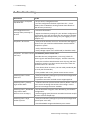
User Guide QL40 ABI – Acoustic Borehole Imager v11.01.10 Advanced Logic Technology sa Mount Sopris Instruments Co., Inc. Bat A, Route de Niederpallen L‐8506 Redange‐sur‐Attert Luxembourg Phone : +352 23 649 289 Fax : +352 23 649 364 Email : [email protected] Web : www.alt.lu 4975 E. 41st Ave. Denver, CO 80216 USA Phone : +1 303 279 3211 Fax : +1 303 279 2730 Email : [email protected] Web : www.mountsopris.com Table of Contents 1 2 3 General Information ........................................................................................................ 1 1.1 Overview .................................................................................................................. 1 1.2 Dimensions............................................................................................................... 2 1.3 Technical Specification............................................................................................. 3 Measurement Principle ................................................................................................... 5 2.1 Reflection coefficient ............................................................................................... 6 2.2 Acoustic head operation .......................................................................................... 6 Notes on QL tool assembly .............................................................................................. 9 3.1 4 Operating Procedure ..................................................................................................... 13 4.1 Preliminary note..................................................................................................... 13 4.2 Quick Start.............................................................................................................. 14 4.3 Tool Communication with ALT Logger ................................................................... 15 4.4 Tool Communication with MATRIX ........................................................................ 15 4.5 Configuring Tool Parameters ................................................................................. 16 4.5.1 Azimuthal Resolution .................................................................................... 16 4.5.2 Open Hole Mode Settings.................................................................................. 17 4.5.3 Cased Hole Mode Settings ............................................................................ 18 4.5.4 Advanced Settings ......................................................................................... 19 4.5.5 Tool Details.................................................................................................... 22 4.6 5 QL40 stack assembly ................................................................................................ 9 Recorded Parameters and Browsers...................................................................... 23 4.6.1 Recorded parameters ........................................................................................ 23 4.6.2 MChNum Browser Window............................................................................... 24 4.6.3 Surface Image Browser Window (AbiSurfaceImg)............................................. 24 4.6.4 Thickness Image Browser Window (AbiThicknessImg)...................................... 24 4.6.5 Caliper Browser Window (AbiCaliper) ............................................................... 24 Performance Check & Calibration .................................................................................. 24 5.1 Mirror rotation....................................................................................................... 24 5.2 Functionality test of the deviation system............................................................. 24 5.2.1 Functionality test ............................................................................................... 24 5.2.2 Rolling test – azimuth and tilt check.................................................................. 24 5.3 Marker Position...................................................................................................... 24 6 Maintenance ................................................................................................................. 24 6.1 Tool Top Adapter ................................................................................................... 24 6.2 Acoustic head......................................................................................................... 24 6.2.1 Cleaning the acoustic head bottom section ...................................................... 24 6.3 Pressure Housing.................................................................................................... 24 6.4 Upgrading QL40 ABI firmware ............................................................................... 24 6.4.1 Checking the communication ............................................................................ 24 6.4.2 Upgrading the firmware .................................................................................... 24 7 Troubleshooting ............................................................................................................ 24 8 Appendix ....................................................................................................................... 24 8.1 Parts list.................................................................................................................. 24 8.1.1 Tool delivery kit QL40‐ABI ................................................................................. 24 8.1.2 Spare kit QL40‐ABI (ref. 2090001001) ............................................................... 24 8.2 Technical drawings................................................................................................. 24 Index ..................................................................................................................................... 24 1 – General Information 1 1 General Information The QL40 ABI is the latest generation of acoustic televiewer. Based on more than 10 years of experience and market leadership with BHTV technology, the new system consists of a completely redesigned acoustic sensor and new electronics. The electronic architecture uses a 14 Bit A/D converter directly coupled to a superfast 75 Mops DSP digital signal processor. The DSP is performing complex data processing operations in real time on each individual ultrasonic wave train and that allows a wider dynamic range of signal detection and easy field operation in a wide variety of logging applications. This QL40 ABI bottom sub has its own Telemetry board, Power supply element and A/D converter allowing the tool to be operated as a stand‐alone probe (QL tool top needed) or in combination with other subs of the QL family. 1.1 Overview Acoustic borehole scanner tools generate an image of the borehole wall by transmitting ultrasound pulses from a fixed transducer with rotating mirror and recording the amplitude ‐ travel time of the signals reflected at the interface between borehole fluid and the formation (borehole wall). Compared to the older FAC40 model which measures a single echo, one amplitude and one travel time, the QL40 ABI has multi‐echo capability. This is achieved by digitally recording the reflected acoustic wave train. On line analysis of the acoustic data is made by the DSP. Sophisticated algorithms allow the system to detect the reflection from the acoustic window and to separate and classify all subsequent echoes. Minimum input from the operator is needed to enable: Automatic or manual adaptation to variable borehole conditions. Improved dynamic range of signal detection. Very high travel time resolution. The implementation of different operating modes. For example, when run inside PVC casing, the tool can record both the echo of the PVC casing and that of the borehole wall. With multi‐echoes processing, application of the tool may be extended to steel casing thickness and corrosion evaluation. Tool upgrades and the implementation of customized operating modes can be done by simply downloading new firmware to the tool from the surface computer. Advanced Logic Technology – www.alt.lu 2 1 – General Information 1.2 Dimensions Figure 1-1 QL40-ABI dimensions Mount Sopris Instruments – www.mountsopris.com 1 – General Information 3 1.3 Technical Specification Tool Diameter: Length: Measurement point: Weight: Max. Temp: Max.Pressure: Cable: Cable type: Digital data transmission: Compatibility: Acoustic sensor: 40mm 1.617m 0.165m (from probe bottom) 6.7 kgs 70°C 200bar Mono, Coaxial, 4 or 7 conductor Up to 500 Kbits per second depending on wireline ALTlogger – ABOX – Matrix Figure 1-2 Acoustic head Acoustic sensor: Measurement range1: Focusing diameter2: Frequency: Acoustic beam width: Rotation speed: Azimuthal resolution: Caliper resolution: Orientation sensor: Sensor: Location: Orientation: Inclination accuracy: Azimuth accuracy: Fixed transducer and rotating focusing mirror 6” – 20” (150mm‐500mm) 6” (152mm) 1.2 Mhz 3 mm Up to 12 revolutions per second ‐ automatic 72, 144, 288 operator defined 0.08mm APS544 Middle point of sensor located at 1.365 m from tool bottom 3 axis magnetometer, 3 accelerometers 0.5 degree 1.2 degree 1 2 Diameter range of the hole in which the measurement is possible. Diameter of the hole where the focusing of the acoustical beam is optimum. Advanced Logic Technology – www.alt.lu 4 1 – General Information Mount Sopris Instruments – www.mountsopris.com 2 – Measurement Principle 5 2 Measurement Principle An understanding of the basic principles of operation of the televiewer is essential for successful use of the tool. The QL40 ABI televiewer produces images of the borehole wall which are based on the amplitude and time of travel of an ultrasonic beam reflected from the formation wall. The ultrasonic energy wave is generated by a specially designed piezoelectric ceramic crystal and has a frequency of around 1.2MHz. On triggering, an acoustic energy wave is emitted by the transducer and travels through the acoustic head and borehole fluid until it reaches the interface between the borehole fluid and the borehole wall. Here a part of the beam energy is reflected back to the sensor, the remainder continuing on into the formation medium at a changed velocity (Figure 2‐1). By careful time sequencing the piezoelectric transducer acts as both transmitter of the ultrasonic pulse and receiver of the reflected wave. The travel time for the energy wave is the period between transmission of the source energy pulse and the return of the reflected wave measured at the point of maximum wave amplitude. The magnitude of the wave energy is measured in dB, a unit less ratio of the detected echo wave amplitude divided by the amplitude of the transmitted wave. Figure 2-1 Wave propagation Advanced Logic Technology – www.alt.lu 6 2 – Measurement Principle 2.1 Reflection coefficient The strength of the reflected signal depends principally on the impedance contrast between the borehole fluid and the formation (Figure 2‐1). The reflection coefficient r is given by the following equation: r = (bvb‐mvm) / ( bvb+mvm) where b = density of formation m = density of borehole fluid vb = velocity of sound of formation vm = velocity of sound of borehole fluid The larger the reflection coefficient is the greater is the signal reflection and thus the ability to detect the signal. From the equation above it may be seen that when the properties of the borehole fluid and borehole wall are similar, i.e. bvb mvm, the reflection coefficient r approaches zero and there is negligible reflection. In this situation determination of the true reflected wave is made more difficult. 2.2 Acoustic head operation The acoustic wave is generated by applying a high voltage pulse across the two faces of a piezo ceramic disc. The applied voltage causes deformation within the crystal structure, either an expansion or contraction depending on the polarity of the applied voltage, with a resultant energy wave emitted normal to the free surface. It has been shown that the beam generated by this process has a maximum energy at a distance of twice the diameter of the disc and that after this point the beam tends to diverge. In order to optimize the beam energy at the point of investigation the ALT televiewer head has been designed as illustrated below (Figure 2‐2). Figure 2-2 Focussing arrangement Mount Sopris Instruments – www.mountsopris.com 2 – Measurement Principle 7 Motor Mirror Acoustic window Transducer Figure 2-3 Abi40 acoustic head architecture The acoustic wave propagates along the axis of the tool body and is then reflected perpendicular to this axis by a special reflector that focuses the beam to a high‐energy point of +/‐ 3 mm diameter. The radial distance of the focal point from the axis of the tool is determined by the focal length of the mirror, +/‐ 75mm (for an acoustic head with a 6” focusing mirror). The frequency of the transmitted wave is determined amongst other factors such as ceramic composition by the diameter of the piezo transducer, a smaller diameter giving a higher frequency. The ALT televiewer operates around 1.2MHz. The reflector is mounted on the drive shaft of a stepper motor. This enables the position of measurement to be rotated through 360°. Sampling rates of 72, 144 and 288 measured points per revolution are available, thus at maximum resolution a near continuous image of the borehole wall is made. The higher sampling rate can be used for better resolution in larger diameter boreholes but is less useful in small diameters due to overlap of the sampling points. Advanced Logic Technology – www.alt.lu 3 – Notes on QL tool assembly 9 3 Notes on QL tool assembly QL stands for Quick Link and describes an innovative connection between logging tools (subs) allowing to build custom tool stacks. QL40 describes a specific family of logging tools. Each sub is equipped with its own Telemetry board, Power supply element and A/D converter allowing an operation as stand‐alone tool or as a stack in combination with other subs of the QL product family. The QL40 probe line deals with two types of subs ‐ Bottom Subs and Mid Subs. Bottom Sub A bottom sub is a tool that must have one or more sensors located at the bottom. It can be operated in combination with other QL subs connected to the top but it is not possible to connect another sub below. When used in stand‐alone mode the bottom sub only needs a QL40 tool top adaptor, which fits the cable head. Mid Sub A mid sub is a tool that can be integrated anywhere within a stack of tools. When used at the bottom of a tool string a QL40 bottom plug must be used to terminate the string. If the mid sub is used as a stand‐alone tool it needs a QL40 bottom plug at the lower end and a QL40 tool top adaptor at the top. 3.1 QL40 stack assembly QL40 tool stacks are terminated by either a QL40 bottom sub or a QL40 bottom plug. At the top of the stack a QL40 tool top is required to connect the tool string to the cable head. Several tool tops are already available, special ones can be made on request. To assemble and disassemble the subs the C‐spanner delivered with the tool must be used (Figure 3‐1). It is recommended that before each assembly the integrity of the O‐rings (AS216 Viton shore 75) is verified. Prime the O‐rings with the silicon grease that was supplied with the subs. C‐spanner O‐rings Figure 3-1 C-spanner and O-rings of QL connection Advanced Logic Technology – www.alt.lu 10 3 – Notes on QL tool assembly The following example of a QL40‐ABI, QL40‐GR and QL40‐GO4 (Figure 3‐2) describes how to replace the QL40‐ABI with a QL40‐Plug in order to run the QL40‐GR sub stand‐alone. QL40‐GO4 tool top QL40‐GR QL40‐ABI Figure 3-2 Tool stack example To remove the QL40‐ABI bottom sub attach the C‐spanner to the thread ring as shown in Figure 3‐3, unscrew the thread ring and remove the QL40‐ABI bottom sub. Thread ring Figure 3-3 Unscrewing the thread ring and removing the bottom sub Mount Sopris Instruments – www.mountsopris.com 3 – Notes on QL tool assembly 11 After checking the O‐ring integrity slip the QL40‐Plug over the exposed QL connector (Figure 3‐4) attach the C‐spanner and screw the thread ring until the plug fits tight. Bottom plug Figure 3-4 Attaching the QL40-Plug The QL40‐GR can now be run stand‐alone (Figure 3‐5). Figure 3-5 QL40-GR mid sub with tool top and bottom plug Advanced Logic Technology – www.alt.lu 12 3 – Notes on QL tool assembly Mount Sopris Instruments – www.mountsopris.com 4 – Operating Procedure 13 4 Operating Procedure 4.1 Preliminary note Acoustic televiewer image quality is highly dependent upon tool centralisation. One set of centralisers is supplied with the QL40 ABI and is suitable for all tools with an external diameter of 40mm. The standard assembly comprises upper and lower mounting rings with sets of 3”, 5” and 6” bowsprings. Two C spanners are provided for tightening the locking ring. Bowsprings for other borehole diameters are available on request. The following points relating to the use of centralisers should be considered: The centralisers should be fitted before mating the tool with the wireline cable head and should always be fitted from the cable head end to avoid damaging the acoustic window. The compression ring of the centraliser, i.e. the one that is screwed tight, should always be fixed toward the top end of the sonde. This is to avoid catching on a downhole obstruction when winching up. Use the C spanner to fasten the fixing rings but take care not to cross thread or over tighten them as this could damage the pressure housing (The weak point of the bowsprings is the welded bearing pin. Take care during assembly as the weld can be broken by reverse bending.) The QL40 ABI enables inspection behind PVC casing. In this situation, the PVC casing must be properly centred in the borehole and the tool correctly centralised in the casing to obtain satisfactory results. Figure 4-1 QL40 ABI with mounted centralizers. Advanced Logic Technology – www.alt.lu 14 4 – Operating Procedure 4.2 Quick Start Note: Parts of the topics discussed in these sections below assume that the user is familiar with the data acquisition software. Refer to the corresponding operator manuals for more details. Information about assembly and configuration of tool stacks can be found in the same manuals. 1. Connect the QL40 ABI to your wireline and start the data acquisition software. 2. Select the relevant QL40 ABI tool from the drop down list (Figure 4‐2) in the software’s Tool panel (if your tool is not listed check that your tool configurations file is stored in the designated folder on your computer). 3. In the Tool panel switch on the tool (click On button) and verify that the power indicator shows a valid (green) level. Figure 4-2 Tool panel The system goes through a short initialization sequence which sets the default parameters and communication settings held in the tool configuration file. The configuration returned by the tool is also checked during this procedure. (Setup tool communication as explained in chapter 4.5 if error message is displayed.) 4. On the Tool panel (Figure 4‐2) click the Settings / Commands button to configure your tool for open hole/cased hole logging (see chapter 4.3 and 4.4 for details). 5. In the Acquisition panel (Figure 4‐3) select the sampling mode (depth or time). Click on Settings and specify the corresponding sampling rate. Switch on the sampling (click the ON button). 6. Press the Record button in the Acquisition panel (Figure 4‐ Figure 4-3 Acquisition panel 3), specify a file name and start the logging. 7. During logging observe the controls in the Telemetry panel: Status must be valid (green light); Bandwidth usage in green range; Memory buffer should be 0%; Number of Data increases and number of Errors Figure 4-4 Telemetry panel negligible. Verify motor status (synchronization) in MChNum browser is valid. 8. To end the logging procedure press the Stop button in the Acquisition panel and turn off the sampling (click OFF button). 9. In the Tool panel power off the tool. Mount Sopris Instruments – www.mountsopris.com 4 – Operating Procedure 15 4.3 Tool Communication with ALT Logger The telemetry provided through the ALTLogger is self‐tuning. In case communication status is not valid the user can manually adjust the settings. In the Telemetry panel of the dashboard click on Settings to display the Configure Tool Telemetry dialog box (Figure 4‐5). A procedure to achieve valid communication is given below: Change the Baudrate to 41666 kbps. Verify that the Downhole Pulse width knob is set on 20 (default value). This value is the preferred one and is suitable for a wide range of wirelines. For long wireline (over 2000m), increasing the pulse width could help to stabilize the communication. The reverse for short wireline (less than 500m). Set the Uphole discriminators in the middle of the range for which the communication status stays valid. Increase the Baudrate, check the communication status stays valid and the Bandwidth usage (in Telemetry panel of the dashboard) is below the critical level. When Uphole discriminators are properly set, store the new configuration as default. The tool should go through the initialisation sequence the next time it is turned on. Figure 4-5 Tool communication settings 4.4 Tool Communication with MATRIX The tool telemetry can be configured through the Telemetry panel of the Matrix dashboard. By clicking on Settings, the operator has access to the Configure ALT Telemetry dialog box (Figure 4‐6) providing various controls to adjust the telemetry settings and monitor its current status. The Analysis View displays the current discriminator levels (vertical yellow lines) and a histogram of the up‐hole data signal. The scales of the Analysis View can be adjusted using the Vertical Scale and Horizontal Scale knobs and the linear / logarithmic scale buttons. The status of the configuration should be flagged as Valid (indicated by the LED being green). In any other case (LED red) the telemetry should be adjusted (we assume a pulse signal is displayed in the analysis view). Click on the Advanced button to display additional controls to tune the telemetry. Advanced Logic Technology – www.alt.lu 16 4 – Operating Procedure The Automatic settings option is the preferred mode and should allow the telemetry to be configured for a wide range of wirelines without operator input. For wirelines with a more limited bandwidth, the operator might need to turn off the automatic mode and adjust the telemetry settings manually. For each wireline configuration, the discriminators (vertical yellow lines) for the positive and negative pulses must be adjusted in order to obtain a valid communication status (see Figure 4‐6) for an example of a suitable discriminator position). There is also the option to alter the baudrate in order to optimize the logging speed. The input gain can be increased (long wirelines) or decreased (short wirelines) in order to set up the discriminator levels correctly. Figure 4-6 Matrix telemetry settings Once the telemetry is correctly set, store the new settings as default. The tool should go through the initialization sequence in “Valid” status the next time the power is turned on. 4.5 Configuring Tool Parameters The Configure ABI Tool Parameters dialog box (Figure 4‐7) can be accessed by clicking on the Settings / Command button on the dashboard’s Tool panel. 4.5.1 Azimuthal Resolution The azimuthal resolution allows the operator to choose the number of points sampled per revolution of the tool sensor. Sampling rates of 72, 144 and 288 measured points per revolution are available. The higher sampling rate can be used for better resolution in larger diameter boreholes but it might be less useful in small diameter hole as it would cause an overlap of sample points. The speed of rotation of the focusing mirror is directly linked to the azimuthal resolution and echo mode chosen. Mount Sopris Instruments – www.mountsopris.com 4 – Operating Procedure 17 Figure 4-7 Tool settings – Open Hole Mode (caliper scale here in µs) 4.5.2 Open Hole Mode Settings This record mode is used in open‐hole conditions or to record the inner face of a casing. Using the Caliper Max controls (Figure 4‐7) the extension of the real time preview of the ultrasonic full waveform can be determined. Adjust the max. caliper settings to allow detection and recording of the main echo in all cases. The caliper limit and full waveform scale can be expressed in µsec, mm or inches. a) b) c) Figure 4-8 (a-c) Acoustic full waveform preview The waveform preview allows the user to adjust the limits of two gates – the Acoustic Window gate and the Echo Gate. The Acoustic Window is represented by a red dashed line while the Echo Gate is shown as gray dashed line (Figure 4‐8 (a‐c)). The tool firmware will record the strongest amplitude in the signal train within the Echo Gate and records Advanced Logic Technology – www.alt.lu 18 4 – Operating Procedure amplitude and taveltime. The Acoustic Gate allows determination of the tool’s acoustic window reflection time. Echo limits can be determined automatically or adjusted interactively in the preview. Square and triangle symbols indicate whether the limits of the gates are automatically set (square or no symbol) or if the user can adjust the limit with the mouse cursor (triangle). To toggle from automatic to manual mode click the Advanced button (see section 4.5.4 Advanced Settings). The Wave Azimuth knob in the full waveform preview box (Figure 4‐7) gives the possibility to display the ultrasonic wave train in a preferential direction other than the reference position of the mirror. 4.5.3 Cased Hole Mode Settings This acquisition mode is used to perform casing thickness measurements and corrosion evaluation in steel casings. Figure 4-9 Tool settings dialog box – Cased Hole Mode The operator will need to select from the dropdown casing list the nominal specifications of the casing under investigation (Figure 4‐9). Casing external diameter and weight can be displayed in metric or imperial units. A mix of units is possible. The position of the External diameter and Thickness knobs will be adjusted automatically according to the casing selected from the drop down list. When selecting Custom from the casing list, the operator has the option to enter external diameter and thickness settings manually. The two Range values displayed next to the thickness knob are the measurement limits within which the system will compute the casing thickness. In addition to the Echo and Acoustic Window Gates a third gate, the Thickness Echo Gate (green dashed line), is available for which only the end limit is user adjustable. Reduction of the gate length may be necessary if the ringing signal from the casing is superimposed by noise (e.g. multiples of the inner reflection) towards the end of the gate period. Mount Sopris Instruments – www.mountsopris.com 4 – Operating Procedure 19 4.5.4 Advanced Settings By clicking on Advanced in the Tool Parameters dialog box (Figure 4‐7or Figure 4‐9) the operator has access to additional settings listed below: Caliper settings (Figure 4‐10) The parameters shown in this dialog box are used to compute caliper values from recorded traveltime. Tool diameter (mm): Default tool acoustic window diameter (read only). Blanking zone (µs): Default blanked zone set before starting the detection of the acoustic window reflection (read only). Nominal window time (µs): Default blanked zone set after the detection of the max amplitude and travel time of the acoustic window reflection. The system will look for the next useful echo (i.e. borehole wall, casing inner surface) after this nominal window (read only). Fluid velocity (m/s): Fluid velocity constant used to convert the acoustic travel time from µsec to metric or imperial units. This value can be edited. Figure 4-10 Advanced settings – Caliper Echo Gate settings (Figure 4‐11) Select from the Start Mode and Length Mode drop down lists, to choose whether the Echo Gate limits (Figure 4‐8 (a‐c)) are controlled by the user or set automatically. If Manual has been selected triangular handles are displayed in the preview window which can be dragged with the mouse. It is also possible to edit the gate limits by turning the controls in this dialog box. Figure 4-11 Advanced settings – Echo Gate Advanced Logic Technology – www.alt.lu 20 4 – Operating Procedure Three modes are supported to set the Start time of the Echo Gate: Automatic: The system will automatically detect and record the highest amplitude occurring after the Acoustic Window Gate and the upper limit of the Echo Gate (Figure 4‐8 b). Automatic is the recommended setting. Automatic Multiple: The system will automatically adjust the start time of the Echo Gate so that the first multiple of the Acoustic Window reflection is skipped. This setting is useful for large diameter boreholes when the amplitude of the first multiple of the Acoustic Window reflection is higher and arrives earlier than the echo from the borehole wall. Manual: Manual adjustment of the Echo Gate start time is useful to exclude noise with amplitudes higher than the formation signal (e.g. exclude the reflection from the inside of a PVC casing). Manual adjustment of the Echo Gate Length could be useful when noise with large amplitudes arrives towards the end of the gate period (e.g. exclude Acoustic Window reflection multiples when logging in soft formations). Acoustic Window Gate settings (Figure 4‐12) The length of the acoustic window can be adjusted by the user dragging the triangular handle in the preview or turning the knob in this dialog box Figure 4-12 Advanced settings – Acoustic Window (Automatic mode) The system will automatically pick the arrival time of the most dominant amplitude within the Acoustic Window Gate and will store the values in the WinTime channel. Thickness settings (Figure 4‐13) The parameters shown in this dialog box are used to compute thickness values from recorded traveltime. Tool diameter (mm): Default tool acoustic window diameter (read only). Fluid velocity (m/s): Fluid velocity constant used to convert the acoustic travel time from µsec to metric or imperial units. This value can be edited. Casing velocity (m/s): Steel velocity constant used to convert the acoustic travel time from µsec to metric or imperial units. This value can be edited. Mount Sopris Instruments – www.mountsopris.com 4 – Operating Procedure 21 Figure 4-13 Advanced settings – Acoustic Window (Thickness) The length of the Thickness Echo Gate can be adjusted by dragging the triangular control in the preview or by turning the knob in this dialog box. Options settings For diagnostic purposes the full waveform signal shown in the preview window can be recorded. As this will affect the performance of the system we do not recommend turning the recording option on during normal logging operation. Figure 4-14 Advanced settings – Options Advanced Logic Technology – www.alt.lu 22 4 – Operating Procedure 4.5.5 Tool Details Note: All information displayed in the following dialog box is read only and not editable. By clicking on the Tool Details button in the Configure ABI Tool Parameters dialog box three tabs (Figure 4‐15) become available summarizing serial numbers, acoustic details and firmware version of the tool. If necessary, newer tool firmware versions can be uploaded. The upgrade procedure will be explained in a later chapter. Figure 4-15 Tool details dialog box Mount Sopris Instruments – www.mountsopris.com 4 – Operating Procedure 23 4.6 Recorded Parameters and Browsers 4.6.1 Recorded parameters The following data channels will be recorded by the tool: TravelTime (1st echo): Two Way Traveltime 1st echo ‐ µsec st Amplitude (1 echo): Amplitude 1st echo (NM = North Magnetic, HS = High Side) TravelTime (2nd echo): Two Way Traveltime 2nd echo ‐ µsec nd Amplitude (2 echo): Amplitude 2nd echo (NM = North Magnetic, HS = High Side) ThicknessTTime: Two Way Traveltime within casing ‐ µsec Score: Quality Index for thickness signal detection Azimuth: Azimuth from Magnetic North – deg Tilt: Inclination from verticality – deg RBR: Orientation angle to High Side – deg Roll: Tool relative bearing calculated from accelerometers ‐ deg Mroll: Tool relative bearing calculated from magnetometers ‐ deg Magn.Field: Magnetic field surrounding the borehole ‐ µT Gravity: Absolute value of the Earth gravity – g WndTime: Two way traveltime of acoustic window reflection – µsec WndAmpl: Amplitude of acoustic window reflection VT CPU: Sensor reading for CPU board temp. ‐ volt T CPU: Temperature recorded on CPU board ‐ °C T APS: Temperature inside the deviation sensor ‐ °C MotSpeed: Motor ‐ Speed of rotation – rps Motor Status: Diagnostic code Motor Period: Time for a single revolution – sec Advanced Logic Technology – www.alt.lu 24 4 – Operating Procedure 4.6.2 MChNum Browser Window Figure 4‐16 shows a typical example of the numerical values displayed in the MChNum browser window during logging. Figure 4-16 Multi Channel Browser for Numerical Data (MChNum) Motor: Status Azimuth: Tilt: Roll: Mroll: Magn.Field: Gravity: Win.Time: Motor synchronisation status Tool record status Azimuth from Magnetic North ‐ deg Inclination from verticality ‐ deg Tool relative bearing calculated from accelerometers ‐ deg Tool relative bearing calculated from magnetometers ‐ deg Magnetic field surrounding the borehole ‐ µT Absolute value of the earth gravity ‐ G Travel time of the acoustical window ‐ µs 4.6.3 Surface Image Browser Window (AbiSurfaceImg) The system returns an unwrapped image of the borehole wall based on the caliper and amplitude of the recorded acoustic signal (Figure 4‐17). The left column shows the caliper image and the right column the amplitude image. These images consist of a succession of variable density colors. By double clicking on the log titles Minimum and Maximum scale values may be adjusted to enhance areas of interest. Mount Sopris Instruments – www.mountsopris.com 4 – Operating Procedure 25 Figure 4-17 QL40 ABI Surface Image browser window Note that the displayed units for the caliper log can be converted to either metric or imperial units via the menu bar’s Settings option or by double clicking on the log title. Image orientation: Image is non‐oriented Orient image to magnetic North Orient image to High Side of the tool There are two modes of tool data orientation: orientation to High Side and orientation to North. Orientation to High Side is used in inclined boreholes when magnetic data is unavailable (for example in a cased hole). Figure 4-18 Orientation to Magnetic North Advanced Logic Technology – www.alt.lu 26 4 – Operating Procedure Vertical scales and grids: Depth mode display and pre‐defined depth scales Operator defined depth scales, interval spacings and settings Time mode display Vertical grid settings Horizontal grid settings 4.6.4 Thickness Image Browser Window (AbiThicknessImg) In Cased Hole Mode, the ABI Thickness browser displays on the left column an unwrapped color coded image of the casing thickness processed by the system (Figure 4‐19). The right column is a color‐coded image of the score. The score is a quality index on the thickness measurement. In a general way, high score values mean high reliability of the thickness measurement and the reverse. Figure 4-19 QL40 ABI Thickness Image As for the Surface image browser, scales and units of the displayed parameters can be adjusted by double clicking on the log title or from the Settings option of the menu bar. 4.6.5 Caliper Browser Window (AbiCaliper) Caliper browser ‐ Open Hole Mode The open hole caliper view (Figure 4‐20) shows in real‐time a cross‐section of the acoustic caliper. Scaling, concentric gridding and displayed units are adjustable from the tool bar “Settings” option. Mount Sopris Instruments – www.mountsopris.com 4 – Operating Procedure 27 The black circle shows the external limit of the acoustic window. The red circle is the cross section of the acoustic caliper corresponding to the main reflector detected by the system (borehole wall or inner surface of a casing) As for the image browsers, the caliper view can be oriented to Magnetic North, High side or displayed without orientation. During the acquisition, it is possible to centralize the caliper cross section to remove the effect of decentralization of the tool in the borehole. Clicking the symbol can do this. Statistical caliper figures (Min, Max, Average) are displayed on the left side of the dialog box. Figure 4-20 QL40 ABI Caliper – Open Hole Mode Caliper browser ‐ Cased Hole Mode Cross sections of both of the inner (red circle) and outer (orange circle) surface of the casing are shown in this browser (Figure 4‐21), giving a good visualization of the casing thickness in real‐time. The space between the 2 circles is filled with the corresponding color coded score values. Orientation, scaling, concentric gridding and displayed units are adjustable from the menu bar’s Settings option. Figure 4-21 QL40 ABI Caliper – Cased Hole Mode Advanced Logic Technology – www.alt.lu 28 5 – Performance Check & Calibration 5 Performance Check & Calibration 5.1 Mirror rotation Direction of motor rotation is clockwise viewed from top of tool (Figure 5‐1): Placing 2 fingers3 on the acoustic window may check mirror rotation. In time mode, record the 2 finger traces shown4 on the Abi surface browser. Remove your right finger from the acoustic window; the corresponding right finger trace on the Abi surface image should disappear. Figure 5-1 Direction of mirror rotation 5.2 Functionality test of the deviation system 5.2.1 Functionality test The QL40 ABI‘s deviation system is factory calibrated and does not require further calibration. The functionality tests subsequently described have to be done to check that the tool is giving the correct deviation outputs: To verify inclination at 0° and 90°, position the probe vertical (acoustic head pointing down) for 0° inclination and horizontal for 90° inclination. Note that uphole measurement is possible with the APS544 deviation system as it includes 3 accelerometers. In uphole, the inclination will be between 90° and 180° (probe vertical, acoustic head pointing up). To verify azimuth accuracy, a good compass and an area free of magnetic materials must be used. Use a compass to orient North with the probe horizontal and verify that the azimuth reading is 0° ± 1°. Repeat the procedure for East, South and West directions. 5.2.2 Rolling test – azimuth and tilt check Azimuth and tilt could be tested by rotating the tool about its long axis while maintaining both a constant inclination to the vertical, say 15°, and a fixed azimuth. The data imported into WellCAD should show a deviation of the azimuth less than the limit of ±2.5° and a deviation of the tilt less than the limit ±0.5°. 3 4 Wet your fingers first for a better coupling Adjust the amplitude scale to enhance the finger traces Mount Sopris Instruments – www.mountsopris.com 5 – Performance Check & Calibration 29 5.3 Marker Position The marker position is the angular value between the reference Y deviation axis, and the first trace recorded by the tool. The acoustic head contains a coil sensor that detects a passing magnet for each rotation of the mirror drive. The synchronization pulse generated by this allows the tool micro‐ controller to monitor rotation speed against number of samples and determine whether or not the acquired data is valid. The sensor is physically positioned during assembly to be close to either 0° or 180° from the measuring zero point, the +Y axis. However, it is necessary to verify exactly this position and record it in the *.sub file of the acoustic head to obtain the correct orientation of data. This procedure must be redone if maintenance operations have been made on the acoustic head. A reference mark is engraved on both ends of the tool pressure housing to indicate the direction of the +Y axis (Figure 5‐2). Reference mark Acoustical head Figure 5-2 Pressure housing – reference mark Figure 5-3 Marker jigs To check the marker position two support jigs are needed, one square and one a half square in section as shown in Figure 5‐3. Each of the jigs must have a 40mm diameter hole centered on the intersection of the vertical and horizontal centre axis. The square section jig must have a square pin mounted on it with one edge of the pin at a radius of 28mm from the hole centre, and on the vertical axis of the hole when the jig is placed on edge. This jig also needs a locking screw to clamp the jig to the tool body. Slide this jig over the bellows cover of the Advanced Logic Technology – www.alt.lu 30 5 – Performance Check & Calibration acoustic head until the pin is positioned above the plastic window. The second jig is used to support the other end of the tool. With the tool on a flat, exactly horizontal surface held in the two support jigs and the logging software with the Mchnum browser running, rotate the tool until the Roll display shows 90°. (Figure 5‐4). Figure 5-4 Mchnum browser – Roll 90° The jig holding the pin must then be locked in position with the screw – without damaging the head! Remove or lock the second support jig and suspend the tool vertically in a bucket of water (Figure 5‐5). Figure 5-5 Tool vertically suspended Adjust the window settings so that the pin is visible, normally default values will do but be careful that your image is not a window reflection. Right Edge Figure 5-6 Travel time and amplitude images Mount Sopris Instruments – www.mountsopris.com 5 – Performance Check & Calibration 31 Record a file in time mode. Leave the tool suspended for a later verification. Import the data file into WellCAD selecting no orientation when prompted in the Import options dialog box. Use the Tabular Editor and look for the angular position of the edge of the pin’s reflection (alternatively select the log title and move your cursor over the data observing the amplitude and azimuth values displayed in the lower left edge of the WellCAD window). Be sure that it is the right side of the pin in relation to mirror rotation! Both the Travel Time and the Amplitude images can be used to determine the correct angle. Use the new value and update the MarkerPos parameter in the *.sub file of the acoustic head. Having completed the calibration, verify the new settings by orienting the tool using a compass such that the marker jig pin is approximately aligned to North. With orientation to North selected in the ABI40Img browser , i.e. North at the left of the plot, you should find that the edge of the pin is now close to the extreme left hand edge of the plot with the bulk of the pin showing on the extreme right. If so you have correctly set the value. If the pin is in the middle of the plot you are 180° out. Advanced Logic Technology – www.alt.lu 32 6 – Maintenance 6 Maintenance Warning: Removing the electronic chassis from pressure housing without prior consultation with ALT will void the tool warranty. The QL40 ABI televiewer is a delicate instrument and should be treated with care at all times. Excessive shock or extreme temperatures should be avoided and the tool should always be transported in its transport case or a similarly cushioned enclosure. Never support the tool on the acoustic head. Experience shows that with attention to these points the QL40 ABI will give several years fault free operation. The QL40 ABI televiewer separates into four basic parts The tool top adaptor The pressure housing The electronic chassis The acoustic head. Tool top adaptor Pressure housing Electronic chassis Acoustical head Figure 6-1 QL40-ABI and QL40-GO4, exploded view Should it become necessary to open the tool, the tool parts must be separated in the following sequence: 1. Remove the tool top adapter 2. Remove the acoustic head 3. Remove the pressure housing Disassembly of the electronic chassis from the pressure housing should never be attempted in the field. Mount Sopris Instruments – www.mountsopris.com 6 ‐Maintenance 33 6.1 Tool Top Adapter The tool top adapter provides the connection between wireline cable head and chassis electronics and can be provided to suit 7 conductors, 4 conductors, mono or special wireline configurations. The adapter is fixed by the means of a threaded ring screwed in the pressure housing. To remove the tool top adapter, use the correct C spanners provided with the tool ‐ see picture below (Figure 6‐2). Figure 6-2 Removing the tool top The wireline cable head socket and tool top adapter connector pins should be checked for cleanliness before each use of the tool. The pin inserts, whether 4 or 7 pin, have a locating mark indicating WL1 or A that should line up with the slot mating with the cable head. Check O‐Ring seals and apply silicon grease before re‐assembly. Silicon grease of a similar type to RS Components Ref 494‐124 is suitable for this and other O‐Ring seals. (Rem: O‐Ring reference for tool top and for the quick link 40 is AS215 26,57 x 3,53 Viton Shore 75) Figure 6-3 QL40-GO4 Tool top adaptor Advanced Logic Technology – www.alt.lu 34 6 – Maintenance Figure 6-4 QL40-GO7 tool top adaptor Figure 6-5 QL40-GO1 tool top adaptor Mount Sopris Instruments – www.mountsopris.com 6 ‐Maintenance 35 6.2 Acoustic head Warning: The televiewer acoustic head is extremely delicate and must be treated gently at all times. Any laterally applied force on the end of the head is liable to cause damage! The acoustic head is attached to the electronic chassis of the sonde by three 2.5mm hex set screws. To remove the entire televiewer head the tool top and pressure housing must first be removed as described below. Slacken off the fixing screws and slide the televiewer head off the connector. The connector has a keyway to locate the head with the correct orientation. Plastic window Bellow and its protection cap (semitransparent) Figure 6-6 Acoustical head Re‐assembly is the same procedure in reverse order, but taking care not to force the head on to the connector. This will result in bent or broken connector pins! Check all “O” ring seals (Orings AS215, 26.57x3.53, viton, shore 75) and apply silicon grease to them. The acoustic head needs to be properly maintained to give the best image results. Note the following points: Check that there are no air bubbles visible in the acoustic window. Air can separate out of the oil filling the head, notably after airfreight at low pressure, and can also work its way out of the inner parts of the motor. The presence of air in the head is indicated by a spotty image or streaking. These effects may come and go as the orientation of the tool is changed. Check that there is not excessive lateral movement on the end of the head. The bellows cap must be screwed up against the acoustic window but not excessively tight. If the acoustic signal is lost, check for isolation between pins A&B in the acoustic head. The most common reason for loss of signal is the cutting of the signal coax to the transducer in the head. This happens when the window is rotated relative to the head body. Check with a gentle twisting motion that the window does not rotate more than a degree or two relative to the tool body. Advanced Logic Technology – www.alt.lu 36 6 – Maintenance At very low temperatures the oil in the acoustic head becomes viscous and this may prevent the mirror from rotating. In this case keep the tool and head warm before use. 6.2.1 Cleaning the acoustic head bottom section The bottom section of the televiewer assembly houses a pressure compensating bellows that must be free to move. For this reason the bellows cover is removable to allow cleaning of the exterior of the bellows. The interior of the bellows and main body of the televiewer head is oil filled. Both, the end of the bellows cover and its side wall, have holes to allow pressure equalization, and these holes must be kept clear. The bellows cover is threaded at the top end and held by a screw thread on the main body below the nylon window. The cover should only be hand tightened. Keep the bellows section clean. This will prevent the deterioration of glue seals and the bellows itself. Grit lodged in the folds of the bellows can cause perforation if left over a period of time. When removing the cover, it is important to hold the nylon mirror section only, which is locked integrally with the main tool, while unscrewing the cover. Wrenches must NOT be used (Figure 6‐7 and Figure 6‐8). Warning: Any Rotation of the nylon section relative to the main tool pressure housing will result in damage to the head and probable tool failure. (The outer casing to the motor section of the televiewer head, i.e. between the nylon and main pressure housing, is free to rotate on “O” ring seals and is not locked with the nylon mirror window section.) The necessity for cleaning will depend on the borehole fluid and borehole conditions. The bellows should only be cleaned when the sonde was used in heavily contaminated fluids, i.e. heavy muds or sediments, or when the fluid is known to be corrosive. In this case it is important to clean deposits off the bellows where it is glued to the flanges at either end. The bellows wall is thin and can become perforated if allowed to corrode. Figure 6-7 Unscrewing the bellows cover Mount Sopris Instruments – www.mountsopris.com 6 ‐Maintenance 37 Figure 6-8 Bellows cover removed 6.3 Pressure Housing The main pressure housing is locked on to the televiewer head by four 2.5mm hex cap screws. After removal of the tool top, the pressure housing can be removed after undoing these screws. When separating the two parts, place the tool on suitable stands, grip the pressure housing with one hand and the acoustic head close to the joint with the other and apply a straight pull. During re‐assembly extreme care should be taken not to over tighten the fixing screws which may shear off if overloaded! The outside of the pressure housing is marked with a Y symbol to indicate the position of the Y axis vertical and upward. The purpose of this is to simplify tool checking. When re‐assembling the pressure housing make sure that the reference mark is correctly aligned with the upper side of the deviation sensor. 6.4 Upgrading QL40 ABI firmware In accordance with the ALT policy of continuous development the QL40 ABI has been designed to allow firmware upgrades. The current version of firmware installed in a tool may be verified in the Tool Details window opened from the Tool Settings dialogue box. Firmware upgrade procedure is as follows: 1. Checking the communication is valid. 2. Upgrading firmware 6.4.1 Checking the communication 1. Connect the QL40 ABI tool to your acquisition system. 2. Start ALTLog/Matrix software. 3. In the Tool panel select the appropriate tool and turn on the power. 4. In the Communication panel, select Settings. Check baud rate is set to 41666 and communication status is valid (Figure 6‐9 or Figure 6‐10). Advanced Logic Technology – www.alt.lu 38 6 – Maintenance Figure 6-9 Tool communication settings - ALTLog Figure 6-10 Tool communication settings - Matrix Warning: Telemetry must be tuned properly. Bad communication may abort the upgrade of the firmware! 6.4.2 Upgrading the firmware In the Tool panel, select Tool settings/commands. Check that the communication status is valid (Figure 6‐11). Figure 6-11 Tool settings dialog box Mount Sopris Instruments – www.mountsopris.com 6 ‐Maintenance 39 1. Click on Tool Details. Note that the firmware version currently in use is displayed in the firmware box. Click on the Upgrade button (Figure 6‐12). Figure 6-12 Tool Details dialog box 2. The following message will appear (Figure 6‐13). Click Yes to validate your choice. Figure 6-13 Warning Message during firmware upload 3. Select and open the appropriate .hex file provided (Figure 6‐14). The upgrade will start. Figure 6-14 Select firmware upgrade 4. During the upgrade procedure, the following message is displayed: Figure 6-15 Firmware upgrade progress window Advanced Logic Technology – www.alt.lu 40 6 – Maintenance 5. Once the upgrade has been successfully completed (Figure 6‐16), click on OK to turn off the tool. Figure 6-16 Successful upgrade 6. Power on the tool to start the upgraded firmware. Check in Tool settings/commands and Tool details that the firmware version has been changed with the new one. Note that this error message (Figure 6‐17) will appear at end of the procedure when the tool firmware upgrade has failed or has been aborted. Check tool communication settings. Figure 6-17 Error message Mount Sopris Instruments – www.mountsopris.com 7 ‐ Troubleshooting 41 7 Troubleshooting Observation To Do Tool not listed in Tool panel drop down list. ‐ Do you have a configuration file? Tool configuration error message when powering on the tool. Tool panel ‐ No current. ‐ Has the configuration file been copied into the …/Tools folder (refer to MATRIX or ALTLog manual about details of the directory structure)? ‐ Check all connections. ‐ Adjust the telemetry settings for your wireline configuration (see chapter 4.3 or 4.4) and store the new settings as default. Apply the appropriate tool settings for your logging run (see chapter 4.5). ‐ Verify that the wireline armour is connected to the logging system. Test your interface cable between winch and data acquisition system. ‐ Verify cable head integrity. ‐ Verify voltage output at the cable head (it should be 120V). Tool panel ‐ Too much current ! Immediately switch off the tool ! (red area). ‐Possible shortcut (voltage down, current up): Check for water ingress and cable head integrity ‐ wireline continuity. ‐ Verify the interface cable between winch slip ring and data acquisition system is not loose at the connectors. Check for possible source of a shortcut. ‐ If the above shows no issues, use test cable provided by ALT to verify tool functionality. ‐ If the problem still occurs, please contact service centre. Telemetry panel ‐ status shows red. ‐ Verify the telemetry settings for your wireline configuration (see chapter 4.3 or 4.4). ‐ If problem cannot be resolved contact [email protected] . Telemetry panel ‐ memory buffer shows 100%. ‐ Indicates that the systems internal memory buffer is full. PC can’t receive incoming data streams fast enough. Ensure your PC has enough resources available. Telemetry panel – bandwidth ‐ Set the baudrate to highest value allowed by your wireline usage shows 100%. configuration. (Overrun error message.) ‐ Reduce logging speed, decrease azimuthal resolution and/or increase vertical sample step. Telemetry panel ‐ large number of errors. ‐ Verify the telemetry settings for your wireline configuration (see chapter 4.3 or 4.4). ‐ Check bandwidth usage and telemetry error status. Advanced Logic Technology – www.alt.lu 42 7 ‐ Troubleshooting Observation To Do Permanent No Sync message ! Immediately switch off the tool ! and red led status in ‐ Stepper motor and mirror synchronization issue. Contact MChNum browser. ALT for Acoustic Head service. Motor stalled and increase of current drawn by the tool. Mount Sopris Instruments – www.mountsopris.com 8 – Appendix 43 8 Appendix 8.1 Parts list 8.1.1 Tool delivery kit QL40-ABI Item No. Qty Part No. Description 1 2 211‐004 C‐spanner 40‐42 (QL43) 2 2 211‐005 C‐spanner 58‐62 (centralizer) 3 1 ALT11235 ABI40 Marker position jig 4 1 ALT11232 ABI40 tool support 5 1 ALT11234 Maker jig pin 6 2 Din934‐M3 Nut M3 7 1 210‐002 Silicon grease 8 1 211‐001 Allen key set 9 1 2090001001 QL40‐ABI ‐ spares kit 8.1.2 Spare kit QL40-ABI (ref. 2090001001) Item No. Qty Part No. Description 1 5 25340642 O Ring Viton shore 75°, 26,57x3,53 ref . : 10023313 2 2 25340668 O Ring Viton shore 75°, 31,42x2,62 ref . : 10023279 3 2 25340667 O Ring Viton shore 75°, 26,65x2,62 ref . : 10023276 4 4 25332006 M4x6mm Hex cap screw A2 DIN7854 5 4 25332757 M2,5x3mm Hex cap scew A2 DIN912 6 3 25331781 M3x6mm Hex skt set screw A2 DIN913 8.2 Technical drawings The following technical drawings are available on request: 19” Rack connection diagram. ABI40 Wiring Diagram. Advanced Logic Technology – www.alt.lu 44 Index Index AbiCaliper, 26 AbiSurfaceImg, 24 AbiThicknessImg, 26 Acoustic head, 35 Acoustic head operation, 6 Acoustic Window Gate settings, 20 Advanced Settings, 19 ALT Logger, 15 Amplitude, 23 Azimuth, 23 Azimuth accuracy, 3 Azimuthal Resolution, 16 Baudrate, 15 bottom sub, 9 Caliper Browser Window, 26 Caliper settings, 19 Cased Hole Mode Settings, 18 Cleaning the acoustic head bottom section, 36 Configuring Tool Parameters, 16 Diameter, 3 Dimensions, 2 discriminators, 15 Downhole Pulse width, 15 Echo Gate settings, 19 External diameter, 18 firmware, 37 Functionality test, 28 General Information, 1 Gravity, 23 head, 6 impedance, 6 Inclination accuracy, 3 Length, 3 Magn.Field, 23 Maintenance, 32 Marker Position, 29 MATRIX, 15 Max. Temp, 3 Max.Pressure, 3 MChNum Browser Window, 24 Measurement Principle, 5 mid sub, 9 Mirror rotation, 28 Motor Period, 23 Motor Status, 23 MotSpeed, 23 Mroll, 23 Open Hole Mode Settings, 17 Mount Sopris Instruments – www.mountsopris.com Index 45 Operating Procedure, 13 Options settings, 21 Overview, 1 Parts list, 43 Performance Check & Calibration, 28 Pressure Housing, 37 QL, 9 QL tool, 9 Quick Start, 14 RBR, 23 Recorded Parameters and Browsers, 23 Reflection coefficient, 6 Roll, 23 Rolling test, 28 Score, 23 stack assembly, 9 Surface Image Browser Window, 24 T APS, 23 T CPU, 23 Technical drawings, 43 Technical Specification, 3 Telemetry, 15 Thickness, 18 Thickness Image Browser Window, 26 Thickness settings, 20 ThicknessTTime, 23 Tilt, 23 Tool Communication with ALT Logger, 15 Tool Communication with MATRIX, 15 Tool Details, 22 Tool Head Adapter, 33 TravelTime, 23 Trouble Shooting, 41 Upgrading ABI40 firmware, 37 VT CPU, 23 Weight, 3 WndAmpl, 23 WndTime, 23 Advanced Logic Technology – www.alt.lu