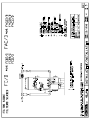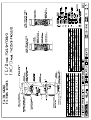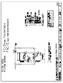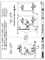
1
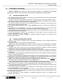
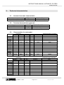
AUTOMATIC FILTERS WITH DIFFERENTIAL PRESSURE CONTROL SERIE : FC/D-DP FAC/D-DP FC/D-DP-DUAL FAC/D-DP-DUAL INSTRUCTIONS MANUAL WARNING! The equipment must be used only for the utilization for which they have been designed, as shown in the technical documentation. Read carefully this leaflet until the end before starting any operation. Proceed strictly according to all directions included in this manual. Automatic filters series FC/D and FAC/D are designed to treat raw water supplied from municipalities or from well. ANY OTHER APPLICATIONS OF THE EQUIPMENT DIFFERENT THAN THE MENTIONED ONES IS MADE UNDER THE ONLY RESPONSIBILITY OF THE USER. For any assistance concerning the installations, maintenance or utilization of the equipment apply the NOBEL Service Center closest to you or directly : NOBEL S.r.l. via Monfalcone 8 – I-20132 Milano tel. +39 02 2827968 fax +39 02 2610839 rev. 2 Page 1 of 21 fcd-dp_mi-r2.doc INSTRUCTIONS MANUAL AUTOMATIC FILTERS FC/D-DP -FAC/D-DP INDEX 1.Safety .........................................................................................................................................................3 1.1.General.................................................................................................................................................3 1.2.How to displace the unit .......................................................................................................................3 1.3.Hydraulics ............................................................................................................................................3 1.4.Electrical...............................................................................................................................................3 1.5.How to store and delivery.....................................................................................................................3 2.Principles of working ..................................................................................................................................4 2.1.Quartz-sand filters FC/D ......................................................................................................................4 2.2.Activated-carbon filters FAC/D.............................................................................................................4 3.Technical characteristics ............................................................................................................................5 3.1.Assumed raw water characteristics .....................................................................................................5 3.2.Technical characteristics (general) ......................................................................................................5 3.3.Characteristics for each model ............................................................................................................5 3.4.Dimensions ..........................................................................................................................................6 3.5.Weights ................................................................................................................................................6 4.Installation ..................................................................................................................................................7 4.1.How to remove packaging ...................................................................................................................7 4.2.How to move and lift the unit................................................................................................................7 4.3.Placing & commissioning .....................................................................................................................7 4.4.Hydraulic connections ..........................................................................................................................8 4.5.How to load the media filter..................................................................................................................9 4.6.Electrical wiring connections................................................................................................................9 5.End cycle and regeneration......................................................................................................................10 5.1.End cycle............................................................................................................................................10 5.2.Regeneration......................................................................................................................................10 5.3.Inhibit of the regeneration ..................................................................................................................11 CONTROL PANEL ......................................................................................................................................12 6.1.Functions of the logical programmer..................................................................................................12 6.2.Signals on the display of the programmer .........................................................................................13 6.3.How to use the buttons function of the programmer..........................................................................13 7.SETTINGS................................................................................................................................................14 7.1.How to set current time and day of the week.....................................................................................14 7.2.How to set day and time of regeneration ...........................................................................................14 7.3.How to set time of phases, delay, pressure drop value .....................................................................15 7.4.Factory set..........................................................................................................................................16 8.Starting-up ................................................................................................................................................17 9.SERVICE & MAINTENANCE ...................................................................................................................18 9.1.Media filter, nozzles ...........................................................................................................................18 9.2.Disposal..............................................................................................................................................19 10. MAIN COMPONENTS...........................................................................................................................19 11. TROUBLE-SHOOTING GUIDE ............................................................................................................20 Annex • DRAWING 1: dimensions • DRAWING 2: components models FC05/D÷FC11/D, FAC05/D÷ FAC11/D • DRAWING 3: components models FC15/D÷FC80/D, FAC15/D÷FAC60/D • DRAWING 4: installation models FC05/D÷FC11/D, FAC05/D÷ FAC11/D • DRAWING 5: installation models FC15/D÷FC80/D, FAC15/D÷FAC60/D • DRAWING transducers installation • WIRING DIAGRAM • running test certificate • solenoid valves manual • diaphragm valves manual s.r.l.Milano - ITALY Page 2 of 20 fcd-dp_mi-r2.doc – r.2 INSTRUCTIONS MANUAL AUTOMATIC FILTERS FC/D-DP -FAC/D-DP 1. Safety 1.1. General The equipment has been designed and constructed according to D.P.R. n° 459 of 24th July 1996 (regulation for accomplishment of Norms 98/37/CEE, 91/368/CEE, 93/44/CEE and 93/68/CEE regarding the unification of States members laws in so far as machines are concerned). It has been designed and constructed according to European Norms UNI EN 292-1, UNI EN 292-2, UNI EN 292-2/A1, UNI EN 983, CEI EN 60439-1, CEI EN 60 204-1. Only authorized and skilled personnel will be allowed to carry out installation, start up as well as routine and planned maintenance. 1.2. How to displace the unit Particular care and attention should be put in during moving and displacing of heavy items, in order to avoid injuries to persons or damage (see § 3.5 pag. 6). The heavy parts must be lifted and displaced always hooking and lifting them by the points shown on the drawings (see fig. 1) and using only suitable ropes, hooks and/or chains, according to the weight (see weight table). 1.3. Hydraulics All operations must be performed by and/or under direct supervision of skilled and authorized operators, using proper tools and personal protection devices if required (CE marked). Before any operation of taking out pipes or part of hydraulic system, it is required to release the pressure inside and empty the part of the system. 1.4. Electrical Before starting any operation on electrical devices, be sure that main power supply is OFF. All operations must be performed by skilled and authorized operators. In case of liquid leakage, switch off the main power supply before operate. Before the switching ON, be sure all the parts of the system are perfectly dry. Check that the available electrical power is correct before connection. Do not make preliminary wiring connections. 1.5. How to store and delivery t = ºC • • • • 5÷45 5÷45 5÷45 5÷45 closed rooms open space transport installation t = ºF humidity rel. 41÷113 5÷95% without condensate 41÷113 5÷95% without condensate 41÷113 5÷95% without condensate 41÷113 5÷95% without condensate notes protect from sun-light and rain. protect from sun-light and rain. protect from sun-light and rain. s.r.l.Milano - ITALY Page 3 of 21 fcd-dp_mi-r2.doc – r.2 INSTRUCTIONS MANUAL AUTOMATIC FILTERS FC/D-DP -FAC/D-DP 2. Principles of working FC/D and FAC/D series filters are used for water treatment for residential and industrial applications as well. All the materials are food grade and approved for drinking water. 2.1. Quartz-sand filters FC/D The filtration through a sand media is a mechanical process that allows to remove suspended solids (even of small dimensions) from water. The slower is the linear flow (speed of water trough the filtering bed), the better is the filtration action. During the process, as the filtering bed traps the suspended particles, as filtration action increases, since the trapped solids works the same way of a filtering bed! But it also increases the resistance of the filtering bed against the water flow; so the pressure drop between inlet and outlet increases as well. The maximum allowed pressure drop is 1 bar (100 kPa), after that it is required to backwash the filtering bed. The purpose of the backwashing is to re-built the filtering bed efficiency, by removing the solids trapped during service; it is featured by a counter-flow of water through the filtering bed. The programmer allows to set the regeneration according to the max allowable pressure drop across the filter and/or at pre-set time and days. For the best working of the filter, the backwashing must be featured before the pressure drop reaches the threshold level (1 bar - 100 kPa). During regeneration the water supplying is completely inhibited by means of a membrane valve mounted on the outlet line. 2.2. Activated-carbon filters FAC/D Filtration through a bed of activated carbon is the process that allows to remove organic matters and chlorine from water. The lower is the flow rate, the better is the filtration action. FAC/D series filters are designed and sized for chlorine removal. The expected life of activatedcarbon used as de-chlorination (chlorine removal) is very long; it works as chemical reduction of chlorine to chloride ion. Activated carbon action is not selective in removing the substances contained in water and crossing the filtering bed: hence, it removes also the organics the water contains, if any. Therefore, it could happen that the filtering bed is exhausted or clogged by the trapping of substances contained in water, even if the purpose of treatment was not the removal of these substances, but just the de-chlorination. Furthermore, it could happen that the filtering bed releases some of the substances previously trapped in higher concentration than before. Since it is quite impossible to forecast the exhaustion of the activated carbon bed, or to monitor the exhaustion itself, with current instrumentation, the utilization of an activated carbon filter must be strictly avoided without adequate pre-treatments, like quartz-sand filtration, chlorination, etc. Whether raw water contains organics and/or is biologically polluted, FAC/D series filters CANNOT be used without written authorization by NOBEL Technical Department. The activated-carbon bed also works as a mechanic filter same way of quartz-sand bed. Although this working should be avoided, it can happen that the pressure drop of activated-carbon bed reaches a value of 1 bar (100 kPa); in this case the backwashing of the filtering bed is required. The programmer allows to set the regeneration according to the max allowable pressure drop across the filter and/or at pre-set time and days. For the best working of the filter, the backwashing must be featured before the pressure drop reaches the threshold level (1 bar - 100 kPa). It is recommended to run the regeneration only when it is strictly required: the backwashing causes the mixing of the bed and could displace the higher layers of activated carbon (most polluted) from the top to the bottom of the column. During regeneration the water supplying is completely inhibited by means of a membrane valve mounted on the outlet line. s.r.l.Milano - ITALY Page 4 of 21 fcd-dp_mi-r2.doc – r.2 INSTRUCTIONS MANUAL AUTOMATIC FILTERS FC/D-DP -FAC/D-DP 3. Technical characteristics 3.1. Assumed raw water characteristics • water temperature (min÷max) • water pressure (min÷max) 3.2. connections 110÷240 1/50÷60 30 20÷30 0.2÷1.0 (20÷100) backwashing water consumption flow m³/h IN/OUT drain operating 1¼" 1½" 1½" 2" 2" 2½" DN80 DN80 DN80 DN100 DN100 DN100 DN100 1" 1¼" 1¼" 1½" 1½" 2" 2½" 2½" 2½" DN80 DN80 DN80 DN80 3.2 4.0 5.7 7.8 10.0 13.0 16.0 20.0 23.0 27.0 31.0 35.0 40.0 connections MODEL FAC05/D FAC08/D FAC11/D FAC15/D FAC20/D FAC25/D FAC30/D FAC40/D FAC50/D FAC60/D V ph/Hz W min. bar (kPa) Characteristics for each model MODEL FC05/D FC08/D FC11/D FC15/D FC20/D FC25/D FC30/D FC40/D FC45/D FC50/D FC60/D FC70/D FC80/D 5÷40 (41÷104) 1.5÷8.0 (150÷800) Technical characteristics (general) • power supply • regeneration time • ∆p min/max 3.3. ºC (ºF) bar (kPa) max backwash liters 6.5 8.0 11.0 15.0 20.0 26.0 32.0 40.0 46.0 53.0 62.0 70.0 80.0 4.8 6.0 8.5 11.0 15.0 20.0 24.0 30.0 35.0 40.0 46.0 53.0 60.0 1600 2000 2850 3900 5000 6500 8000 10000 11500 13500 15500 17500 20000 flow m³/h backwashing water consumption IN/OUT drain max backwash liters 1¼" 1½" 1½" 2" 2½" 2½" DN80 DN80 DN100 DN100 1" 1¼" 1¼" 1½" 2" 2" 2½" 2½" DN80 DN80 5.0 8.0 11.0 15.0 20.0 24.0 30.0 40.0 48.0 61.0 3.0 4.8 6.6 9.0 12.0 14.4 18.0 24.0 28.8 36.6 500 800 1100 1500 2000 2400 3000 4000 4800 6100 s.r.l.Milano - ITALY Page 5 of 21 fcd-dp_mi-r2.doc – r.2 INSTRUCTIONS MANUAL AUTOMATIC FILTERS FC/D-DP -FAC/D-DP 3.4. Dimensions See DRAWING 1 dimensions 3.5. Weights WEIGHT MODEL FC05/D FC08/D FC11/D FC15/D FC20/D FC25/D FC30/D FC40/D FC45/D FC50/D FC60/D FC70/D FC80/D vessel quartz-sand kg kg 04÷07 mm 1÷2 mm 2÷3 mm anthracyte l (kg) shipping approx. kg on service approx. kg 135 150 180 300 340 390 435 550 610 670 740 870 1100 100 120 200 250 300 400 500 600 700 800 900 1100 1250 50 60 80 100 150 200 200 300 350 400 450 500 600 35 50 50 100 100 150 200 200 250 300 350 400 450 40(28) 50(35) 70(49) 100(70) 130(91) 150(105) 200(140) 250(175) 300(210) 350(245) 400(280) 450(315) 500(350) 380 460 600 900 1050 1350 1600 2000 2300 2600 2900 3400 4000 600 700 1000 1400 170 2100 2600 3100 3600 4200 4800 5500 6400 WEIGHT MODEL vessel kg FAC05/D FAC08/D FAC11/D FAC15/D FAC20/D FAC25/D FAC30/D FAC40/D FAC50/D FAC60/D 150 180 300 340 390 435 550 670 740 1100 quartz-sand shipping on service kg activated carbon l (kg) approx. kg approx. kg 30 50 50 75 100 100 150 200 250 300 200(96) 280(134) 350(168) 500(240) 650(312) 800(463) 1000(480) 1350(648) 1600(768) 2000(960) 300 400 560 700 900 1000 1300 1700 2000 2600 500 700 900 1300 1600 1900 2400 3200 3700 4800 1÷2 mm s.r.l.Milano - ITALY Page 6 of 21 fcd-dp_mi-r2.doc – r.2 INSTRUCTIONS MANUAL AUTOMATIC FILTERS FC/D-DP -FAC/D-DP 4. Installation 4.1. How to remove packaging The vessels are shipped wrapped in a plastic foil; remove it with care before starting-up. Keep the cards and everything contained inside the packaging. The media filter are shipped as separated: • in bags of 25 kg (35 liters approx) each or fraction anthracite • in bags of 25 kg each or fraction quartz sand • in bags of 25 kg (50 liters approx) each or fraction activated carbon 4.2. How to move and lift the unit The vessels can be displaced when they are empty, hooking and lifting by the special rings mounted on the upper part of the vessels (see fig. 1). It is recommended to use proper sized hooks and ropes, according to the weight. It is also possible to hook and lift the vessel by the bearing legs. GOLFARI HOOKING CAUTION : DO NOT LIFT OR MOVE THE UNIT HOOKING OR CATCHING BY THE PRE-ASSEMBLED PARTS. GAMBE DI SOSTEGNO LEGS 4.3. Placing & commissioning Place the unit according to the available room of the site and the required room for current maintenance and service of the equipment. See the dimensional drawing. • Place the column of media filter on a perfectly flat surface. See the dimensional drawing concerning the placing of the unit according to the walls of the site and required room for maintenance and service. The shown scheme is only suggested; the column can be placed in different positions; according to the inlet/outlet connections on the valve groups. • Fix the valves manifold to the vessel (see installation drawing) • Fix the control board to the valves manifold DUAL arrangement only : • Repeat the same operations for both columns; yet, the control panel is only one for both columns and must be fixed on column A (see installation drawing). s.r.l.Milano - ITALY Page 7 of 21 fcd-dp_mi-r2.doc – r.2 INSTRUCTIONS MANUAL AUTOMATIC FILTERS FC/D-DP -FAC/D-DP 4.4. Hydraulic connections (see DRAWINGS installation and components) In order to avoid shut-off during maintenance operations, an emergency by-pass line should be provided • Complete the line from inlet fittings to the raw water line. • Complete the line from outlet fittings (valve V2) to the treated water line. • Connect the drain valves (V1 and V5) to a floor drain. The gate valve mounted downstream of the valve V5 will be used to adjust the backwash flow rate. A common flexible pipe made in plastic or rubber can be used for the drain line; its diameter must be of at least one size larger of the one mentioned on “CHARACTERISTICS FOR EACH MODEL” table. It is suggested the drain line could be inspected in order to check quantity and quality of drain water, as well as any leakage of media filter from the unit. • Connect the inlet air fitting, placed on the base manifold of the solenoid valves, to a compressed air-mains, complete with pressure reducer, dehumidifier filter and shut-off valve. The air pressure must be kept at value equal or higher of the pressure of water to be treated, with max value of 8.0 bar. • Whether water is used to pilot the valves, the inlet fitting of the base manifold of the solenoid valves must be connected to the pilot water fitting (¼"), pre-arranged on the inlet manifold of the column; run to the drain a pipe from the drain fitting (¼") of the base manifold of the solenoid valves. • Complete the line between the outlet fitting of each solenoid valve to the correspondent membrane valve: SOLENOID VALVE Solenoid TYPE v. no. 1 NC 2 NC 3 NC MEMBRANE VALVES no. TYPE V1 V2 V3-V4-V5 NC NA NC-NA-NC All the solenoid valves can be hand-driven by the lever placed at the base of each of them; the turning of the lever simulate the action of the coil. Then, for valves NC type, the valve is closed when the lever is on parallel to the base; it is opened when the lever is on perpendicular to the base itself. DUAL arrangement only : • the hydraulic connections must be made for both columns • each group of pilot solenoid valves (E1A-E2A-E3A / E1B-E2B-E3B) is coupled to its own filtering columns (A/B) • put in the 2 pressure sensors on the inlet and outlet manifolds of the 2 columns (see transducers drawing) s.r.l.Milano - ITALY Page 8 of 21 fcd-dp_mi-r2.doc – r.2 INSTRUCTIONS MANUAL AUTOMATIC FILTERS FC/D-DP -FAC/D-DP 4.5. How to load the media filter The media filter must be loaded inside the vessel afterthat the placing of the filter is completed or in the case the media have to be replaced. • Open both the side man-holes • Check that the filter nozzles are correctly fixed and not damaged. • Load the supplied quartz-sand (2-3 mm size for FC/D filters, 1-2 mm size for FAC/D filters) into the vessel, through the lower man-hole, until the sand covers completely the filternozzles. Make a flat surface of the sand using a wooden tool, in order to avoid any damage to the coating of the vessel. • Close the man-hole, after checking the integrity and correct position of the gasket, by tightening the nuts. • Load the rest of supplied media filter into the vessel, through the upper man-hole (or through the upper head, see components drawing). The media filter are shipped separately; check that the shipped and available quantity complies exactly with the quantity listed in the Weight Table (see § 3.5 pag. 6). Filtering media must be loaded, one after the other one, and according to the following order: ◊ quartz sand 2÷3 mm (only for filters FC) ◊ quartz sand 1÷2 mm ◊ quartz sand 0.4÷0.7 mm (only for filters FC) ◊ anthracite (only for filters FC) ◊ activated carbon (only for filters FAC) Take care to make a flat surface of each layer of sand, before load the next one. • After completed the loading, close the upper man-hole (or upper head), after checking the integrity and correct position of the gasket, by tightening the nuts 4.6. Electrical wiring connections Make the electrical wiring connections inside the control panel, as below explained (see also WIRING DIAGRAM). o o o o o o o o + 6 + 7 o o o o o o o o Power supply 110÷240V, 50÷60 Hz directly to the clamps of the main switch GND pressure inlet trasducer P-IN " " " " " " pressure outlet trasducer P-OUT " " " " " " A free voltage contact for remote segnalation of running regeneration (max 1 A, max 24 V) is also available, directly on the output Q4 of the programmer. DUAL arrangement only : the free voltage contact of output Q4 of the programmer reports the running regeneration of column A, while the running regeneration of column B is reported by free voltage contact of output Q4 of expansion card It is also possible to inhibit the starting of regeneration by mean of a free voltage external contact. It will be connected to one of any clamp + and the input I2 of the programmer. s.r.l.Milano - ITALY Page 9 of 21 fcd-dp_mi-r2.doc – r.2 INSTRUCTIONS MANUAL AUTOMATIC FILTERS FC/D-DP -FAC/D-DP 5. End cycle and regeneration 5.1. End cycle The unit is equipped with 2 pressure sensors plumbed on inlet and outlet line of the filters; the sensors gauge the correspondent pressure (IN/OUT) and therefore also the differential pressure; when the pressure drop across the filtering bed reaches the value of 0.8 bar (80 kPa), the end-cycle is driven. During normal service, possible peaks of pressure could cause a wrong indication of reached max allowable pressure drop; in order to avoid that, the end-cycle driving is delayed of an adjustable time. Hence the max pressure drop must remain for all the time of adjusted delay, to drive the end-cycle. The electronic micro-processor programmer allows also to run the regeneration according to time schedule, at pre-set time and day (max 3 regeneration per day). To set the regeneration by time only (regardless of pressure drop), proceed as follows : - set at least 1 regeneration by time schedule - enter as max allowable pressure drop (end-cycle) the value 10000. To set the regeneration by pressure drop only (regardless of time), proceed as follows : - delete any programmed regeneration by time control - enter as max allowable pressure drop (end-cycle) the desired value (standard =80) 5.2. Regeneration The regeneration is automatically controlled by the electronic programmer according to time schedule or pressure drop. The regeneration can also be started manually at any time, out of any automatic programme, by keeping pushed for 3 consecutive seconds the button function of the programmer. For the correct use of the buttons function of the programmer, proceed as follows (see also the chapter “How to use the buttons function of the programmer”): • push several times the button until ESC+C… appears on the display • push and keep pushed the button ESC and immediately afterthat the desired button funtion (), keeping both pushed for 3 consecutive seconds. • by pushing the button ESC without pushing the button functions within 2 seconds, the display skips visualization to menu; release and then push again the button ESC to go back to visualization ESC+C… • The pushing of manual start of the regeneration, while the regeneration is already running, has not any effect. • An undesirable regeneration can be interrupted, in any moment, by keeping pushed the button RESET for 3 consecutive seconds. Warning : When the manually started regeneration is completed, the unit will continue to work according to previous programming. DUAL arrangement only : Regeneration can also be started manually for each column independent way : press and keep pressed for 3 consecutive seconds the function button of the programmer, the regeneration of column A is started; while pressing and keeping pressed for 3 consecutive seconds the function button of the programmer, the regeneration of column B is started. s.r.l.Milano - ITALY Page 10 of 21 fcd-dp_mi-r2.doc – r.2 INSTRUCTIONS MANUAL AUTOMATIC FILTERS FC/D-DP -FAC/D-DP The regeneration can also run in case of power failure, by hand-driving the lever of the pilot solenoid valves: the solenoid valve is closed when the lever is on parallel to the base and it is open when it is on perpendicular to the base itself. Naturally, the compressed air supplying (air controlled valves) or pilot water supplying (water controlled valves) must be assured. The correspondent membrane valves (controlled by the pilot solenoid ones), if NC type is open when the solenoid valve is open, and viceversa if the membrane valve is NO type. PHASE SERVICE BACKWASHING RINSE SOLENOID VALVES EXCITED (=OPEN) // E2 - E3 E1 - E2 OPEN VALVES V2 - V4 V3 - V5 V1 - V4 The regeneration phases run one after another, as follows : 1. Backwash : during this phase, the water flushes from the bottom to the top of the column, lifting the filtering media and releasing the solids trapped on its surface during the service. The backwashing water flows to drain from the top of the column. This is the only phase, during which the water crosses through the column from the bottom to the top. 2. Rinse : it is the phase during which the filtering media are rinsed; at the end of this phase the column is ready to start again a new service cycle. NOTE: During regeneration the water supplying is completely inhibited. NOTE : For DUAL arrangement, when regeneration is required, column A starts it immediately, while in the same time column B enters in “regeneration required”state, although it continues to feed water. At the end of regeneration of column A, with an adjustable delay (see following how to adjust time of delay), column B starts regeneration. 5.3. Inhibit of the regeneration It is possibile to inhibit the automatic starting of regeneration by mean of an external contact, using the input I2 of the programmer as described at paragraph "Electrical wiring connection". Hence, when the end-cycle is reached, the filter will remain on REGENERATION REQUIRED until the inhibit signal is switched off. Even if the inhibit signal is still on, it is also possible to start manually the regeneration, as above explained. s.r.l.Milano - ITALY Page 11 of 21 fcd-dp_mi-r2.doc – r.2 INSTRUCTIONS MANUAL AUTOMATIC FILTERS FC/D-DP -FAC/D-DP 6. CONTROL PANEL 6.1. Functions of the logical programmer The logical programmer Siemens serie LOGO handles the logical working of the whole unit. Its display allow the visualization of the status of the logical inputs (marked as I), the logical outputs (marked as Q), current time and date, the several messages enabled by the programme. It is also possible to modify the settings of the entered numerical parameters (marked as B). The numbering of the inputs and outputs is arranged on several rows, each of them correspond to a ten (I1÷I9, I10÷I19 ecc.). By pushing the buttons or the display shows, alternatively, the visualizations of the service : current time and date, inputs, outputs, (M, to be ignored), function buttons (ESC+C..). By pushing the buttons and the messages enabled by the programme are visualized. The used functions are the following : MARK I2 I3 I7 (AI1) I8 (AI2) Q1 Q2 Q3 Q4 Q5 Q6 Q7 Q8 B1 B2 B3-1 B4 B5 B6 DESCRIPTION input available for regeneration inhibit button RESET pressure sensor INLET (P-IN) pressure sensor OUTLET (P-OUT) output of the solenoid valve E1 (E1A for DUAL arrangement) output of the solenoid valve E2 (E2A for DUAL arrangement) output of the solenoid valve E3 (E3A for DUAL arrangement) output of running regeneration (column A for DUAL arrangement) output related to solenoid valve E1B (for DUAL arrangement only) output related to solenoid valve E2B (for DUAL arrangement only) output related to solenoid valve E3B (for DUAL arrangement only) output related to report of running regeneration column B (for DUAL arrangement only) time of BACKWASHING time of RINSING setting time and days of regeneration delay of driving of end-cycle max allowable pressure drop time of delay starting regeneration of column B after conclusion of regeneration column A (for DUAL arrangement only) All settings of automatic working are factory-made at the shipment. See the chapter “SETTINGS” to check the factory-set. s.r.l.Milano - ITALY Page 12 of 21 fcd-dp_mi-r2.doc – r.2 INSTRUCTIONS MANUAL AUTOMATIC FILTERS FC/D-DP -FAC/D-DP 6.2. Signals on the display of the programmer The report messages enabled by the programmer are visualized on the display one at a time, with a determinate priority. The buttons and are used to scroll the messages. The button is used to turn back to service visualizations. The messages that can be visualized are : "P IN" "P OUT" "DP" "SET" "BACKWASH" "RINSE" "WAITING FOR REGENERATION" "RIGENERATION BACKWASH FILTER A" "…… B" "RIGENERATION RINSE FILTER A" "…… B" 6.3. These visualizations are always available. They show, respectively, (values are expressed in bar) : current inlet pressure current outlet pressure current differential pressure value max differential pressure value to drive end-cycle This visualization is available only when the filter is running the backwash phase. The pre-set time and the elapsed time from the starting of the phase are also shown. This visualization is available only when the filter is running the rinse phase. The pre-set time and the elapsed time from the starting of the phase are also shown. This visualization appears only when the filter reaches the endcycle, but the regeneration cannot run due to the inhibit signal (input I2). For DUAL arrangement, the visualization is available for each column This visualization is available for DUAL arrangement only. The signal indicates which column in on backwashing This visualization is available for DUAL arrangement only. The signal indicates which column in on rinse How to use the buttons function of the programmer The 4 buttons can have special functions whether enabled by the software. For their utilization, proceed as follows : • push several times the button until the display shows ESC+C… • push and keep pushed the button ESC and immediately afterthat the desired button function () • by pushing the button ESC without pushing the button functions within 2 seconds, the display skips visualization to menu; release and then push again the button ESC to go back to visualization ESC+C… Warning : s.r.l.Milano - ITALY Page 13 of 21 fcd-dp_mi-r2.doc – r.2 INSTRUCTIONS MANUAL AUTOMATIC FILTERS FC/D-DP -FAC/D-DP SETTINGS 7.1. How to set current time and day of the week The programmer is equipped with internal clock, keeping exact time for 80 hours in case of power failure. To set the current time and day, proceed as follows : 1. 2. 3. 4. 5. 6. 7. push the button ESC push the button until the pointer > indicates "Set …" push the button OK the pointer indicates “Clock..”, push the button OK the pointer indicates “Set Clock..”, push the button OK push the button to point the day or the number to be modified when the pointer blinks on the day or the number to be modified, push the buttonor until the new desired day or value is shown (symbols related to days of week are explained at following chapter) 8. repeat the same operation with other values, if required 9. push the button OK to confirm (save) the modifications 10.push twice the button ESC to go back to the visualization of service. The programmer is already factory set for automatic updating with european summer time (S/W Time ON = EU) 7.2. How to set day and time of regeneration M/- T/- W/- T/- F/- S/- S/- Tuesday Wednesday Thursday Friday Saturday Sunday The days of the week can be set one by one; they appear on the display in the weekly row: it is possible to select (visualized the initial letter of the day) or not (visualized the symbol -). The row and explanation of the symbols that appear on the display are : Monday 7. The available digits to set the time are between 00:00 and 23:59; the symbol --:-- indicate not any ON and/or not any OFF. The regeneration starts at the time set on the line ON. The time on the line OFF MUST BE NECESSARILY SET one minute later than the time on the line ON. The programmer allows to set up to 3 regeneration per day (B3-1, B3-2, B3-3). s.r.l.Milano - ITALY Page 14 of 21 fcd-dp_mi-r2.doc – r.2 INSTRUCTIONS MANUAL AUTOMATIC FILTERS FC/D-DP -FAC/D-DP Proceed as follows to modify : 1. 2. 3. 4. 5. 6. 7. 8. 9. 10. 11. 12. 13. push the button ESC push several times the button until the pointer > points "set param" push the button OK . push several times the button until the display shows the parameter where to make the modification (B3 - 1 or other) push the button OK , the blinking cursor will take place on the line of the days (D) by pushing the button the cursor moves on the positions correspondent to the days of the week push the button to enable/disable by pushing the button the cursor moves on the several digits of the hours (lines ON and OFF) when the cursor blinks on the digit to modify, push several times the until the desired number appears repeat the same operations with other digits, whether required. push the button OK to confirm the modifications push the button to visualize other parameters which must be modified, and operate as explained at above points 5 ÷11, or push the button ESC to leave the modification menu push the button ESC to go back to visualization of service. 7.3. How to set time of phases, delay, pressure drop value Proceed as follows to modify : 1. 2. 3. 4. 5. 6. 7. 8. 9. 10. 11. push the button ESC push several times the button until the pointed > points "set param" push the button OK . push several times the button until the parameter to modify is shown (B1 or other) push the button OK . by pushing the button , move the cursor on the digit to modify when the cursor blinks on the digit to modify, push the button until thge desired digit appears repeat the same operations with other digits, whether required push the button OK to confirm the modifications proceed as explained for other modifications of other parameter or push the ESC per to leave the modification menu push the button ESC to go back to visualization of service NOTE: • during the modifications, the normal service is NOT interrupted. • In modification menù, ref. to the timers, the digits visualized on the line (marked as Ta) underneath the line of the time setting (marked as T), indicate the status of the present counting of the time related to the selected timer s = seconds (00,00 ÷ 99,95) • time basis are : m = minutes (00:00 ÷ 99m:59s) h = hours (00:00 ÷ 99h:59m) • although the programmer allows to set values up to 19999, in the field of the max allowable pressure drop (B5), let us remind that the real max allowable value is 100, correspondent to a pressure drop of 1 bar (=100 kPa = max allowable value pressure drop across the filter). s.r.l.Milano - ITALY Page 15 of 21 fcd-dp_mi-r2.doc – r.2 INSTRUCTIONS MANUAL AUTOMATIC FILTERS FC/D-DP -FAC/D-DP 7.4. Factory set Parameter B1 B2 B4 B5-ON B5-OFF B6 Parameter utilization time BACKWASH time RINSE delay of the max differential pressure driving max differential pressure Must be necessarly the same of B5-ON time of delay starting regeneration of column B after conclusion of regeneration column A (for DUAL arrangement only) utilization Start of regeneration by time " " B3 - 1 B3 - 2 B3 - 3 Day of regeneration M - set value 15.00 m 05.00 m 60.00 s 80 (equal to 0.8 bar) 80 10.00 s time ON time OFF 00 : 01 -- : --- : -- 00 : 02 -- : --- : -- s.r.l.Milano - ITALY Page 16 of 21 fcd-dp_mi-r2.doc – r.2 INSTRUCTIONS MANUAL AUTOMATIC FILTERS FC/D-DP -FAC/D-DP 8. Starting-up The starting-up of the unit consists of running a first regeneration cycle, during which the filtering media column will be filled of water, all automatic features will be checked and the unit will be prepared to start the service. At the beginning, it is suggested to operate manually, and to hand-driven the valves, by hand-driving the lever of the pilot solenoid valves: the solenoid valve is closed when the lever is on parallel to the base and it is open when it is on perpendicular to the base itself. This way will allow to stop, to run for longer time or to repeat each phase as desired, and to adjust the flow rates according to the attached table. To start-up the unit, proceed as follows (for DUAL arrangement, operate on column A only): • • • • • • • • • • • DISCONNECT ELECTRIC POWER shut off the inlet, outlet and by-pass gate valves. close quite completely the gate valve along the backwash drain line hand-drive the solenoid valves E3 to open the backwashing membrane valves open slowly and only partially the gate valve on inlet line. The water will enter inside the vessel from the bottom and, during filling, will expel the air inside it. when only water will come out from the drain, open completely the inlet gate valve and adjust the backwash drain gate valve in order that the flow rate will be the highest allowable without any leakage of media filter through the drain line; when the proper flow rate of backwash has been stated, adjust the gate valve definitely. The backwashing phase must run until all the water coming out the drain is perfectly clear. Hand-drive the solenoid valves E3 to close the backwashing membrane valves. Hand-drive the solenoid valve E1 to open the membrane valve V1 (RINSE); the rinse phase must run until all the water coming out the drain is perfectly clear. Hand-drive the solenoid valves E1 to close the valve V1 and to conclude the regeneration. Switch ON the control panel. Open the outlet valve . Starting now the unit is on service and feeds treated water. For DUAL arrangement : repeat all listed operation on column B It is suggested to check, during the running of the first automatic regenerations, that the adjusted flow rates and times are correct. s.r.l.Milano - ITALY Page 17 of 21 fcd-dp_mi-r2.doc – r.2 INSTRUCTIONS MANUAL AUTOMATIC FILTERS FC/D-DP -FAC/D-DP 9. SERVICE & MAINTENANCE Normally, these units do not require any regular maintenance operation and there is not any consumption material to be currently replaced. The only parts that can be aged are the electrical components and moving parts, as listed : • the membrane of the automatic valves; after years, they can be aged and crack. • the solenoid valves can break down (electric) or can get dirty if the pilot fluid is not perfectly clean. • The average life of the media filter is approx 5÷8 years, according to the chemical-phisical characteristics of the water and how often the regeneration is featured. The correct handling of the equipment requires : • check monthly the values of pressure and flow rate of water, which have to comply with stated ones. • check that the air and/or water pressure are within the stated values. • check that the values of pressure shown by the programmer meet the ones gauged by the manometers. Not any further special maintenance operations are required. Not any consumption material is required . 9.1. Media filter, nozzles Whether the filtering bed is clogged and “packed” in order that it is impossible to backwash it properly, the replacing of the media filter is required. Proceed as follows for the emptying : • • • • • • • • • • Switch OFF the control panel Close the shut-off valves upstream and downstream of . Empty the column of water, by opening the bottom drain valve Open the upper-side man-hole (or upper head) Open the lower-side man-hole, leaving one nut inserted in. It will allow to control the flow of the media filter outside. Then open completely the lower and side man-hole. Keep the nuts and gaskets of the man-holes. Flush water to take out the media filter still laying along the internal walls of the column and on the internal nozzles. Complete the emptying of the column, using an aspirator, if necessary. During the last part of the operation, take care not to damage the nozzles mounted on the holding plate. Replace the damaged nozzles, if any. Proceed as explained at § 4.5 to load the new media filter. Proceed as explained at § 8 to start-up the unit, after replacing of media filter. s.r.l.Milano - ITALY Page 18 of 21 fcd-dp_mi-r2.doc – r.2 INSTRUCTIONS MANUAL AUTOMATIC FILTERS FC/D-DP -FAC/D-DP 9.2. Disposal In case of disposal of the unit or parts of it, it must be made according to local laws concerning the waste of the materials. Concerning media filter, they are natural products that, at origin state, can be disposed of as natural products. Whether the activated carbon had trapped special and particular substances, the carbon will be classified as same class of the trapped substances. 10. MAIN COMPONENTS Quantity DESCRIPTION 1 (2) coated steel vessel (see table DIMENSIONS) 1 (2) internal distribution system (see next table) # (x2) media filter (see table WEIGHTS) 5 (10) diaphragm valves in cast-iron (see next table) 3 (6) pilot solenoid valves type 6012-24Vcc/MAN/PA 1 (1) control panel NOBEL made 2 (2) pressure transducers stainless steel, range 0÷10 bar, output 0-10 V, connection ¼" # galvanized steel piping/fittings, several diameters The quantities indicates between brackets () are the ones related to DUAL arrangement. MODEL FC05/D FC08/D FC11/D FC15/D FC20/D FC25/D FC30/D FC40/D FC45/D FC50/D FC60/D FC70/D FC80/D V1 1"NC 1"NC 1"NC 1"NC 1"NC 1"NC 1¼"NC 1¼"NC 1¼"NC 1½"NC 1½"NC 1½"NC 1½"NC diaphragm valves V2 V3 V4 1¼"NO 1"NC 1¼"NO 1½"NO 1¼"NC 1½"NO 1½"NO 1¼"NC 1½"NO 2"NO 1½"NC 2"NO 2"NO 1½"NC 2"NO 2½"NO 2"NC 2½"NO DN80NO 2½"NC DN80NO DN80NO 2½"NC DN80NO DN80NO 2½"NC DN80NO DN100NO DN80NC DN100NO DN100NO DN80NC DN100NO DN100NO DN80NC DN100NO DN100NO DN80NC DN100NO distributor V5 1"NC 1¼"NC 1¼"NC 1½"NC 1½"NC 2"NC 2½"NC 2½"NC 2½"NC DN80NC DN80NC DN80NC DN80NC diaphragm valves MODELLO FAC05/D FAC08/D FAC11/D FAC15/D FAC20/D FAC25/D FAC30/D FAC40/D FAC50/D FAC60/D number/type 12 short 12 short 18 short 30 plate 36 plate 42 plate 56 plate 68 plate 84 plate 87 plate 104 plate 118 plate 142 plate distributor V1 V2 V3 V4 V5 number/type 1"NC 1"NC 1"NC 1"NC 1"NC 1"NC 1¼"NC 1¼"NC 1½"NC 1½"NC 1¼"NO 1½"NO 1½"NO 2"NO 2½"NO 2½"NO DN80NO DN80NO DN100NO DN100NO 1"NC 1¼"NC 1¼"NC 1½"NC 2"NC 2"NC 2½"NC 2½"NC DN80NC DN80NC 1¼"NO 1½"NO 1½"NO 2"NO 2½"NO 2½"NO DN80NO DN80NO DN100NO DN100NO 1"NC 1¼"NC 1¼"NC 1½"NC 2"NC 2"NC 2½"NC 2½"NC DN80NC DN80NC 12 short 18 short 30 plate 36 plate 42 plate 56 plate 68 plate 87 plate 104 plate 142 plate s.r.l.Milano - ITALY Page 19 of 20 fcd-dp_mi-r2.doc – r.2 INSTRUCTIONS MANUAL AUTOMATIC FILTERS FC/D-DP -FAC/D-DP 11. TROUBLE-SHOOTING GUIDE PROBLEM CAUSE • electrical power is • The electronic disconnected programmer does not switch ON • the programmer is defected • The regeneration does not • electrical power is disconnected run • the programmer is not correctly adjusted • the programmer is defected • there is not supplying of pilot • Regeneration is fluid (air or water) electrically started but it does not run hydraulically • one or more solenoid valves are defected • one among (or both) • There is a leakage of membrane valves no. 1 and 5 water to drain during does not close properly. service HOW TO SOLVE • connect electrical power • replace the programmer • connect electrical power • adjust correctly the programmer • replace the programmer • connect properly the supplying of pilot water or compressed air • replace the defected solenoid valves • check the proper working of the pilot solenoid valves • check and clean the seat of the plate of the membrane valve • the membrane valve no. 2 does • check the proper working of the pilot solenoid valve not open • replace the nozzle • one nozzle of distribution system is damaged or broken • The unit does not feed water • There is a leakage of filtering media to the drain or to the outlet line • the manometers are not quite • The values of pressure calibrated shown on the display of the programmer are by far different than the ones • the pressure transducers are gauged by manometers not quite calibrated i sensori di pressione sono starati • check the real pressure values by using a standard instrument; then replace the instrument (manometer or transducer) which gauge the uncorrect value * * Normally, a difference of approx 3 % between the values gauged by the two different measurement systems is acceptable. s.r.l.Milano - ITALY Page 20 of 20 fcd-dp_mi-r2.doc – r.2