1
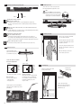
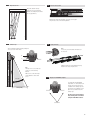
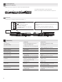
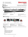
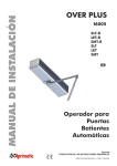
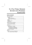
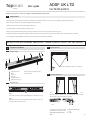
,
User s guide
Topscan
presence
ADSF UK LTD
Tel: 08700 434512
Active infrared presence sensor for swinging, revolving & folding automatic doors
1
Safety instructions
* The device must only be operated at a protective low voltage with safe electrical insulation. Product repairs must be performed solely by the manufacturer.
* Shut off all power going to the sensor before attempting any wiring procedures.
* Maintain a clean & safe environment when working in public areas.
* Constantly be aware of pedestrian traffic around the door area.
* Always stop pedestrian traffic through the doorway when performing tests that may result in unexpected reactions by the door.
* Always check placement of all wiring and components before powering up to ensure that moving door parts will not catch any wires and cause damage to equipment.
* Ensure compliance with all applicable safety standards (i.e. ANSI A156.10) upon completion of installation.
DO NOT LEAVE ANY PROBLEMS UNRESOLVED - NEVER SACRIFICE SAFETY FOR ANY REASON
Preparation / Installation
2
2.3
Mounting the housing
Opening the housing
2.1
3
5
6
2
5
1
3
4
Mounting the aluminium housing on a swinging door.
6
1
2
3
4
5
6
2.2
Aluminum extrusion
Sensor
End cap 2 x
Front cover
Mounting brackets 2 x
Phillips head screws 2 x
Remove end covers by removing screws.
Remove front cover.
2.4
Selecting the detection area
Removing the sensor
left
Option 1
Release the red screws on both mounting brackets, then slide them to the side.
right
Depending on the door opening, a right or left sensing field should be selected.
Factory setting is right sensing field [most common].
Option 2
Release the red screws, then slide the bracket holders together with the sensor
carefully out of the aluminium housing.
Front
To change the sensing field type, slide
the plastic block to position L or R. It
can be found on the back of side the
optics.
Back
Position of the detection area
L = Left
R = Right
1
2.5
Selecting the switching and operating modes
2.7
Mounting the sensor
Mount the sensor in the housing and slide
both mounting brackets against the sensor.
Switch 1
1 2
1 2
1 2
Note:
Put cable behind the mounting bracket.
Make sure the red screws on the mounting brackets are fully unscrewed before
inserting the sensor into the brackets.
Switch 2
1 2
Operating mode: moving or stationary
Moving mode: Switch 1 up
1 2
1 2
1 2
– no background necessary, floor is ignored (background suppression)
– the sensor cannot be tested in this operating mode (test input TI without
function)
1 2
Stationary mode: Switch 1 down (not recommended if mounted on a
moving door)
1 2
1 2
– a stable background is essential, the floor is analyzed (background evaluation)
– the sensor can be tested via the test input
1 2
1 2
2.6
Switching mode active/passive variable
Passive variable: Switch 2 up
1 2
– on detection, the relay switches from common to nc (see section 2.6)
– this setting has the advantage that a power failure or wire damage is interpreted as a detection and will trigger the respective safety feature of the door
2.8
Checking the settings
Power on the sensor after all installations have been completed
Active switching: Switch 2 down
– on detection, the relay switches from common to no (see section 2.6)
Check the detection range with a regular sheet of paper (white, letter size) or
the palm of your hand.
Electrical connection
If necessary, adjust the detection characteristics as described in sections 2.9,
2.10 and 2.11.
The terminal block can be
pushed
– ⁄ ~ out from below with
1
+⁄~
a screwdriver
if necessary2
commun
nc
no
TE*
–⁄~
+⁄ ~
commun
nc
no
TE*
3
4
5
6
Note: The LED lights up when the
sensor detects a presence.
1
2
3
4
5
6
Connect the cables to the terminal
based on the diagram below
standard
–⁄~
+⁄~
common
no
nc
TI*
switch 2 down
1
2
3
4
5
6
white
brown
green
grey
yellow
*Test input (only if switch 1 is down)
Note on test input:
Testing is only possible for:
–⁄~
1
– stationary
mode
+⁄~
2
– DCcommon
supply Power
3
nc
no
TE*
4
5
6
–⁄~
+⁄~
common
nc
no
TI*
1
2
3
4
5
6
white
brown
green
grey
yellow
2.9
Scanning range
Function of test input:
When the test input is active (voltage
present), the sensor is switched off.
This simulates a detection and when
–⁄~
1
functioning
correctly causes
the
+⁄ ~
2
relay
to switch.
3
common
nc
no
TE*
Decreasing the
scanning range
4
5
6
Set the scanning range to
approx. 9.84” (25 cm) above the
floor with a maximum of 28” to
fulfill ANSI 156.10.
Plug the plug-in screw terminal back in
again and route the cable away over the
guide bridge.
Decreasing the
scanning range
Increasing the
scanning range
2
Increasing the
scanning range
Adjust the scanning range with
the adjustment wheel.
2.10
Adjust detection area
2.12 Secure the sensor position
Adjust the detection area by
sliding the sensor (red mounting
brackets should be partly unscrewed
for easy adjustments).
When all the settings are completed, secure the sensor by tightening the red screws on the mounting brackets.
2.11
Inclination angle
2.13 Closing the housing
Note:
If necessary, cut out the cable exit indicated on
the end cover.
Set the inclination angle by carefully rotating the
sensor up or down with 2 hands.
30°
Scale
0°
0 to 30°
Attach the front cover to the aluminium housing.
Mount the end caps using the screws.
2m
6.56’
(2 m)
2 m (6.56')
Note:
The angle of 0° to 30° can be read
on the sides of the mounting
brackets.
Make sure to set the same angle
on both brackets to have a level
sensor.
2.14 Adaptation for ANSI/BHMA compliance
0 à 30°
To comply with the ANSI/BHMA
requirement of 1” max between leading edge and sensing field, cut the
side braket on the leading edge side
1.15 m
and slide the sensor/brackets assembly as far as possible towards the
leading edge.
1.15 m(1.15m)
(3.77')
3.77’
The Topscan has been independently tested by TÜV and certified
compliant with ANSI standards.
side brackets
3
3
3.1
Extended applications
Multiple sensors in a single housing
Multiple sensors can be connected to one another using the cable (TS-Flat cable).
The operating voltage (terminals 1+2) and the relay output
(terminals 3, 4 and 5) only need to be connected once to a single sensor.
3.2
External sensors
An external sensor is connected via the plug-in screw terminal 7–12.
12
11
10
9
8
7
Potential-free connection
for an external NC or NO contact.
Power for an external sensor
– ⁄ ~ The voltage corresponds to the supply voltage
+ ⁄ ~at terminal 1 and 2.
Note:
The NC or NO (Terminal 10 and 12) contact can be selected and led to the
door control.
It is not necessary to provide a separate power supply for the
external sensor (verify transformer capacity to support devices).
External
sensor
4
Troubleshooting
Problem
Doors only open
cyclically or partially
Doors do not open
LED does not light up
Doors do not open
LED is permanently lit
Door opens
LED is permanently lit
The sensor detects
no objects
The sensor detects
permanently
Irregular detection without an object
in the detection field
4
Possible causes
– In the moving application, the sensor is
configured for stationary mode
– Scanning range set too close to the ground
.
– Switching type (active/passive)
set incorrectly
– Scanning range set too close to the ground
– Switching type (active/passive)
set incorrectly
– Scanning range set too close to the ground
– Scanning range set too far from the ground
– Flat-ribbon connections between two sensors are connected incorrectly
– Heavy direct rain
– Fluorescent lamp in the vicinity of
the sensor
– Reflecting background and at the
same time almost vertically set
inclination angle
Corrective actions
– Change the operating mode to moving,
see section 2.5
– Adjust scanning range, see section 2.9
– Change switching type (active/passive), see section 2.5
– Adjust scanning range, see section 2.9
– Change switching type (active/passive), see section 2.5
– Adjust scanning range, see section 2.9
– Adjust scanning range, see section 2.9
– Replace sensors
– Replace sensor
– Change inclination angle, see section 2.11
– Change scanning range, see section 2.9
– Remove fluorescent lamp
– Increase inclination angle
(see section 2.11) or remove reflecting
background
5
Technical data
Detection area
Scanning range setting
Temperature dependence
Black/White difference
Detection area
Type of light
Operating voltage
Current consumption
Signal output
Response time on detection
Drop-out time after detection
Response time with test signal
Test input
Operating mode
Function indication
Connection type
Protection class
Housing material
Front cover
Distance between optical units
Operating temperature
Storage temperature
Weight
Sensor dimensions
Housing color
Electromagnetic compatibility
3.94"–98.4" (100–2500 mm)
19.7"– 98.4" (500–2500 mm)
Mech. adjustment wheel 59.1"– 98.4" (1500–2500 mm)
+140° F (+60°C): +10%
–4 ° F (–20°C): –10%
max. 20%
White: Larger scanning range
Black: Smaller scanning range
Approx. 2.95" (75 mm) diameter
IRED
17–30 V DC / 18–28 V AC
< 110 mA
Relay, changeover contact
Max. switching voltage 48V AC/DC
Max. switching current 0.5A AC/DC
Max. switching capacity 55VA/24W
Approx. 30 ms
Max. 150 ms
Max. 2 s
Max. 500 ms
With +UB = 17–30 V DC
Moving / stationary
Red LED
Plug-in screw terminal
Suitable for use in acc. with IP52
Aluminum / ABS
PC (black)
5.91" (150 mm)
–4° F to +140° F (–20°C to +60°C)
–40° F to +176° F (–40°C to +80°C)
1.59 oz. (45 g)
7.8" x 1.2" x 0.78" (198.5 x 31 x 20 mm)
Silver, black or white
Interference immunity in acc. with:
EN 61000-6-1, EN 61000-6-2
Emitted interference in acc. with:
EN 61000-6-3, EN 61000-6-4
For stationary mode
For moving mode
Triangulation principle
Deviation from 68° F (20°C)
with reference to the scanning range set
Difference between black and white
with reference to the scanning range set
For a scanning range of 78.74" (2000 mm)
Pulsed alternating light 880 nm
Electrically isolated
Nominal current (ohmic load) 1A/ 24V DC
For ind./cap. load, provide spark quenching
Ohmic load
For stationary mode
For moving mode
Only possible for DC operation
Only for stationary mode
Can be switched over
Lights up when an object is detected
Transmitter/receiver
Without housing
Length / Width / Height without housing
Depending on version
in acc. with EMC directive 89/336 EEC
TÜV independently tested and certified to comply with ANSI 156.10-2005
ADSF UK LTD
Tel: 08700 434512
Fax: 08700 434524
5