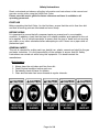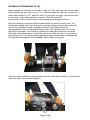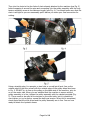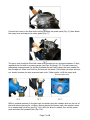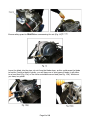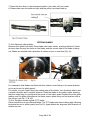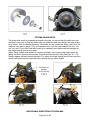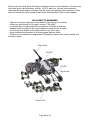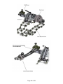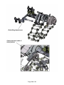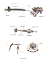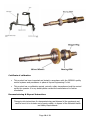
1
OPERATING INSTRUCTIONS FOR N450 Keel Cutter 1. Machine to be operated by trained personnel. 2. Instructions to be read before use. Hy-Ram Mansfield Pelham Street Mansfield Nottinghamshire NG18 2EY Hy-Ram Bury 9 Portland Industrial Estate Portland Street Bury Lancashire BL9 6EY Hy-Ram Enfield Unit 2, Riverwalk Business Park Riverwalk Road Enfield EN3 7QN Hy-Ram Livingston 18 Napier Square Houstoun Road Trading Estate Livingston West Lothian EH54 5DG Tel: 01623 422982 Fax: 01623 661022 Tel: 0161 7641721 Fax: 0161 7620577 Tel: 0208 805 8010 Fax: 0208 805 6010 TEL: 01506 440233 Fax: 01506 440266 Page 1 of 19 Page 2 of 19 SPECIFICATION MACHINE Model: KEEL Cutter N450, Hydraulic version. Type of pipe: Ductile iron, cast iron, cement, plastic and steel (TCT blades must be used for steel). Nominal diameter of pipe: 75mm to 750mm outside diameter. Depth and width of groove: Cutting speed: 2mm x 25mm max. Approx. 80mm to 140mm per minute circumference. Machine dimensions: Weight: 13kgs V-belt: LB24 Height 190mm x width 350mm x length 300mm. HYDRAULIC UNIT: Discharge rate - 16 litres/min Pressure - max. 100 kgs/cm2. Operating oil: Turbine oil #90 Quantity of oil: 22 litres. Weight: 50kgs incl. machine, chains, tools etc. & security box. KEEL N450 Starter Kit includes the following: Machine including hydraulic motor, pulley assembly, 2 x V-belts, 2 x extension chains, 5 x steel wedges, 1 x ratchet, 2 x Allen keys, 1 x spanner, 1 x Safety Valve, 1 x spray bottle with hose and tap. POWERPACK SPECIFICATIONS Page 3 of 19 Safety Instructions Read, understand and observe all safety information and instructions in this manual and exercise caution while using the N450 Keel Cutter. Please save this user's guide for future reference and have it available to all operating personnel. FIRST USE Before operating the Keel Cutter for the first time, ensure that the unit is free from dirt and that all moving parts are lubricated and move freely. BEFORE USING It is important to ensure that all component parts are present and in a serviceable condition. In addition, check that the pipe is of suitable condition and material for the cut to be applied. It is of critical importance to ensure that the pipe is ‘dead’ and not carrying gas, water or any other substance before attempting to cut it. Never use a pipe cutter on pressurised pipe. GENERAL SAFETY This unit is intended for cutting cast iron, ductile iron, plastic, cement and steel for the gas and water industries. It is the responsibility of the operator to ensure that ALL Safety Instructions are carried out while using this equipment. If in doubt contact the manufacturer. Maintenance 1. 2. 1. 2. Always keep the unit clean and free from dirt. Check General condition before each use. Periodically check all items for defects. Clean and lubricate feed screw threads at regular intervals. Page 4 of 19 SETTING UP THE MACHINE TO CUT Before placing the machine on the pipe, make sure that you have the correct blade fitted for the pipe you intend to cut, i.e. a diamond blade for cast iron, ductile iron, plastic and cement or a TCT blade for steel. If you are to cut steel, you will also need an oil mixture in the water spray, for example "Shell Dromus Oil B". and connect the Flow Control Valve to slow cutting speed to approx 250rpm Place the machine on the pipe with the blade above the point you wish to cut. You should have already made sure that there is enough clearance around and under the pipe for the machine to make a complete rotation. This would normally be approximately 210mm in height and 420mm width. The machine must "sit" on the pipe with a solid base. This should be checked by holding the machine by the drive shaft and a comfortable point on the other side of the cutter (see fig. 1), and moving the machine on its four contact wheels backwards and forwards gently, checking that all 4 wheels move together and the Keel is sitting solidly on the pipe. Next, the pulley assembly must be attached onto the drive belts (see Fig 2), trying not to move the cutter from its secure position. Page 5 of 19 Then join the chain to the few links of chain already attached to the machine (see Fig. 3) before wrapping it around the pipe and connecting it to the pulley assembly with the long tension adjusting screw at its maximum length (see Fig. 4). You should make sure that the chain is as tight as you can reasonably pull it before you make your final connection for cutting. Using a straight edge, for example, a steel rule or a small spirit level, line up the outside edge of the drive wheel with the outside edge of the pulley wheel as shown in Fig. 5. DO NOT try to line up the pulley on the blade side of the machine, only do so on the motor side. When you are satisfied that the machine is secure and the pulley assembly is in line, tighten the pulley assembly with the ratchet provided (Fig. 5). There needs to be quite a firm tension on the drive belts, but it is possible to over-tighten, so try to apply a normal fan belt type tension. When this is completed, check again that the drive wheel and the pulley assembly are in line. You are now ready to attach the hydraulic hoses. Page 6 of 19 Connect the hoses to the Keel motor before starting the power pack (Fig. 6), then attach the spray hose and tap to the cutter guard (Fig. 7). The spray unit should be filled with water and pumped up to a pressure between 3-4bar, registered on the built-in pressure gauge (see Figs. 8 through 10). This will ensure an adequately powered water jet will be produced and will last through the time needed for the average cut. Make sure that the jet lands on the blade. If the water jet stops during a cut, simply increase the tank pressure back up to 3-4bar and/or re-fill the spray tank. NB Any residual pressure in the tank can be vented using the release valve on the top of the tank before opening for re-filling. Before starting the power pack, the machine must be in neutral and not drive (see Fig. 11a). With the drive in neutral, turn on the power pack and start the hydraulic flow (Fig. 11b). Page 7 of 19 Ensure safety guard is closed before commencing the cut (Fig. 12). Lower the blade into the pipe; do not force the blade down, as this could cause the blade to buckle. Feed the blade in gently, you will have one of two types of feeds, it will either be a hand feed (Fig. 13a) or the more controllable screw feed (see Fig. 13b). Whichever you have, be gentle! Page 8 of 19 When you are sure the cut is through the pipe wall, check the drive wheel is in line with the pulley and start the drive by pushing the feed valve handle down (see Fig. 14). The Keel will drive itself around the pipe but you will need to keep checking the pulley is in line. If it requires realignment use the hide hammer by tapping the pulley on the side nut, not the wheel, until the pulley is in line. You must also put the steel wedges in the cut at regular intervals around the pipe, such as, 2 o'clock, 4 o'clock, 8 o'clock and 10 o'clock. This will make sure that an even gap is kept around the pipe, thus reducing the pressure on the blade. When the machine has rotated a full circumference, and the blade has met with or just gone past the original cut, stop the drive. Do not turn off the blade rotation until you have removed the blade from the pipe. You may now turn off the power. To remove the machine from the pipe undo the pulley assembly by loosening the threaded bar using the ratchet provided. When there is sufficient slack you can unhook the chains and remove the machine from the pipe. THINGS TO KNOW WHEN CUTTING STEEL PIPE WITH N450 When cutting cast Iron or ductile pipe the motor speed is approximately 600-800rpm which is acceptable for the diamond blade BUT when cutting steel a TCT blade must be used and the maximum speed for this blade is 250rpm.This reduction is achieved by fitting a control valve (Fig. 15) in the hose line before the motor. If you do not have the control valve, please contact South and West Pipe Tools or your supplier who will be pleased to supply one. 1. Set up N450 as per manual until connection of hoses 2. Connect the flexible hoses on the control valve onto quick release couplings on the motor and the hoses from the power pack onto back of valve block. 3. Set control on mark 5,this should be the correct setting for cutting 4. With the drive lever in neutral,(straight out, not up or down)start up power pack and switch on flow 5. Ensure the water hose is connected and suitable soluble oil is mixed with the water to enable easier cutting of steel. Suitable oil would be Shell Dromus oil mixed in the ratio 50:1 water to oil. 6. Start the cut by lowering the blade with the feed screw (a must with cutting steel) gently, not too fast, until cut is through but if the machine seems to be struggling with the cut, set up to mark 6. Page 9 of 19 7. Place the drive lever in the downward position ,the cutter will now rotate 8. Please make sure the belts are tight and the pulley's are kept lined up FITTING BLADES To fit a Diamond cutting blade: Remove drive plate from shaft. Place blade onto cutter holder, ensuring that the 2 holder pins are clean through the holes on the blade, and the correct side of the blade is facing out. Blades are marked with a direction of rotation arrow on one face (Fig. 16). It is imperative that blades are fitted with this rotation arrow facing in the same direction as the arrow on the safety guard. If in doubt, rub your finger along the cutting edge of the blade. You should be able to feel a smooth direction and a rougher direction. Place the blade on the cutter holder ensuring that the rough edge is running with the arrow on the cutter guard. Replace the drive plate, making sure the plate is flat against the blade, secure plate using nut and washers with a firm torque (see Fig. 17 & 18). To fit a Tungsten carbide tipped (TCT) blade: Follow instructions as per diamond blade. The TCT blade must have cutting edge following directional arrow on cutter guard (see Fig 19). Again blades are engraved with direction of rotation arrows. Page 10 of 19 FITTING DRIVE BELTS The drive belts must be inspected at regular intervals, to ensure that the belts have not perished in any way or that the belts have not stretched and gone below the edge of the drive wheel. This is essential because, if the belts for any reason are faulty, the cut of the machine may start to spiral. This, and operator error, are the main reasons for any "run out" of a cut. If you think the belts need to be replaced, both belts must be changed at the same time to ensure even wear. When fitting, follow instructions for removal of blade, then remove the cutter guard by taking out the 2 securing cap screws, this will free the old drive belt (See Figs. 20 - 23). Simply replace belt and reverse process. The other drive belt should just fit onto the drive wheel and should not be restricted from removal by any other object. ROTATIONAL DIRECTION OF THE BLADE Page 11 of 19 Please make sure that when the blade is rotating, it moves in the direction of the arrow on the cutter guard (anti-clockwise, see Fig. 16). If it does not, this can be corrected by removing the quick release couplings from the motor and switching their positions. If this does not correct the fault, please contact South and West Pipe Tools or your supplier. KEY POINTS TO REMEMBER Make sure you are using the correct blade for the pipe you are cutting. When you put the Keel on the pipe, ensure it "Sits solid.” A constant flow of water/coolant is essential on the blade at all times. Wedges must be placed in the cut at regular intervals around the pipe. Do not stop the rotation of the blade until it is out of the pipe. Keep checking the alignment of the drive wheel and the pulley. Ensure you are wearing the appropriate PPE-goggles, gloves, dust mask, overalls and protective boots. Page 12 of 19 Page 13 of 19 Page 14 of 19 Page 15 of 19 Certificate of calibration. • This product has been inspected and tested in accordance with the ISO9001 quality control systems and procedures in place at Hyram Engineering Co Ltd. • This product has no calibration period, periodic, safety inspections should be carried out by the operator if in any doubt please contact the manufacturer for further information Decommissioning & Disposal Instructions These give the instructions for decommissioning and disposal of the equipment and confirm how it is to be taken out of service safely, in respect of the Essential Health and Safety Requirements. Page 16 of 19 • • If a Hyram tool has reached the end of its useful working life and cannot be refurbished it must be disposed of through a licensed scrap or waste disposal facility. Alternatively, a reverse engineering company could be used to strip the equipment for recycling purposes. Disposal is the responsibility of the Customer this can also be achieved by returning the product back to the manufacturer. Warranty Information. 1. Extent of Warranty. (a) Hy-Ram Engineering Co Ltd warrants to the end-user customer that its products will be free from defects in materials and workmanship, for six months after the date of purchase by the end-user customer, subject to providing proof of purchase. If Hy-Ram Engineering Co Ltd receives, during the warranty period, notice of a defect in product which is covered by this warranty, Hy-Ram Engineering Co Ltd shall either repair or replace the product, at its option. Any replacement product may be either new or like-new, provided that it has functionality at least equal to that of the product being replaced. All warranty work will be carried out by Hy-Ram Engineering Co Ltd unless otherwise agreed. On-site warranty and repair or replacement services are available from authorised Hy-Ram Engineering Co Ltd service facilities world-wide. Customers shall prepay shipping charges for products returned to Hy-Ram Engineering Co Ltd for warranty service, and Hy-Ram Engineering Co Ltd will charge for return of the products back to the customer. This warranty statement gives the customer specific legal rights. The customer may also have other rights which vary from country to country in the world. (b) (c) (d) (e) Pre-conditions for Warranty Application. Hy-Ram Engineering Co Ltd’ warranty covers only those defects which arise as a result of normal use of the product, and this warranty shall only apply in the following circumstances: (a) All the instructions contained in the operating manual have been complied with (b) And none of the following apply: (i) (ii) (iii) (iv) (v) (vi) Improper or inadequate maintenance; Physical abuse; Unauthorised modification, misuse or any use not in accordance with the operating manual and good industry practice; Operation outside the products specifications; Improper site preparation or maintenance; and Faulty pipe or fittings. Page 17 of 19 Limitations of Warranty. (a) Hy-Ram Engineering Co Ltd does not warrant the operation of any product to be uninterrupted or error free. (b) Hy-Ram Engineering Co Ltd makes no other warranty of any kind, whether express or implied, with respect to its products. Hy-Ram Engineering Co Ltd specifically disclaims the implied warranties of satisfactory quality and fitness for a particular purpose. (c) To the extent that this warranty statement is inconsistent with the law of the locality where the customer uses the product, this warranty statement shall be deemed modified by the minimum necessary to be consistent with such local law. (d) To the extent allowed by local law, the remedies provided in this warranty statement are the customer’s sole and exclusive remedies. (e) This tool has been designed for the range of fittings available at the time of its design and development. Hy-Ram Engineering Co Ltd can accept NO liability for the unit’s ability or otherwise to work with new or different fittings that subsequently appear in the market place. Page 18 of 19 Please complete this information and keep it safely with your proof of purchase receipt. You will require it for any warranty claim. Where purchased ................................................................................... Date of purchase ................................................................................... Name & address Of purchaser ................................................................................... ................................................................................... ................................................................................... Type of tool ................................................................................... Serial number ................................................................................... For Service and repair please contact: Hy-Ram Mansfield Pelham Street Mansfield Nottinghamshire NG18 2EY Tel: 01623 422982 Fax: 01623 661022 Page 19 of 19