1
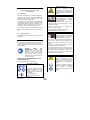
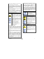
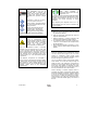
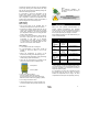
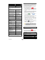
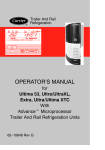
OPERATING INSTRUCTIONS English Vector 1850 E INTRODUCTION This guide has been prepared for the operator of Carrier Transicold refrigeration units. It contains basic instructions for the daily operation of the refrigeration unit as well as safety information, troubleshooting tips, and other information that will help you to deliver the load in the best possible condition. Please take the time to read the information contained in this booklet and refer to it whenever you have a question about the operation of your Carrier Transicold unit. This manual refers to the standard model. Some options may not appear in it, and in such cases you are requested to consult our Technical Services. Your refrigeration unit has been engineered to provide long, trouble-free performance when it is properly operated and maintained. The checks outlined in this guide will help to minimize on the road problems. In addition, a comprehensive maintenance program will help to insure that the unit continues to operate reliably. Such a maintenance program will also help to control operating costs, increase the unit's working life, and improve performance. When having your unit serviced, be sure to specify genuine Carrier Transicold replacement parts for the highest quality and best reliability. At Carrier Transicold, we are continually working to improve the products that we build for our customers. As a result, specifications may change without notice. CONTENTS 1. DESCRIPTION & IDENTIFICATION................................................................................................................... 2 1.1. 1.2. 2. Nameplate .............................................................................................................................................................................. 2 Noise level sticker .................................................................................................................................................................. 2 SAFETY ............................................................................................................................................................. 2 2.1. Warning stickers maintenance ............................................................................................................................................... 4 3. PRODUCT LOADING......................................................................................................................................... 4 4. RECOMMENDED TRANSPORT TEMPERATURES.......................................................................................... 5 5. PRETRIP INSPECTION ..................................................................................................................................... 6 6. DESCRIPTION ................................................................................................................................................... 6 6.1. 7. Display ................................................................................................................................................................................... 6 OPERATION ...................................................................................................................................................... 6 7.1. To start the unit ...................................................................................................................................................................... 6 7.1.1. Standby operation guideline ........................................................................................................................................ 7 7.2. To stop the unit....................................................................................................................................................................... 7 7.3. To change configuration mode ............................................................................................................................................... 7 7.4. To initiate manual defrost ....................................................................................................................................................... 7 7.5. To change set point temperature............................................................................................................................................ 8 7.6. Start-Stop operation ............................................................................................................................................................... 8 7.7. Continuous run operation ....................................................................................................................................................... 8 7.8. Pretrip..................................................................................................................................................................................... 9 7.9. Trip start ................................................................................................................................................................................. 9 7.10. To display unit data ................................................................................................................................................................ 9 7.11. To change a function.............................................................................................................................................................. 9 7.12. To display fault alarm ........................................................................................................................................................... 10 7.12.1. Alarm list.................................................................................................................................................................... 10 8. MAINTENANCE ............................................................................................................................................... 11 8.1. 8.2. Maintenance schedule ......................................................................................................................................................... 11 Service description ............................................................................................................................................................... 11 9. A.T.P. EUROPE REGULATION EXTRACT ...................................................................................................... 11 10. 24H ASSISTANCE ........................................................................................................................................... 12 62-61149-01 1 1. DESCRIPTION & IDENTIFICATION Keep the fold out sheet while reading the instructions. 1.1. Nameplate Each unit is identified by a nameplate attached to the frame of the unit. The nameplate identifies the complete model number of the unit, the serial number and some other information. If a problem occurs, please refer to the information on this plate, and make a note of the model and serial number before calling for assistance. This information will be needed when you contact a technician so that he may properly assist you. The complete nameplate (1a) is fixed on the frame and the Serial Number is fixed on the control box (1b). 1.2. Noise level sticker This sticker indicates the noise level in Lwa (sound power level). 2. SAFETY This manual contains safety and service instructions to follow in order to prevent any accident. Some of following stickers have been placed on the product for your SAFETY. i BEFORE USING THIS REFRIGERANT UNIT, read carefully all safety information explained in this manual and indicated on the product. Be sure that everybody who will use this refrigeration unit has been trained to use it in a safe way. DURING THE USE OR MAINTENANCE OF THIS REFRIGERATION UNIT, the notes on safety are to be considered. Personal protective equipment : . Always use adequate Personal Protective Equipment before doing anything on this refrigerant unit, as explained in this manual. . Hearing protection is recommended when unit is running. 62-61149-01 Working at height : Take all necessary safety precautions when accessing this refrigeration unit: use safe ladders, working platforms with appropriate guards. Automatic start : This refrigeration unit is equipped with Auto-Start/Stop, a valuable fuel saving feature. Before servicing refrigeration unit, make sure the main power switch is on the OFF position. Ensure the unit will not restart. Lock-out / Tag-out can disconnecting and enclosing: be performed by - the negative battery cable in diesel mode - the electrical plug in electrical mode Belts and fans : This refrigeration unit is equipped with Auto-start/stop, it may start at any time and without warning. When the unit is running beware of belts and fans that are moving. Before servicing refrigeration unit, make sure the main power switch is on the OFF position. Ensure the unit will not restart. Lock-out / Tag-out can be performed as described above. When there is protective structure (fan grid or guard for example) make sure they are in place. Never removed them when the refrigeration unit is running. Always keep your hands, body parts, clothes, hairs and tools far from moving parts. Electricity : When this refrigeration unit is running in electrical operation, some devices are powered up especially in the electrical control box. . Always use adequate tools and Personal Protective Equipment when working on electrical devices: safety gloves and safety glasses. 2 Before servicing refrigeration unit, make sure the main power switch is on the OFF position. Ensure this refrigeration unit is disconnected from the local electrical network. Lock-out / Tag-out can be performed as described above. Before working in the electrical control box, it is required to control the absence of tension. Ensure that all condensers are discharged before service to avoid electric shock. WHEN IT IS NECESSARY TO WORK IN THE ELECTRICAL CONTROL BOX UNDER TENSION, PEOPLE MUST BE QUALIFIED FOR WORKS UNDER LOW OR HIGH VOLTAGE. Refrigerant : The refrigerant contained in this refrigeration unit can cause frostbite, severe burns or blindness in case of projection and direct contact with the skin or eyes. In contact with flame or heat, refrigerant generates toxic gas: keep any flame, any lighted object or any source of sparks away from the refrigerant unit. Always use Personal Protective Equipment when handling refrigerant: safety clothes, safety gloves and safety glasses. Refrigerant handling must be done by qualified people. Refrigerant Use & Handling •Combustibility - Certain HFC & HCFC refrigerants can become combustible when mixed with high concentrations of air at elevated pressures. This not only includes R-22, but also many other HFC & HCFC refrigerants. For example, this is also true of R-134a. •Therefore, these refrigerants should not be mixed with air under pressure for leak testing or other purposes. soldering in the presence of refrigerant vapors, stop work immediately and ventilate the area. This flame effect only occurs at dangerously high concentrations of refrigerant vapors. This could create the inhalation hazards noted above. •Skin & Eye Protection - Contact with “liquid” refrigerants can result in immediate freezing of the tissues, and permanent damage or blindness can result. DO NOT handle liquid refrigerants without proper personal protective equipment. DO NOT cut into any refrigerant lines under pressure. DO NOT open valves or vent equipment where you may be sprayed with liquid refrigerant. Cooling oil : - avoid prolonged or repeated contact with the skin. - wash carefully after handling. Burning with hot and cold : When this refrigeration unit is running or even after, different components can be very cold or hot (exhaust pipe, tubes, coils, receiver, accumulator or engine for example) Beware when operating closed from cold or hot components. Always use adequate safety gloves when doing any maintenance on this refrigeration unit. Cuttings : Beware when handling or operating closed from parts that could be sharp (coils, evaporators, clamps for example). Always use adequate safety gloves when doing any maintenance on this refrigeration unit. •Inhalation Hazards - All refrigerants are hazardous if inhaled in concentrations exceeding the recommended safe limits. The symptoms include: headaches, nausea, sleepiness, lethargy, dizziness and loss of coordination. It can result in irregular heartbeat, unconsciousness and even death. The proper remedies should be taken to eliminate or reduce the exposures. •Flame Enhancement - If you see a change in the color or size of the torch flame while welding or 62-61149-01 3 Battery : Environment : This refrigeration unit may be equipped with a lead-acid type battery. When charging the battery normally vents small amounts of flammable and explosive hydrogen gas. Think about protection of environment during all the life of this refrigeration unit. Projections of acids on the skin or eyes can cause severe burns. To prevent environmental damages NEVER release refrigerant in the atmosphere, NEVER throw coolant, oil, battery and chemicals in the nature. It must be recuperate and recycle according to current regulations. Keep any flame, any lighted object or any source of sparks away from the battery elements. When disposing this refrigerant unit do it in an environmentally sound way and in accordance with current regulations. Always use Personal Protective Equipment when handling and charging battery: safety clothes, safety gloves and safety glasses. 2.1. Respect polarity when connecting a battery. CAUTION Under no circumstances should anyone attempt to repair the Logic or Display Boards. Should a problem develop with these components, contact your nearest Carrier Transicold dealer for replacement. Under no circumstances should a technician electrically probe the processor at any point, other than the connector terminals where the harness attaches. Microprocessor components operate at different voltage levels and at extremely low current levels. Improper use of voltmeters, jumper wires, continuity testers, etc. could permanently damage the processor. Most electronic components are susceptible to damage caused by electrical static discharge (ESD). In certain cases, the human body can have enough static electricity to cause resultant damage to the components by touch. This is especially true of the integrated circuits found on the truck/trailer microprocessor. Warning stickers maintenance a. Keep the warning pictograms clean and without any obstruction material. b. Clean the pictograms with water and soap and wipe them with soft fabric. c. Replace damaged or missing pictograms with new pictograms available in Carrier network. d. If a component having a pictogram is replaced by a new one, be sure that the new component has the right pictogram. e. Place a warning pictogram by applying it on a dry surface. Press to external sides to eliminate air bubbles. 3. PRODUCT LOADING Proper air circulation in the insulated box, air that can move around and through the load, is a critical element in maintaining product quality during transport. If air cannot circulate completely around the load: hot spots or top-freeze can occur. The use of pallets is highly recommended. Pallets, when loaded so air can flow freely through the pallets to return to the evaporator, help protect the product from heat passing through the floor of the truck. When using pallets, it is important to refrain from stacking extra boxes on the floor at the rear of the truck, because this will cut off the airflow. Product stacking is another important factor in protecting the product. Products that generate heat, fruits and vegetables for example, should be stacked so the air can flow through the product to remove the heat; this is called "air stacking" the product. Products that do not create heat, meats and frozen products, should be stacked tightly in the centre of the box. 62-61149-01 4 All products should be kept away from the sidewalls of the body, allowing air to flow between the body and the load; this prevents heat filtering through the walls from affecting the product. NOTE : For stationary utilization, we recommend to place the body in the shade. It is important to check the temperature of the product being loaded to ensure that it is at the correct temperature for transport. The refrigeration unit is designed to maintain the temperature of the product at the temperature at which it was loaded; it was not designed to cool a warm product. SOME ADVICE Before loading ! 4. • Pre-cool the inside of the insulated body by lowering the temperature for about 15 minutes. • Evacuate the humidity existing inside the box by carrying out a manual defrost. This can only take place when enabled by the defrost thermostat (box temperature lower than 3°C during pull down and 8°C during heating). • Evaporator fans are protected by safety grills. In the event of heavy duty use of the unit, ice can accumulate on the grills. It is therefore recommended to clean them regularly by means of a small brush. The operation MUST be done when the unit has been SHUT DOWN. When loading • To be carried out with the unit stopped. • It is recommended to open doors as little as possible to avoid the intake of hot air and humidity. • Select the temperature by means of the thermostat, according to the transported goods. • Check the internal temperature of the goods being loaded (using a probe thermometer). • Take care not to obstruct the air intakes on the evaporator section and the ventilation ducts. Load spacers Load on pallets • Leave a free space of about : - 6 to 8 cm between load and front wall, - 20 cm between the top of the load and the roof, - between the floor and the load (gratings, pallets). IMPORTANT Never leave your unit more than a month without running. RECOMMENDED TRANSPORT TEMPERATURES Below are some general recommendations on product transport temperatures and operating modes for the unit. These are included for reference only and should not be considered pre-emptive of the set-point required by the shipper or receiver. More detailed information can be obtained from your Carrier Transicold dealer. Product Bananas Fresh fruits and vegetables Fresh meats and seafood Dairy products Ice Frozen fruits and vegetables Frozen meats and seafood Ice cream Set point range 15°C (60°F) +4°C to +6°C (+39°F to +43°F) +2°C (+36°F) +2°C to +6°C (+36°F to +43°F) -20°C (-4°F) Operating mode* Continuous Continuous Auto-Start/Stop or continuous Auto-Start/Stop or continuous Auto-Start/Stop Auto-Start/Stop -18°C (0°F) Auto-Start/Stop -20°C (-4°F) -25°C (-13°F) Auto-Start/Stop * During delivery cycles that include frequent stops and door openings, it is recommended that the unit always be operated in the continuous run mode to help insure product quality It is essential to shut down the compartment during the periods when the doors are open, in order to maintain the temperature of the cargo in the other compartments and keep the unit operating correctly. • Do not forget to close the doors. • Before closing the doors, check your load once more and see that nobody is shut inside the box. 62-61149-01 5 5. 6. PRETRIP INSPECTION The pre-trip inspection should be performed before picking up any load. This inspection is essential to anticipate and help minimize the possibility of "onthe-road" problems. These checks take only a few minutes. 1. 2. 3. 4. 5. DESCRIPTION Keep the fold out sheet while reading the instructions. 6.1. Display 1. Mode lights 2. Display Battery - On units equipped with serviceable batteries, the level of the electrolyte in each of the cells should be checked. If the level is low, distilled water should be added to the correct level. Most units, however, are equipped with low or maintenance-free batteries; these should be inspected to ensure that the connections are clean and tight, and the battery hold-down should be checked for tightness. 3. Up and down arrow keys 4. Equal key 5. Message centre 6. Manual defrost key 7. Alarm key Over-all Unit inspection - Visually inspect the entire unit for leaks, loose bolts, frayed, loose, or broken wires, etc. The radiator and condenser coils of the unit should be free of dirt, bugs, cardboard, or any other debris that may obstruct airflow across the coils. The evaporator (located inside the body) should be free of debris also, especially stretch-wrap, which is often used during transport to prevent cargo from shifting. 8. Start/stop-continuous key 9. Select key Place the unit's main power switch to the Stop position. Truck body - The body should be inspected prior to loading. Check the door and vent seals for damage and wear. Inspect the entire interior and exterior of the body to detect any damage, including the inner and outer skins of the body. Damage to the insulation may compromise the unit's ability to maintain the product temperature by increasing the amount of heat gain in the box. 10. Run/Stop switch 11. Language switch 7. OPERATION 7.1. To start the unit 1. Connect a standby cable to the unit. (See section 7.1.1) Pretrip – to Initiate a pretrip: ) to enter the 2. To power up the unit, place the circuit breaker main switch on "ON". b) Press UP ( ) or DOWN ( ) arrow until Pretrip appears in the message centre. 3. Place the RUN/STOP switch microprocessor controller to RUN. 4. Toggle the LANGUAGE switch as soon as you select 1 of the 9 available languages: English French - Spanish - German - Danish - Dutch Italian - Russian and Polish. a) Press the SELECT key ( scrolling menu c) Press the EQUAL key ( Pretrip. ) to start on the NOTE The unit is fitted with an automatic phase reverser. In all cases, the electric motor will run in the correct direction. 62-61149-01 6 7.1.1. Standby operation guideline For safe, reliable operation in Standby mode, it is important to consider the following guideline: a) ALWAYS check that the unit is OFF (Cab command) before connecting or disconnecting it from the power source. b) The extension cable and fuse used for network connection must comply with the legislation currently applicable on the site of use (minimum H07 RNF CEI 245-4) and with the unit specifications as described in the table below: Fuse aM 400 / 3 / 50 Hz aM: Motor rated fuse 32 A Standardized extansion cable H.07.RNF 400 V 6 mm2 c) The unit connection cable must be fitted with a ground connection. The cable must be connected to earth. d) On the 400 V supply, the unit MUST BE CONNECTED to a high sensibility (30mA) differential protection. e) When performing service and/or maintenance procedures on a refrigeration unit, make certain that the unit is disconnected from the power source and that the keypad correctly indicates OFF", and that it is impossible for the unit to start up automatically during the maintenance operation. f) Operations on the 400 V supply for the unit must only be carried out by authorized personnel. Frozen minimum Off Time 30 min 45 min Frozen Override T° 4°C 5°C 1. Press the SELECT key ( scrolling menu. 2. Press UP ( ) or DOWN ( select CoolSET or EcoFUEL. 3. Press the EQUAL key ( selected configuration. 7.4. ) to access the ) arrow to ) to validate To initiate manual defrost The defrost mode may be initiated in three different ways if the evaporator coil is below 4.5°C (40°F): 1. Defrost is initiated automatically at preset intervals by defrost timer in the microprocessor. 2. Defrost is initiated by the defrost air switch. 3. The defrost mode may be manually initiated by ). pressing the Manual Defrost Key ( The DEFROST Light will come on and the message centre will display "DEFROST CYCLE STARTED" for 5 seconds. If "CANNOT START DEFROST CYCLE" is displayed, the coil temperature is above 4.5°C (40°F). Run the unit to lower temperature below 4.5°C (40°F) and then restart defrost. g) The user is liable for ensuring that the above measures are taken. All defrost modes with heater bars terminate when the evaporator temperature is higher than 12.5°C (55°F). 7.2. Natural defrost mode terminates when Return Air Temperature is equal to Supply Air Temperature. To stop the unit To stop the unit, place the RUN/STOP switch on the microprocessor controller keypad to STOP. 7.3. To change configuration mode In order to optimize unit performance, 2 different sets of configuration are available on Vector unit: - CoolSET: recommended for sensitive products - EcoFUEL: recommended for any other kind of products CoolSET mode (factory set by default EcoFUEL mode Perish minimum Off Time 20 min 30 min Perish override T° 3°C 4°C 62-61149-01 Should the defrost cycle not complete within 45 minutes, the defrost cycle is terminated. "A54DEFROST NOT COMPLETE" will be in the Message Centre. After the 45 minute termination, the controller will wait 1.5 hours before attempting another defrost cycle. Pressing the manual defrost key will override this mode and start a new 45 minute defrost cycle. Overriding this 1.5 hour waiting period will generate an alarm. If a shutdown alarm occurs, defrost will be terminated. 7 7.5. To change set point temperature 1. With the set point displayed, press the UP ( ) ) ARROW key to change set point to or DOWN ( the desired value. The display will flash to indicate that the set point reading being displayed is a non-entered value. The message centre will show "↑↓TO SCROLL, THEN = TO SAVE". The set point display will flash for 5 seconds of until the EQUAL key is pressed. 2. Press the EQUAL/ENTER ( new set point. ) key to save the 3. Verify that the message "SET POINT CHANGED" is displayed on the message centre for 5 seconds. Remarks : - Set points of -30°C to +32°C (-22°F to +89°F) may be entered via the keypad. The controller always retains the last entered set point in memory. -Set point can not be changed when unit is in Pretrip or when viewing Alarm List, Data List or Functional Parameters. ) will cause the -Depressing the EQUAL key ( new displayed set point value to become active. If the display is flashing and the new value is not entered, after 5 seconds or no keyboard activity, the display will flash for 10 seconds with "SET POINT NOT CHANGED" displayed and then revert back to the last set point. All other keys are active at this time and may be pushed while the display is flashing. TIP You may press and hold the UP or DOWN arrow key to change the set point. The longer the key is held, the faster the setting will change. 7.6. Start-Stop operation 1. Press the START/STOP CONTINUOUS key ( ) until the START/STOP Light (2.) on the controller illuminates. Configuration parameter for S/S parameters : SEPARATE : • The unit will start for a minimum run time based on the Perish Min Run Time of Frozen Min Run Time functional parameter. • The unit will stop for a minimum off time based on the Perish Min Off Time or Frozen Min Off time functional parameters, and for a maximum off time based on the Perish Max Off time or Frozen Max Off Time functional parameters. • If the Max Off time is Off, there is not maximum off time. Configuration parameter for S/S parameters : TOGETHER : • The unit will start for a minimum run time based on the Perish Min Run Time functional parameter. • The unit will stop for a minimum off time based on the Perish Min Off time functional parameters, and for a maximum off time based on the Perish Max Off time functional parameters. • If the Max Off Time is Off, there is no maximum off time. Continuous Run : only for set point above -12°C (≤12°C) 7.7. Continuous run operation 1. Press the START/STOP CONTINUOUS key ) until the CONTINUOUS RUN Light (2.) ( on the controller illuminates. 2. Verify that "CONTINUOUS RUN MODE SELECTED" is displayed on the message centre and that the CONTINUOUS RUN Light is illuminated. The unit is now in Continuous Run operation. Remarks: - In the continuous run mode, the diesel engine will not shut down except for safeties or if the engine stalls. Continuous Run operation is normally used for perishable loads. - If pressing the START/STOP CONTINUOUS key seems to have no affect, this key may be locked out. Start-Stop and Continuous operation may be tied to the set point ranges for frozen and perishable loads. 2. Verify that "START/STOP MODE SELECTED" is displayed on the message centre for 5 seconds and that the START/STOP Light is illuminated. The unit is now in Start-Stop operation. 62-61149-01 8 7.11. To change a function 7.8. Pretrip The PRETRIP mode is for checking unit operation and evaluating operation of all modes and indicating a failure when detected. 1. Press the SELECT key ( ) until "PRESS ↑↓ TO VIEW SETTINGS" appears in the Message Centre. The message centre displays the current test and the % complete of the test. When the Pretrip tests are complete the message centre will display "PRETRIP PASS" or "PRETRIP FAIL IN TEST<test number>". If "PRETRIP FAIL IN TEST<test number>" is displayed the ALARM light will flash. Press the ALARM LIST key to review the alarms set by the Pretrip tests. 2. Press the UP ( ) or DOWN ( ) arrow to scroll through the Function List beginning at the top or the bottom. Once Pretrip is started, the control panel keys are disabled until the Pretrip ends. 1. Press the SELECT key ( ) until "PRESS = TO START PRETRIP" is displayed. 2. Press the = key ( ) to start PRETRIP. 3. Verify that the display shows "TEST#". 7.9. Trip start Trip start marks a time stamp in memory to allow easy review of the data from the last trip. This function tells the recorder that the present date and time is beginning of a new trip. 1. To mark the start of a trip in the data recorder, ) until "PRESS = TO press the SELECT key ( MARK TRIP START" is displayed. 2. Press the = key ( ). 3. If trip start is acknowledged by the data recorder, "TRIP START ENTERED" will be displayed for 5 seconds and then the display will revert back to the normal display. Otherwise "CANNOT ENTER TRIP START" will flash and then the display will revert back to the normal display. 7.10. To display unit data 1. Press the SELECT key ( ) until " PRESS ↑↓ TO VIEW DATA" is displayed. 2. Press the = key ( 3. 4. To read through the Function List, continue to press either the UP or DOWN ARROW key. The Functional Parameters will appear in the Message Centre in the order as shown below. The list is circular meaning that once the end is reached, it is repeated from the beginning. If no key presses are made for 10 seconds, the Message Centre will return to the default message. 5. To change one of the Functions, bring the Function you wish to change into the Message ) key "↑↓ TO Centre and press the EQUAL ( SCROLL, THEN = TO SAVE" will appear in the Message Centre. 6. Press either UP ( ) or DOWN ( ) ARROW key to begin to change the Function setting. The Message Centre will flash, indicating that a change has been made that has not been entered into memory. ) or DOWN ( ) 7. Continue pressing UP ( key until the desired value is showing, then press the EQUAL ( ) key. The Message Centre will stop flashing. The new value is now in memory. CAUTION ! If the key is not pressed within 10 seconds, the Message Centre will change to "FUNCTION NOT CHANGED". This will appear for 5 seconds, then return to the last Functional Parameter shown. If no further keys are pressed, the default display will return in another 10 seconds. ) to enter unit data menu. ) or DOWN ( Press UP ( display the requested data. 62-61149-01 3. "↑↓ TO SCROLL, THEN = TO SELECT" will appear in the Message Centre. ) arrow to 9 7.12. To display fault alarm Functional parameter Available selection Selection in BOLD are the factory settings "DEFROST TIMER SET FOR" 1.5 hrs / 3 hrs / 6 hrs / 12 hrs "SET S/S PARAMETERS:" (These may be displayed individually (8 parameters) as PERISH and FROZEN, or combined (4 parameters) with no designation.) "PERISH MIN RUN TIME:" "FROZEN MIN RUN TIME:" 4 mins to 60 mins (in 1 minute increments) "PERISH MIN OFF TIME:" "FROZEN MIN OFF TIME:" 10 mins to 90mins 20 minsdefault (in 1 minute increments) "PERISH OVERRIDE TEMP:" "FROZEN OVERRIDE TEMP:" 2°C to 10°C (38.5°F to 50°F) 4°C (40°F) default (in 0.5°C increments) "PERISH MAX OFF TIME:" "FROZEN MAX OFF TIME:" OFF / 10 mins to 255mins (in 1 minute increments) "FROZEN SHUTDOWN:" "OFFSET:" 0°C to 2°C (32°F to (38.5°F) "TEMP CONTROL:" "RETURN AIR" / "SUPPLY AIR" "DISPLAY IN" "ENGLISH" UNITS / "METRIC" UNITS Unit problems detected by the controller are stored in the Alarm List in the controller. Stored alarms may be viewed in the Message Centre. All most times, the "STATUS OK" message will be shown in the Message Centre. 1. Press the ALARM LIST key ( ). If there are no active alarms in the alarm list, the message "NO ACTIVE ALARMS" will be displayed for 5 seconds. If there are active alarms in the alarm list, the display will be "A" and the alarm message for the latest active alarm in the list for 5 seconds. 3. Press the UP ( ) or DOWN ( scroll through the alarm list. ) key to 4. When you reach the end of the alarm list, "LIST END, = TO CLEAR ALARMS" is displayed. 5. If the alarm list is full, the "A" and the alarm message for the latest alarm is displayed for 5 seconds, then "LIST END, = TO CLEAR ALARMS" is displayed for 5 seconds. * "SET PM HOURMETERS:" "ENGINE" "SWITCH ON" PM 1 thru PM 55 ON / OFF / RESUME / RESET- "STANDBY" "SWITCH ON" PM 1 thru PM 55 ON / OFF / RESUME / RESET - "OUT OF RANGE ALARM:" OFF / 2°C (4°F) / 3°C (5.5°F) / 4°C (7°F) "C2 OUT OF RANGE ALARM:" OFF / 2°C (4°F) / 3°C (5.5°F) / 4°C (7°F) "C3 OUT OF RANGE ALARM:" OFF / 2°C (4°F) / 3°C (5.5°F) / 4°C (7°F) "SLEEP MODE: NO / YES * "OVERRIDE DOOR SHUTDOWN:" NO / YES * "OVERRIDE REMS1 SHUTDOWN:" * "OVERRIDE REMS2 SHUTDOWN:" NO / YES "SILENT MODE" NO / YES "ECO MODE: YES" or "ECO MODE: NO" NO / YES "NO POWER-SWITCH TO DIESEL:" NO / YES * This Functional Parameter may not appear in the list for your unit, depending on microprocessor configuration. 62-61149-01 6. To deactivate the active alarm list, press the ) while "LIST END, = TO EQUAL key ( CLEAR ALARMS" is being displayed. TIP To deactivate active alarms, turn the controller OFF and then back ON using the RUN / STOP switch. 7.12.1. Alarm list If there is a safety shutdown, "UNIT SHUTDOWNSEE ALARM LIST" will be shown. Pressing the ALARM LIST key ( ) will bring any Active Alarms into the Message Centre. The following are the Shutdown Alarms that may appear: Alarm message √: alarm only X or √: depends on the configuration X: Shutdown Driver alarms "2-LOW ENGINE OIL LEVEL" (option) Shutdown alarms "11-LOW ENGINE OIL PRESSURE" "12-HIGH COOLANT TEMPERATURE" "13-HIGH DISCHARGE PRESSURE" "14-ELECTRIC CIRCUIT" "15-BATTERY VOLTAGE TOO HIGH" status X or √ X or √ X X X 10 "16-BATTERY VOLTAGE TOO LOW" "17-HIGH COMP DISCHARGE TEMP" "18-LOW REFRIGERANT PRESSURE" "19-LOW FUEL SHUTDOWN" "22-LOW SUCTION SUPERHEAT" "23-A/C CURRENT OVER LIMIT" "27-HIGH SUCTION PRESSURE" "28-CHECK REFRIGERATION SYSTEM" Start up engine alarms "30-FAILED TO RUN MINIMUM TIME" "31-FAILED TO START-AUTO MODE" "32-FAILED TO START-MANUAL" "39-CHECK ENGINE RPM" "35-CHECK STARTER CIRCUIT" "41-ENGINE STALLED" Warning status alarms "51-ALTERNATOR NOT CHARGING" "62-C2 BOX TEMP OUT-OF-RANGE" -V1850 Mt° "63-C3 BOX TEMP OUT-OF-RANGE" -V1850 Mt° Electrical alarms "73-NO POWER- CHECK POWER CORD" "74-AC PHASE REVERSED" "75-COMP MOTOR OVERHEATED" "76-CONDENSER MOTOR OVERHEATED" "77-EVAP MOTOR OVERHEATED" "98-CHECK HIGH TEMP THERMOSTAT" Sensor alarms "122-CHECK RETURN AIR SENSOR" "123-CHECK SUPPLY AIR SENSOR" Microprocessor alarms "232-SETPOINT ERROR" "233-MODEL # ERROR" "237-FUNCTION PARAMETER ERROR" "238-CONFIGURATIONS ERROR" "242-DIS PRESS CALIBRATE ERROR" "243-SUCT/EVAP CALIBRATE ERROR" "244-ECONO CALIBRATE ERROR" "245-CAN NOT SAVE SETTING" "246-EEPROM WRITE FAILURE" "248-CONFIG MODE / HP2 ERROR" "249-MICROPROCESSOR ERROR" 8. X X X or √ X or √ X X X or √ X or √ X X X X or √ X or √ X X or √ X or √ X or √ X X or √ X X X X both electric heater X X X X X X X X X X X X Maintenance schedule 1 month every 6 months every 2 years 8.2. Vector 1850 E Initial service Service A Service B Service description •Check the tightness of bolts and screws and that the unit is correctly fastened onto the box •Tighten all electrical connection in control box •Pretrip inspection •Operation of Initial service •Calibrate defrost air switch •Clean evaporator and condenser coils •Check level of refrigerant and battery Service A electrolyte 6 months •Check battery charger charge •Check thermostat operation •Check manual/automatic defrost operation •Check klixon cut out •Complete operation of Service A + •Replace filter drier. Service B •Clean up the expansion orifice filter. Every 2 •Replace compressor oil – only use years Ester oil (POE) approved by Carrier Transicold. •Replace refrigerant. Initial service 1 month 9. A.T.P. EUROPE REGULATION EXTRACT (Date: March 1974) Approval of vehicles intended for the carriage of perishable goods. MAINTENANCE A comprehensive maintenance program will help to insure that the unit continues to operate reliably. Such a maintenance program will also help to control operating costs, increase the unit's working life, and improve performance. NOTE All maintenance services must be done by a technician trained on Carrier products respecting all safety and quality standards of Carrier. Before any operation requiring an intervention on the unit, check that: - the unit is OFF - It is impossible for the unit to automatically startup during maintenance. 62-61149-01 8.1. Before putting a refrigerated vehicle into service, it is necessary to have it approved by the Regional Health Department. Characteristics of vehicles used perishable goods; refrigeration unit. for carrying The refrigeration unit is an insulated unit with a cooling system which makes it possible, with a mean outside temperature of +30°C, to lower the temperature inside the empty body and to maintain this low temperature in the following way: class A : Refrigeration unit furnished with a cooling system whereby a temperature between +12°C and 0°C inclusive can be chosen. class B : Refrigeration unit furnished with a cooling system whereby a temperature between +12°C and –10°C inclusive can be chosen. 11 class C : Refrigeration unit furnished with a cooling system whereby a temperature between +12°C and –20°C inclusive can be chosen. The cooling capacity of a unit is determined by a test carried out in one of the approved testing stations and ratified by an official report. Note: The "K" factor of bodies intended to be classified as C must be equal to or lower than 0.4 W/m2 °C. Signs, identification marks and plates to be attached to refrigeration units. Refrigeration Plate This reference must be followed by identification marks according to the following list: Standard refrigeration unit Class A FNA Reinforced refrigeration unit Class A FRA Reinforced refrigeration unit Class B FRB Reinforced refrigeration unit Class C FRC In addition to the above identification marks, the date (month and year) of expiry of the approval certificate must be indicated. Example: FRC 6-2007 (6 = month (June) 2007 = year) Very important Regularly check the expiry date of the approval certificate. During transport, the approval certificate or provisional certificate should be shown on request of qualified agents. To have an insulated unit approved as a refrigeration unit, an application to modify the approval certificate should be sent to the regional health office. 10. 24H ASSISTANCE At Carrier Transicold we're working hard to give you complete service when and where you need it. That implies a worldwide network of dealers and available an emergency service. These service centres are manned by factory-trained service personnel and backed by extensive parts inventories that will assure you of prompt repair. In Europe, please use the following free phone numbers from: A B CH D DK E F FIN GB GR H I IRL L RUS N NL P PL S AUSTRIA BELGIUM SWITZERLAND GERMANY DENMARK SPAIN FRANCE FINLAND GREAT BRITAIN GREECE HUNGARY ITALY IRELAND LUXEMBURG RUSSIA NORWAY THE NETHERLANDS PORTUGAL POLAND SWEDEN 0800 291039 0800 99310 0800 838839 0800 1808180 808 81832 99 993213 0800 913148 0800 113221 0800 9179067 00800 3222523 06800 13526 800 791033 1800 553286 800 3581 810 800 200 31032 800 11435 0800 0224894 8008 32283 00800 3211238 020 790470 From other countries / Direct : +32 9 255 67 89 In Canada or United States, call 1 – 800 – 448 1661 When calling, please have the following information ready for fastest service: • • • • • Your name, the name of your company, and your location A telephone number where you can be called back Refrigeration unit model and serial number Box temperature, set point and product Brief description for the problem you are having and what you have already done to correct the problem. We will do everything we can to get your problem taken care of and get you back on the road. Should you encounter a unit problem with your refrigeration unit during transit, follow your company's emergency procedure or contact the nearest Carrier Transicold service centre. Consult the directory to locate the service centre nearest you. This directory may be obtained from your Carrier Transicold dealer. If you are unable to reach a service centre, call Carrier Transicold’s 24Hour Assistance: 62-61149-01 12