1
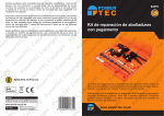
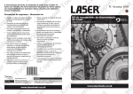
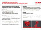
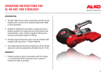
OPERATING INSTRUCTIONS FOR AL-KO 4X4 REPLACEMENT STABILISER HANDLE INTRODUCTION KIT CONTENTS 1 These instructions are for use of the 4x4 handle only. They should be read in conjunction with the Assembly & Operating Instructions, which was supplied with your stabiliser. If you do not have a copy, please request one from our Service Department or download it from www.al-ko.co.uk. 1 Replacement handle 2 Torx spanner 2 When not in use (during travelling or storage), the handle MUST be removed from the stabiliser and stored within your vehicle. Providing the stabiliser has been coupled correctly, the removal of the handle from the stabiliser arms will not interfere with the normal operation of the stabiliser. 1 Remove the existing stabiliser handle: Using the torx spanner provided, undo and remove the fixing screw located on the side of the red handle. The red handle should now pull off the stabiliser lever arms. 3 Only suitable for the AKS 2004/3004 Stabiliser as shown in Fig 1. WARNING THE 4X4 HANDLE GRIPS ON TO THE LEVER ARMS BY MEANS OF SPRING LOADED BALL BEARINGS INSIDE THE HANDLE. THIS HANDLE IS NOT DESIGNED TO BE PERMANENTLY FIXED TO THE LEVER ARMS OF THE STABILISER. FAILURE TO REMOVE THE HANDLE WHILST TRAVELLING COULD RESULT IN A SAFETY HAZARD TO OTHER ROAD USERS. IT COULD ALSO BECOME AN OBJECT LIABLE TO THEFT. ASSEMBLY Fig 1 AL-KO Security Device 2 To fit: Ensure both stabiliser lever arms are level and using gentle force, push the 4x4 handle on to the lever arms. 3 To remove: Use gentle force, grip the handle firmly and pull the handle backwards and away from the lever arms. Fig 1 AL-KO Security Device Fig 1 AL-KO Security Device OPERATING INSTRUCTIONS FOR AL-KO 4X4 REPLACEMENT STABILISER HANDLE COUPLING UP USING 4X4 HANDLE UNCOUPLING USING 4X4 HANDLE 1 With the 4x4 handle in place, raise the stabiliser lever arms to 45º and remove the handle from the stabiliser (Fig 3). 1 Reattach the 4x4 handle to the stabiliser lever arms (Fig 5). 3 Couple up to the towball as normal. 4 With the stabiliser now coupled up, pull the arms down to 45º and reattach the 4x4 handle before pushing the stabiliser arms down fully, locking the friction pads onto the towball. 5 Remove 4x4 handle from stabiliser and store in tow vehicle. 2 With the 4x4 handle in place, raise the stabiliser arms 45º to disengage the friction pads from the towball (Fig 6). 3 Remove the 4x4 handle (Fig 3). 4 With the 4x4 handle removed push the stabiliser arms to 90º and uncouple from the towball as normal (Fig 4). 2 With the 4x4 handle removed, push the stabiliser lever arms into the upright position and raise the coupling handle (Fig 4). Fig 5 Slide handle over stabiliser arms Fig 6 Raise stabiliser arms to 45º AL-KO Kober Ltd, South Warwickshire Business Park, Kineton Road, Southam, Warwickshire, CV47 OAL E-Mail: [email protected] www.AL-KO.co.uk Tel: 01926 818500 Fig 3 Slide handle off the stabiliser arms Fig 4 Handle removed, arms at 90º Due to a policy of continuous improvement, AL-KO reserves the right to change technical specifications. Part No. 1389609 Iss. 3 07/12