1
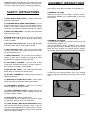
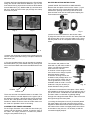
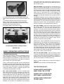
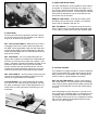
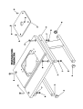
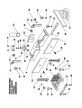
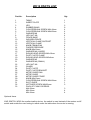
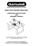
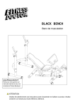
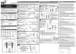
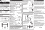
ROUTER TABLE W012
OPERATING INSTRUCTIONS
AND
ASSEMBLY MANUAL
The Charnwood router table enables any portable router to be inverted
and used as a stationary machine capable of producing many different
types of joints and decorative finishes.
Charnwood, 1 Rowan Street, Leicester, LE3 9GP, England
Tel. 0116 251 1550 Fax. 0116 253 2891 e-mail; [email protected]
UK customers can view our full product range at www.charnwood.net
WARNING; When using electric tools, basic safety precautions should be followed to reduce risk of fire, electric shock, and personal injury, including the following:
ASSEMBLY INSTRUCTIONS
Part number are shown in brackets, for example (12)
SAFETY INSTRUCTIONS
1) KEEP WORK AREA CLEAN - Cluttered areas and
benches invite injuries.
ASSEMBLE THE LEGS
Attach the 2 Legs (3) to the Table (1) using 4 countersunk screws M8x55mm (6), Washers M8 (7), and Hex
Nuts M8 (8).
2) CONSIDER WORK AREA ENVIRONMENT - Do not
expose power tools to rain. Do not use power tools in
damp or wet locations. Keep work area well lit. Do not
use tools in the presence of flammable liquids or gases.
3) KEEP CHILDREN AWAY - All visitors should be kept
away from work areas.
4) STORE IDLE TOOLS - When not in use, tools should
be stored in dry, and high or locked-up places out of
reach of children.
5) DO NOT FORCE THE TOOL - It will do the job better
and safer at the rate for which it was intended.
6) USE THE RIGHT TOOL - Do not force small cutters
to do the job of heavy duty cutters. Always use a cutter
for its intended use only.
Fig. 1
ASSEMBLE THE FENCE
i) Locate the Fence Base (9), Wooden Fences (10), and
Vertical Clamp Support (11).
Insert a Countersunk Screw, M6x25mm (30), through
the Wooden Fence then through the slot in the Fence
Base and then through the Vertical Clamp Support.
Secure with Washer M6 (16), and Female Knob M6 (13).
7) DRESS PROPERLY - Do not wear loose clothing or
jewelry as they can be caught in moving parts. Wear
protective hair covering to contain long hair.
8) USE SAFETY GLASSES - Also use face or dust
mask when operations are dusty. A vacuum cleaner or
dust extractor is strongly recommended.
9) SECURE THE TABLE - The router table should be
bolted down or clamped to a sturdy bench.
10) DO NOT OVERREACH - Keep proper footing and
balance at all times.
Fig. 2
ii) Attach the two Vertical Clamps (12) to the Vertical
Clamp Supports using Washer M5 (20) and Knob M5
(29).
11) MAINTAIN CUTTERS WITH CARE - Keep cutters
sharp and clean for better and safer performance.
12) DISCONNECT ROUTER - When not in use and
before changing or adjusting cutters.
13) CHECK DAMAGED PARTS - Always inspect cutters before use for signs of wear or damage. Do not use
cracked or broken cutters.
14) STAY ALERT - Use common sense.
Do not operate power tools when you are tired or under
the influence of drugs, alcohol or medication.
15) TAKE EXTRA CARE WHEN SWITCHING Watch
what you are doing when turning the router on and off.
The NVR switch available as an optional item is recommended to avoid the operator having to reach under the
table to operate the switch.
Fig. 3
iii) Attach the Dust Chute Bracket (25) to the Fence Base
using two Round Head Screws M5x6mm (19). Fit the
Dust Chute Clamp (18) and secure with two Roundhead
Screws M6x12mm (17), Washers M6 (21) and Hex Nuts
M6 (22). Slide the Dust Chute (24) through the clamp
and lock into place.
Fig. 4
ROUTER MOUNTING INSTRUCTIONS
i) MAKE SURE THE ROUTER IS UNPLUGGED.
Remove the face plate cover from the router. ( If your
router does not have a removable face plate cover,
measure the spacing of the fixing holes in the face
plate and then mark out the insert plate, keeping the
cutter aperture as the centre.)
Fig. 5
Fig. 8
ii) Remove the Insert Plate from the Router Table.
iii) Align the centre of the cut-out in the insert plate with
the centre of the cut-out in the face plate cover. Using
the face plate cover as a template mark out the fixing
holes.
Fig. 6
iv) Attach the Guard (23) to the fence by inserting the bar
into the square post and locking it into place with Knob
M6x16mm (15).
v) Fix the completed fence unit to the table by inserting
Knob M6x16mm (15), with Washer M6 (16), through the
slot in the Fence Base and into the threaded insert in the
table.
Fig. 7
Position 1
Position 2
There are two sets of threaded inserts in the table. The
choice of which to use will depend on the type of job to
be performed; Position 1 allows the fence to be set at the
front of the cutter aperture when making shallow cuts.
Position 2 allows the fence to be set further back from
the cutter for operations such as trenching.
ASSEMBLE THE FINGER PRESSURE
Fit the Finger Pressure unit so that the Slot Guide (31)
locates into the aluminium channel across the front of
the table. The finger pressure is locked into position
using the two plastic knobs (13).
Fig. 9
The number and position of the
holes will vary with each model of
router. Use the larger diameter
holes if there is a choice.
A minimum of two fixings must be
used, three or four fixings is preferable with heavier routers.
A selection of fixing screws are
included in this package which covers most common routers, but we
cannot guarantee to cover every
available model of router. In some
instances it may be necesary to
obtain alternative fixing screws.
Fig. 10
iv) Drill and countersink the insert plate. Use a drill bit
size suitable to the fixing screw you are going to use. If
you do not have a countersink tool, drill the fixing hole
and then make a countersink by partially drilling
through with a larger diameter drill bit. Take care not to
drill right through the insert plate.
v) Leaving the face plate cover off (if removed) attach
the insert plate to the router using the fixing screws
supplied or alternative screws where required. Ensure
the heads of the screws are slightly below the surface
of the table. If they are not, it is necesary to drill the
countersink slightly deeper.
produced by the router manufacturer. Having set the cutter height fit the router back into the table and secure
with the four screws.
Fig. 11
vi) check that the router is secured tightly against the
insert plate and that there is no movement between the
two.
vii) Install the desired cutter and set to the correct
depth. Fit the router and insert plate into the table,
securing with the four M6x16mm countersunk screws.
Re-fit the fence and finger pressure.
The Router Table is now ready for use.
Fig. 12
PLEASE READ SAFETY INSTRUCTIONS
BEFORE USE.
BASIC OPERATING INSTRUCTIONS
1) EDGING AND PROFILING
One of the most common operations undertaken using a
router is Edging or Profiling, i.e. running a shaped cutter
along the edge of the workpiece. In many instances this
is for decorative purposes but it can also be to make a
joint or fitting such as a raised panel.
Using a router table for this type of work vastly reduces
the setting up time required and does away with many
awkward clamping devices. Router table users soon find
that having both hands free to control the workpiece,
rather than holding a machine, makes the task far more
comfortable and generally a lot safer.
SET THE CUTTER HEIGHT:- First fit a suitable cutter
after making sure the router is unplugged. It is often easier to do this by unscrewing the insert plate from the
table and lifting the router out of the table. Draw a profile
of the required cut onto the edge of the workpiece and
adjust the cutter height to match. Adjusting the cutter
height is made much easier if a fine height adjuster is fitted to the router. With many models this now comes as
standard, but on others it is available as an accessory
SET THE FENCE:- The next step is to set the fence in a
position to give the desired width of cut. Use the profile
drawn on the end of the workpiece to set the fence and
lock into position. There is an engraved scale along each
end of the Insert Plate to assist in rapid fence setting.
When using a cutter fitted with a guide bearing, the
fence should be set in line or just in front of the edge of
the bearing so that the workpiece runs on the face of the
bearing.
The distance between the two wooden fence faces can
be adjusted by undoing the plastic knobs and sliding the
fence face along with the top clamp along the slot in the
fence bracket. The fence faces should be set so that the
edges just clear the cutter. This provides the maximum
amount of support to the workpiece during the cut.
SET THE CLAMPS:- Adjust the Finger Pressure so that
the distance between the ends of the fingers and the
fence is between 1 to 4mm less than the width of the
workpiece. This will hold the workpiece securely against
the fence and prevent 'kick-back' during the cut. Next set
the left and right Top Clamps. The curved pieces on the
ends of the Top Clamp are made of flexible plastic and
should be set so that the distance between the bottom of
the clamp and the surface of the table is between 0 to
3mm less than the thickness of the workpiece. When the
clamps are correctly set, the operator merely has to
push the workpiece across the table.
Please Note: Some workpieces may be too big to fit
inside either the Top Clamps or the Finger Pressure, i.e.
larger then 90x50mm. Simply remove the clamp/finger
pressure from the table. The function of the clamps is
twofold; to hold the workpiece securely against the cutter, whilst keeping the hands well away from it. When
using larger workpieces the increased weight will help to
keep it against the cutter and the danger of hands being
too near the cutter is greatly reduced.
SET THE CUTTER GUARD:- Adjust the perspex guard
so that it just clears the work piece and will deflect any
chips or dust which are thrown towards the operator. If
possible connect a vacuum cleaner or dust extractor to
the dust chute before commencing the cut.
Make a cut with a waste piece of wood before using the
workpiece.
Mistakes cannot usually be rectified afterwards.
THE GOLDEN RULES;
ALWAYS KEEP HANDS WELL
AWAY FROM THE CUTTER
ALWAYS USE A PUSH STICK
WITH SMALL WORKPIECES
ALWAYS FEED FROM RIGHT
TO LEFT ONLY
3) USING THE MITRE GUIDE
For some operations it is not possible to use the fence
as a guide, for example Trenching at an angle or cutting a Tenon where the width of the workpiece restricts
good support from the fence. To do these jobs a sliding
mitre guide is used which runs in the aluminium slot
across the front of the table.
REMOVE THE FENCE:- Undo the two fixing screws
and either remove the fence or adjust it to a position
were it will not ineterfere with the cut.
Fig. 13
SET THE ANGLE:- To change the angle of the mitre
fence, undo the knob and read off the engraved scale
on the casting. Tighten the knob at the required angle.
2) GROOVING
Grooving and Trenching operations are often carried
out to form joints such as slot dovetails or to make fittings such as draw runner grooves.
SET THE CUTTER HEIGHT:- Make sure the router is
unplugged. Remove the router and Insert Plate from
the table. Fit the appropriate cutter into the router and
set the plunge depth to give the desired cut. Refit the
router and insert plate into the router table and secure
with the four screws.
SET THE FENCE:- The cut is made away from the
edge of the workpiece and therefore it will probably be
necesary to move the Fence back into Position 2, see
figure 7. Measure the distance between the edge of the
workpiece and the start of the groove and lock the
fence in position with the two plastic knobs. The two
wooden fence faces should be closed up to form one
continuous fence which will provide the best support.
SET THE CLAMPS:- Set the Finger Pressure and Top
Clamps as for edging and profiling. Remove the Top
Clamps or Finger Pressure as necessary.
CUTTER GUARD:- The cutter guard and dust extraction chute are not used during this operation. Get into
the habit of testing all cutter or table adjustments on a
waste piece of wood first before commencing on the
workpiece.
Fig. 15
4) CUTTING CURVES
It is possible to put edge moulds on curved workpieces
using a router table and a cutter with a bearing guide.
Many cutters are now available with a bearing on top
which is used as a guide instead of the fence.
SET THE CUTTER HEIGHT:- Set the cutter height in
the normal manner. You cannot take off a whole edge
when using a bearing guided cutter. Making sure there
is enough of the edge left uncut for the cutter bearing
to run on.
If the whole edge is to be removed or you wish to cut
out a profile from a straight edge it is necessary to use
a template. Attach the workpiece to the underside of
the template so that once the cut is started the bearing
will run on the edge of the template whilst the cutter
touches only the workpiece.
Fig. 14
W012 PARTS LIST
Part No.
Description
Qty.
1
2
3
4
5
6
7
8
9
10
11
12
13
14
15
16
17
18
19
20
21
22
23
24
25
26
27
28
29
30
31
32
33
TABLE
INSERT PLATE
LEG
RUBBER BUNG
COUNTERSUNK SCREW M6x16mm
COUNTERSUNK SCREW M8x55mm
WASHER M8
HEX NUT M8
FENCE BASE
WOODEN FENCE
VERTICAL CLAMP SUPPORT
VERTICAL CLAMP
KNOB FEMALE M6
FINGER PRESSURE
KNOB M6x16mm
WASHER M6 (LARGE)
ROUND HEAD SCREW M6x12mm
DUST CHUTE CLAMP
ROUND HEAD SCREW M5x6mm
WASHER M5
WASHER M6 (SMALL)
HEX NUT M6
GUARD
DUST CHUTE
DUST CHUTE BRACKET
MITRE GUIDE RAIL
MITRE GUIDE
MITRE GUIDE FENCE
KNOB M5x10mm
COUNTERSUNK SCREW M6x25mm
SLOT GUIDE
NOTCHED SCREW M6x30mm
PACK OF FIXING SCREWS
M4x15mm
M5x15mm
M6x15mm
1
1
2
8
4
4
4
4
1
2
2
2
4
1
4
7
2
1
2
4
2
2
1
1
1
1
1
1
2
2
1
2
3
4
4
Optional Items
NVR SWITCH W025 An excellent safety device, the switch is used instead of the routers on/off
switch and avoids the user having to reach under the table when the router is running.