1
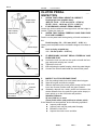
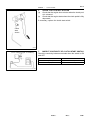
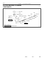
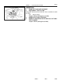
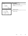
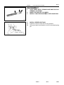
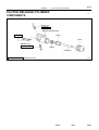
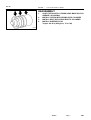
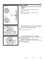
CL–1
CLUTCH
–
TROUBLESHOOTING
TROUBLESHOOTING
CL034–01
PROBLEM SYMPTOMS TABLE
Use the table below to help you find the cause of the problem. The numbers indicate the priority of the likely
cause of the problem. Check each part in order. If necessary, replace these parts.
Symptom
Suspect Area
See page
Clutch grabs/chatters
1. Engine mounting (Loosen)
2. Clutch disc (Runout is excessive)
3. Clutch disc (Oily)
4. Clutch disc (Worn out)
5. Clutch disc torsion rubber (Damaged)
6. Clutch disc (Glazed)
7. Diaphragm spring (Out of tip alignment)
–
CL–17
CL–17
CL–17
CL–17
CL
17
CL–17
CL
17
CL–19
Clutch pedal
edal spongy
s ongy
1. Clutch line (Air in line)
2. Master cylinder cup
cu (Damaged)
3. Release cylinder cup (Damaged)
–
CL–4
CL 4
CL–9
Clutch noisy
1. Release bearing (Worn,
1
(Worn dirty,
dirty or damaged)
2 Clutch
2.
Cl h disc
di torsion
i rubber
bb (Damaged)
(D
d)
CL–19
CL
19
CL 17
CL–17
Cl t h slips
Clutch
li
1. Clutch pedal
edal (Free
(Freeplay
lay out of adjustment)
2. Clutch disc (Oily)
3. Clutch disc (Worn out)
4. Dia
Diaphragm
hragm sspring
ring (Damaged)
5. Pressure plate
late (Distortion)
6. Flywheel (Distortion)
CL–2
CL–17
CL–17
CL
17
CL–17
CL
17
CL–17
CL
17
–
Cl t h does
Clutch
d
nott disengage
di
1. Clutch pedal (Freeplay out of adjustment)
1
2 Clutch line (Air in line)
2.
3 Master cylinder cup (Damaged)
3.
4 Release cylinder cup (Damaged)
4.
5 Clutch disc (out of true)
5.
6 Clutch
6.
Cl tch disc (Runout
(R no t is excessive)
e cessi e)
7 Cl
7.
Clutch
t h di
disc (Li
(Lining
i b
broken)
k )
8 Clutch
8.
Cl t h disc
di (Dirty
(Di t or burned)
b
d)
9. Cl
Clutch
h di
disc (Oil
(Oily))
10. Clutch disc (Lack of spline grease)
11. Diaphragm
g spring
g ((Damaged)
g )
12. Diaphragm
g spring
g (Out
(
of tip alignment)
g
)
13. Pressure plate (Distortion)
CL–2
–
CL 4
CL–4
CL 9
CL–9
CL 17
CL–17
CL 17
CL–17
CL 17
CL–17
CL 17
CL–17
CL
CL–17
CL–19
CL–17
CL–19
CL–17
Author:
Date:
1780
CL–2
CLUTCH
–
CLUTCH PEDAL
CLUTCH PEDAL
CL035–01
INSPECTION
1.
Pedal Height
Adjust Point
Push Rod Play
and Freeplay
Adjust Point
Push Rod Play
Pedal Height
Q10088
CHECK THAT PEDAL HEIGHT IS CORRECT
Pedal height from asphalt sheet:
1MZ–FE: 161.8 – 171.8 mm (6.370 – 6.764 in.)
5S–FE: 156.8 – 166.8 mm (6.173 – 6.567 in.)
2.
IF NECESSARY, ADJUST PEDAL HEIGHT
Loosen the lock nut and turn the stopper bolt until the height is
correct. Tighten the lock nut.
3.
CHECK THAT PEDAL FREEPLAY AND PUSH ROD
PLAY ARE CORRECT
Push in on the pedal until the beginning of clutch resistance is
felt.
Pedal freeplay: 5.0 – 15.0 mm (0.197 – 0.591 in.)
Gently push the pedal until the resistance begins to increase a
little.
Push rod play at pedal top:
1.0 – 5.0 mm (0.039 – 0.197 in.)
4.
(a)
Pedal Freeplay
(b)
(c)
(d)
IF NECESSARY, ADJUST PEDAL FREEPLAY AND
PUSH ROD PLAY
Loosen the lock nut and turn the push rod until the freeplay and push rod play are correct.
Tighten the lock nut.
After adjusting the pedal freeplay, check the pedal height.
Connect the air duct and install the lower finish panel.
CL0042
5.
(a)
(b)
(c)
25 mm (0.98 in. ) or more
Release
Point
Full Stroke
End Position
CL0512
INSPECT CLUTCH RELEASE POINT
Pull the parking brake lever and install wheel stopper.
Start the engine and idle the engine.
Without depressing the clutch pedal, slowly shift the shift
lever into reverse position until the gears contact.
(d) Gradually depress the clutch pedal and measure the
stroke distance from the point the gear noise stops (release point) up to the full stroke end position.
Standard distance:
25 mm (0.98 in.) or more
(From pedal stroke end position to release point)
If the distance not as specified, do the following operation.
Inspect pedal height.
Inspect push rod play and pedal freeplay.
Bleed the clutch line.
Inspect the clutch cover and disc.
Author:
Date:
1781
CL–3
CLUTCH
–
CLUTCH PEDAL
6.
(a)
CHECK CLUTCH START SYSTEM
Check that the engine does not start when the clutch pedal is released.
(b) Check that the engine starts when the clutch pedal is fully
depressed.
If necessary, replace the clutch start switch.
Clutch
Start
Switch
Q00307
5.0 ± 0.5 mm (0.197 ± 0.020 in.)
7.
INSPECT CONTINUITY OF CLUTCH START SWITCH
Check the continuity between terminals when the switch is ON
and OFF.
Switch position
Condition
ON (pushed)
Continuity
OFF (free)
No continuity
CL0477
Author:
Date:
1782
CL–4
CLUTCH
–
CLUTCH MASTER CYLINDER
CLUTCH MASTER CYLINDER
CL036–01
COMPONENTS
Filler Cap
Clip
Float
Reservoir
Tank
Grommet
Clevis Pin
Boot
Slotted Spring Pin
Washer
Master Cylinder Body
Clevis
Piston
Lock Nut
Clutch Line
Snap Ring
15 (155, 11)
Push Rod
Spring
12 (120, 9)
Non–reusable part
N·m (kgf·cm, ft·lbf) : Specified torque
Q10085
Author:
Date:
1783
CL–5
CLUTCH
–
CLUTCH MASTER CYLINDER
CL037–01
REMOVAL
SST
Q10094
1.
DRAW OUT FLUID WITH SYRINGE
2.
DISCONNECT CLUTCH LINE
Using SST, disconnect the clutch line. Use a container to catch
the fluid.
SST 09023–00100
Torque: 15 N·m (155 kgf·cm, 11 ft·lbf)
3.
REMOVE CLIP AND CLEVIS PIN
4.
REMOVE 2 MOUNTING NUTS AND PULL OUT MASTER CYLINDER
Torque: 12 N·m (120 kgf·cm, 9 ft·lbf)
Author:
Date:
1784
CL–6
CLUTCH
–
CLUTCH MASTER CYLINDER
CL038–01
DISASSEMBLY
1.
(a)
(b)
REMOVE RESERVOIR TANK
Using a pin punch and hammer, drive out the slotted
spring pin.
Remove the reservoir tank and grommet.
Q10083
2.
REMOVE PUSH ROD
Pull back the boot, and using snap ring pliers, remove the snap
ring.
3.
REMOVE PISTON
Q05039
Author:
Date:
1785
CL–7
CLUTCH
–
CLUTCH MASTER CYLINDER
CL039–01
REASSEMBLY
1.
2.
3.
COAT PARTS WITH LITHIUM SOAP BASE GLYCOL
GREASE, AS SHOWN
INSERT PISTON INTO CYLINDER
INSTALL PUSH ROD ASSEMBLY WITH SNAP RING
CL0528
4.
(a)
(b)
INSTALL RESERVOIR TANK
Install the reservoir tank and a new grommet.
Using a pin punch and hammer, drive in the slotted spring
pin.
Protrusion
1.5 – 3.5 mm
(0.059 – 0.138 in.)
Q10081
Author:
Date:
1786
CL–8
CLUTCH
–
CLUTCH MASTER CYLINDER
CL03A–01
INSTALLATION
Installation is in the reverse order of removal (See page CL–5).
HINT:
After installation, bleed system and adjust clutch pedal (See page CL–2).
Author:
Date:
1787
CL–9
CLUTCH
–
CLUTCH RELEASE CYLINDER
CLUTCH RELEASE CYLINDER
CL03B–01
COMPONENTS
Clutch Line
15 (155, 11)
Release Cylinder Body
12 (120, 9)
Piston
Boot
Bleeder Plug
8.4 (85, 74 in.·lbf)
Spring
Push Rod
N·m (kgf·cm, ft·lbf) : Specified torque
Q10016
Author:
Date:
1788
CL–10
CLUTCH
–
CLUTCH RELEASE CYLINDER
CL03C–01
REMOVAL
SST
Q10077
1.
DISCONNECT CLUTCH LINE
Using SST, disconnect the line. Use a container to catch the
fluid.
SST 09023–00100
Torque: 15 N·m (155 kgf·cm, 11 ft·lbf)
2.
REMOVE 2 BOLTS AND PULL OUT RELEASE CYLINDER
Torque: 12 N·m (120 kgf·cm, 9 ft·lbf)
Author:
Date:
1789
CL–11
CLUTCH
–
CLUTCH RELEASE CYLINDER
CL03D–01
DISASSEMBLY
1.
REMOVE BLEEDER PLUG
2.
PULL OUT BOOT WITH PUSH ROD
3.
REMOVE PISTON
Blow compressed air into the release cylinder and remove the
piston with spring.
Q05878
Author:
Date:
1790
CL–12
CLUTCH
–
CLUTCH RELEASE CYLINDER
CL03E–01
REASSEMBLY
1.
2.
3.
4.
COAT PISTON WITH LITHIUM SOAP BASE GLYCOL
GREASE, AS SHOWN
INSTALL PISTON WITH SPRING INTO CYLINDER
INSTALL BOOT WITH PUSH ROD TO CYLINDER
INSTALL BLEEDER PLUG
Torque: 8.4 N·m (85 kgf·cm, 74 in.·lbf)
Q06048
Author:
Date:
1791
CL–13
CLUTCH
–
CLUTCH RELEASE CYLINDER
CL03F–01
INSTALLATION
Installation is in the reverse order of removal (See page CL–10).
HINT:
After installation, bleed clutch system.
Author:
Date:
1792
CL–14
CLUTCH
–
CLUTCH ACCUMULATOR (1MZ–FE)
CLUTCH ACCUMULATOR (1MZ–FE)
CL03G–01
COMPONENTS
w/ Cruise Control System :
Starter
39 (400, 29)
Cruise Control
Actuator
21 (210, 15)
Battery
27 (270, 20)
13 (130, 9)
13 (130, 9)
Clutch Accumulator Bracket
15 (155, 11)
N·m (kgf·cm, ft·lbf) : Specified torque
Q10092
Author:
Date:
1793
CL–15
CLUTCH
–
CLUTCH ACCUMULATOR (1MZ–FE)
CL03H–01
REMOVAL
1.
(a)
(b)
w/ Cruise Control System:
REMOVE CRUISE CONTROL ACTUATOR
Remove the battery.
Remove the 3 bolts and cruise control actuator with
bracket.
Torque: 13 N·m (130 kgf·cm, 9 ft·lbf)
Q10074
2.
(a)
(b)
REMOVE STARTER
Remove the nut and disconnect the connectors.
Remove the 2 bolt and clamp.
Torque: 39 N·m (400 kgf·cm, 29 ft·lbf)
3.
(a)
REMOVE CLUTCH ACCUMULATOR WITH BRACKET
Using SST, disconnect the clutch lines from the clutch accumulator.
Torque: 15 N·m (155 kgf·cm, 11 ft·lbf)
SST 09023–00100
Remove the 2 bolts and nut.
Torque:
Bolt: 21 N·m (210 kgf·cm, 15 ft·lbf)
Nut: 27 N·m (270 kgf·cm, 20 ft·lbf)
Q10078
SST
Q10076
(b)
Author:
Date:
1794
CL–16
CLUTCH
–
CLUTCH ACCUMULATOR (1MZ–FE)
CL03I–01
INSTALLATION
Installation is in the reverse order of removal (See page CL–15).
Author:
Date:
1795
CL–17
CLUTCH
–
CLUTCH UNIT
CLUTCH UNIT
CL03J–01
COMPONENTS
5S–FE :
Release Fork
Flywheel
39 (400, 29)
19 (195, 14)
x6
Release Bearing and Hub
Release Fork
47 (480, 35)
5S–FE :
Clutch Disc
Clutch Cover
Clutch Disc
Boot
N·m (kgf·cm, ft·lbf) : Specified torque
Q10017
Author:
Date:
1796
CL–18
CLUTCH
–
CLUTCH UNIT
CL03K–01
REMOVAL
1.
Matchmarks
Q10161
REMOVE TRANSAXLE FROM ENGINE
(See page E153 MX–4, S51 MX–4)
2.
REMOVE CLUTCH COVER AND DISC
(a) Place matchmarks on the flywheel and clutch cover.
(b) Loosen each set bolt one turn at a time until spring tension
is released.
(c) Remove the set bolts, and pull off the clutch cover with the
clutch disc.
NOTICE:
Do not drop the clutch disc.
3.
1MZ–FE:
(a)
(b)
REMOVE RELEASE BEARING AND FORK FROM
TRANSAXLE
Remove the release bearing together with the fork and
then separate them.
Remove the boot.
5S–FE:
Z19000
Author:
Date:
1797
CL–19
CLUTCH
–
CLUTCH UNIT
CL03L–01
INSPECTION
1MZ–FE:
1.
INSPECT CLUTCH DISC FOR WEAR OR DAMAGE
Using calipers, measure the rivet head depth.
Minimum rivet depth: 0.3 mm (0.012 in.)
If necessary, replace the clutch disc.
5S–FE:
Q10090
2.
INSPECT CLUTCH DISC RUNOUT
Using a dial indicator, check the disc runout.
Maximum runout: 0.8 mm (0.031 in.)
If necessary, replace the clutch disc.
CL0373
3.
INSPECT FLYWHEEL RUNOUT
Using a dial indicator, check the flywheel runout.
Maximum runout: 0.1 mm (0.004 in.)
If necessary, replace the flywheel.
CL0372
A
4.
INSPECT DIAPHRAGM SPRING FOR WEAR
Using calipers, measure the diaphragm spring for depth and
width of wear.
Maximum:
Depth A: 0.6 mm (0.024 in.)
Width B: 5.0 mm (0.197 in.)
If necessary, replace the clutch cover.
B
Z09915
Author:
Date:
1798
CL–20
CLUTCH
–
CLUTCH UNIT
5.
INSPECT RELEASE BEARING
Turn the bearing by hand while applying force in the axial direction.
HINT:
The bearing is permanently lubricated and requires no cleaning
or lubrication.
If necessary, replace the bearing.
N00414
Author:
Date:
1799
CL–21
CLUTCH
–
CLUTCH UNIT
CL03M–02
INSTALLATION
1MZ–FE:
1.
(a)
(b)
SST
INSTALL CLUTCH DISC AND CLUTCH COVER ON
FLYWHEEL
1MZ–FE:
Insert SST in the clutch disc, and then set them.
SST 09301–00220
5S–FE:
Insert SST in the clutch disc, and then set them.
SST 09301–00210
Flywheel
Side
5S–FE:
SST
Q10089
3
5
(c)
(d)
SST
1
Align the matchmarks on the clutch cover and flywheel.
Torque the bolts on the clutch cover in the order shown.
Torque: 19 N·m (195 kgf·cm, 14 ft·lbf)
HINT:
Temporarily tighten the No.3 bolt.
6
4
2
Matchmarks
Q10084
2.
CHECK DIAPHRAGM SPRING TIP ALIGNMENT
Using a dial indicator with roller instrument, check the diaphragm spring tip alignment.
Maximum non–alignment: 0.5 mm (0.020 in.)
If alignment is not as specified, using SST, adjust the diaphragm spring tip alignment.
SST 09333–00013
SST
Q10072
Author:
Date:
1800
CL–22
CLUTCH
3.
1MZ–FE Engine:
(a)
(b)
–
CLUTCH UNIT
APPLY MOLYBDENUM DISULPHIDE LITHIUM BASE
GREASE (NLGI NO.2)
Apply release hub grease to these parts:
Release fork and hub contact point
Release fork and push rod contact point
Release fork pivot point
Apply clutch spline grease:
Clutch disc spline
HINT:
Recommended grease part number 08887–01706 (100 g).
4.
INSTALL RELEASE BEARING AND FORK TO TRANSAXLE
Install the bearing to the release fork, and then install them to
the transaxle.
5.
INSTALL TRANSAXLE TO ENGINE
(See page E153 MX–9, S51 MX–8)
5S–FE Engine:
Q10091
Author:
Date:
1801