1
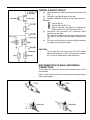
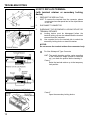
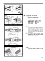
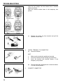
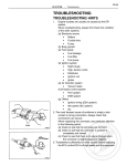
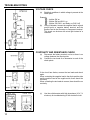
TROUBLESHOOTING
VOLTAGE CHECK
(a)
Establish conditions in which voltage is present at the
check point.
Example:
(b)
– Ignition SW on
– Ignition SW and SW 1 on
– Ignition SW, SW 1 and Relay on (SW 2 off)
Using a voltmeter, connect the negative lead to a good
ground point or negative battery terminal, and the
positive lead to the connector or component terminal.
This check can be done with a test light instead of a
voltmeter.
CONTINUITY AND RESISTANCE CHECK
(a)
(b)
Disconnect the battery terminal or wire so there is no
voltage between the check points.
Contact the two leads of an ohmmeter to each of the
check points.
If the circuit has diodes, reverse the two leads and check
again.
When contacting the negative lead to the diode positive side
and the positive lead to the negative side, there should be
continuity.
When contacting the two leads in reverse, there should be no
continuity.
(c)
10
Use the volt/ohmmeter with high impedance (10 kΩ/V
minimum) for troubleshooting of the electrical circuit.
FINDING A SHORT CIRCUIT
(a)
Remove the blown fuse and disconnect all loads of the
fuse.
(b) Connect a test light in place of the fuse.
(c) Establish conditions in which the test light comes on.
Example:
– Ignition SW on
– Ignition SW and SW 1 on
– Ignition SW, SW 1 and Relay on (Connect the
Relay) and SW 2 off (or Disconnect SW 2)
(d) Disconnect and reconnect the connectors while
watching the test light.
The short lies between the connector where the test
light stays lit and the connector where the light goes
out.
(e) Find the exact location of the short by lightly shaking
the problem wire along the body.
CAUTION:
Do not open the cover or the case of the ECU unless
absolutely necessary. (If the IC terminals are touched,
the IC may be destroyed by static electricity.)
DISCONNECTION OF MALE AND FEMALE
CONNECTORS
To pull apart the connectors, pull on the connector itself, not the
wire harness.
HINT: Check to see what kind of connector you are disconnecting
before pulling apart.
11
TROUBLESHOOTING
HOW TO REPLACE TERMINAL
(with terminal retainer or secondary locking
device)
1.
PREPARE THE SPECIAL TOOL
HINT: To remove the terminal from the connector, please
construct and use the special tool or like object shown
on the left.
2.
DISCONNECT CONNECTOR
3.
DISENGAGE THE SECONDARY LOCKING DEVICE OR
TERMINAL RETAINER.
(a) Locking device must be disengaged before the
terminal locking clip can be released and the terminal
removed from the connector.
(b) Use a special tool or the terminal pick to unlock the
secondary locking device or terminal retainer.
NOTICE:
Do not remove the terminal retainer from connector body.
For Non–Waterproof Type Connector
HINT: The needle insertion position varies according
to the connector’s shape (number of terminals
etc.), so check the position before inserting it.
“Case 1”
Raise the terminal retainer up to the temporary
lock position.
“Case 2”
Open the secondary locking device.
12
For Waterproof Type Connector
HINT: Terminal retainer color is
according to connector body.
different
Example:
Terminal Retainer: Connector Body
Black or White : Gray
Black or White : Dark Gray
Gray or White
: Black
“Case 1”
Type where terminal retainer is pulled up
to the temporary lock position (Pull Type).
Insert the special tool into the terminal
retainer access hole ( Mark) and pull
the terminal retainer up to the temporary
lock position.
HINT: The needle insertion position varies
according to the connector’s shape
(Number of terminals etc.), so check the
position before inserting it.
“Case 2”
Type which cannot be pulled as far as
Power Lock.
13
TROUBLESHOOTING
Insert the tool straight into the access hole of terminal
retainer as shown.
Push the terminal retainer down to the temporary lock
position.
(c)
4.
Release the locking lug from terminal and pull the
terminal out from rear.
INSTALL TERMINAL TO CONNECTOR
(a) Insert the terminal.
HINT:
1.
Make sure the terminal is positioned correctly.
2.
Insert the terminal until the locking lug locks firmly.
3.
Insert the terminal with terminal retainer in the
temporary lock position.
(b)
5.
14
Push the secondary locking device or terminal retainer
in to the full lock position.
CONNECT CONNECTOR