1
RT1
Real Time Spectrum Analyser
Preliminary
Operating Instructions
XTA Electronics Ltd.
Riverside Business Centre,
Worcester Road,
Stourport-on-Severn,
Worcs. DY11 9BZ.
England
Tel : 01299 879977 (Intl. +44 1299 879977)
Fax: 01299 879969 (Intl. +44 1299 879969)
USA Distribution:
Group One Ltd.
80, Sea Lane,
Farmingdale,
N.Y. 11735
U.S.A.
Tel: (516) 249-1399
Fax: (516) 753-1020
© XTA Electronics Ltd 17/10/94
Contents.
Introduction ............................................................................................
1
Features ...................................................................................................
1
Front Panel Functions ..............................................................................
3
Rear Panel Functions ...............................................................................
4
Basic RTA Mode .....................................................................................
5
A Weighting ..............................................................................................
6
SPL Relative ............................................................................................
6
SLM Modes ..............................................................................................
6
Memory Store ...........................................................................................
7
Memory Accumulate .................................................................................
8
Memory Recall .........................................................................................
8
Memory Compare .....................................................................................
9
Real Time Compare .................................................................................
9
Time Level Mode .....................................................................................
10
RT60 Mode Introduction ........................................................................
10
RT60 Default Mode ..................................................................................
11
RT60 Measurement Mode ........................................................................
11
Sweep Mode ...........................................................................................
12
Output Mode ............................................................................................
13
Sweep Start Frequency ............................................................................
13
Sweep End Frequency ..............................................................................
13
Unit set-up Menu Options .........................................................................
14
Using an External Printer ..........................................................................
14
Specifications ...........................................................................................
15
Warranty ..................................................................................................
16
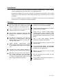
Introduction
The RT1 Real Time Spectrum Analyser represents a breakthrough in audio analysis,
offering capabilities far beyond the reach of conventional devices.
Operational simplicity has not been sacrificed to implement this flexibility, with intuitive
controls and a clear menu-driven LCD display allowing quick measurements to be made
confidently.
The RT1 combines rugged construction for reliability on the road with the performance
needed for the most demanding consultancy project.
Features
Powerful analysis tool combining 1/3 octave
RTA, SPL meter, RT60 analysis and a swept
frequency analyser in one unique product.
Fully controllable pink noise and sine wave
oscillator output sources included.
Independently selectable 'A' weighting filters
for both 1/3 octave and SLM displays.
Crystal locked switched capacitor 1/3 octave
filters for long term stability.
RTA features simultaneous Bar and Peak
displays with separately adjustable time
constants.
Printer port for directly driving industry
standard printers, allows permanent copies
of any display curve to be made, with user
selectable title and automatic time and date
stamp.
Accurate RT60 measurement, using internally
gated noise or external source. Auto and
manual window functions for direct RT60
measurement (result).
Time / Level mode displays historical
information on peak levels attained.
Swept analysis measurements using
tracking filters, allow narrow band problems
to be identified and plotted via the printer
port.
Accurate SPL meter displays absolute or
relative SPL, with average or peak response.
Both RT60 and RTA modes each have 32
non volatile memories with accumulate
function. The RTA memories allow memory
to memory compare and memory to real
time compare (difference) functions.
Mic and Line inputs with mic inputs on front
and rear panel.
The LED bar graph display has selectable
average and peak response with switchable
resolution of 1 or 2dB per LED.
Manual and Auto range control of input
attenuator setting.
RS 232 computer port provided. RS 422
option available.
A high quality measurement microphone is
included with each unit.
RT1 Page 1
Thanks
Thank you for choosing the XTA RT1 for your application. Please spare a little time to digest
the contents of this manual (figuratively speaking), so that you obtain the best possible
performance from this unit.
All XTA products are carefully engineered for world class performance and reliability.
If you would like further information on this or any other XTA product, please call us.
We look forward to helping in the near future.
XTA Electronics Ltd.
Safety Warnings
Please note the following information which is provided for your safety:
Check correct operating voltage is set on the power supply before connecting mains power.
Do not expose this unit to rain or moisture.
Do not expose this unit to excessive heat.
Replace all fuses with correct type only.
Do not remove the covers from this unit. No user serviceable parts inside - refer all servicing to
qualified personnel.
The mains power cord to the power supply is fitted with a safety earth (ground) connection.
Do not operate this unit with this connection removed.
Unpacking the RT1
After unpacking the unit please check carefully for damage. If damage is found, please
notify the carrier concerned at once. Any claim must be instigated by you, the consignee.
Please retain all packaging in case of future reshipment.
RT1 Page 2
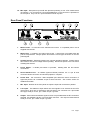
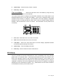
Front Panel Functions
2
1
8
3
10
7
11 13
RT1 REAL TIME SPECTRUM ANALYSER
MENU / OPTIONS
RESOLUTION
AV PK
MIC
LINE
MICROPHONE
2dB
1dB
100spl
+6/+12
92.3spl
+6/+12
DECAY:BAR=2 PK=2
+3/+6
+3/+6
REF-dB
RT60
SW`P
REF-dB
-3/-6
-3/-6
MODE
FREEZE
QUIT
PRINT
AUTO
16K
10K
20K
12K5
4K
8K
5K
6K3
2K
2K5
3K15
1K
1K6
800
1K25
315
500
400
630
250
200
80
125
100
160
31
63
25
50
-6/-12
40
-6/-12
MENU
LEVEL
ENTER
RANGE
[REF+10dB]
4
5
6
9
12 14
15
1.
Main RTA Display - Displays power level at 30 one third octave centre frequencies
25Hz to 20kHz. Display range is switchable to ±7dB / ±14dB about the centre reference
point.
2.
Level - Displays the overall level at audio frequencies. This level is 10dB greater than
shown on the panel calibration.
3.
LCD Display - Shows menu options and various parameters dependant on the menu
selection. See operating section for detailed information.
4.
Menu - Allows menu functions to be previewed on the LCD display.
5.
Option Keys - Adjust parameters and options. See operating section for detailed
information. Also allows up/down control of menu selection when previewing menu.
6.
Enter - Confirms the chosen menu option and enters this as the working mode.
7.
Resolution - Selects the RTA display resolution to 1 or 2dB per LED.
8.
Mode - Selects between the three basic operating modes for the RT1
RTA
= No LED's light .
RT60
= RT60 LED lights.
Sweep = SW'P LED lights.
9.
Quit - Returns unit to basic default operating mode from existing menu selection.
10. Response - Selects average or peak response measurements for the main RTA
display.
11. Freeze - 'Holds' RTA and SLM measurements. The LED flashes until the 'freeze'
function is cancelled by pressing the 'freeze' key again.
12. Print - Holds display and prints current display information. If no printer is connected
"No Printer" is displayed on the LCD display. See 'Printer' section for detailed
information.
13. Mic/Line - Selects mic or line input sources via independent XLR connectors.
14. Range Keys - Set the operating reference for the RTA in 7 ranges from -50dBu to
+10dBu, with line source selected or 50spl to 110spl with microphone source selected.
Pressing both keys together selects 'auto-range' mode and lights the 'auto' LED.
RT1 Page 3
15. Mic Input - Microphone input XLR with phantom powering to suit XTA measurement
microphone. For convenience a second paralleled mic. input connector is provided on
the rear panel. Only one mic. input should be used at any time.
Rear Panel Functions
1.
Mains Power - is connected via a standard IEC socket. A compatible power cord is
supplied with the unit.
2.
Mains Fuse - is located in the mains inlet socket. A spare fuse is provided within the
pull-out compartment. Always replace fuse with the correct type as shown on the rear
panel legend.
3.
Voltage Selector - Switches between two nominal operating voltages. Please ensure
this is set for the correct voltage before operating. Disconnect power to the unit before
resetting this selector.
4.
Power Switch - a double pole switch is provided,
connections.
5.
Serial Interface Port - An RS232 (optional RS422) interface via a 9 pin D shell
connector allows connection of external equipment / computer.
6.
Printer Port - this centronics / IBM compatible port allows the direct connection of
approved printers via a standard 25 pin D shell connector. See 'Printer' section for
detailed information.
7.
Mic. Input - identical to the front panel microphone input and connected in parallel.
8.
Line Input - This balanced input allows line level signals to be selected as the RTA
input source, when 'line' is selected on the front panel. The connector is a 3 pin female
XLR type, wired pin 2 'Hot', pin 3 'Cold' and pin 1 ground.
9.
Output - Pink noise and oscillator signal sources are provided within the RT1 and when
selected, are available via this 3 pin male XLR connector. The output is balanced and
wired pin 2 'Hot', pin 3 'Cold' and pin 1 ground.
isolating both live and neutral
RT1 Page 4
10. Output Level - Controls the level of the output signal between 'off' and +6dB.
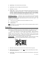
Operating the RT1
Basic RTA Mode.
This is the default mode for the unit and can be accessed at
any time by pressing 'Quit.', assuming RTA is selected on the 'Mode' key.
1.
Ref. Level - Shows the current reference level as selected via the range keys. The
display reads dBu when line input is selected and spl for mic. input. Note: with 'A'
weighting filter selected display shows dBA / spA.
2.
SLM - Sound pressure meter readout, calibrated in dBu for line input and spl for mic.
input. Note: (a) with 'A' weighting filter selected display shows dBA / spA. (b) with spl
relative selected, display shows dBr.
3.
Bar Decay - Shows decay time for RTA bar (column) display.
4.
Peak Decay - Shows decay time for RTA peak hold display.
5.
Option Key 1 - Adjusts Bar decay time from '0' (off) to '5' (slow). '0' position is not
available when peak hold decay is set at '0' (off).
6.
Option Key 2 - Adjusts Peak hold decay time from '0' (off) to '%' (infinite hold). '0'
position is not available when bar decay is set at '0'.
7.
Enter Key - Not used
Notes: The following additional options are available in this mode, using the appropriate
menu selection.
(i)
'A' weighting filters on / off for sound level meter.
(ii)
'A' weighting filters on / off for main RTA display.
(iii)
SPL relative. i.e. SLM displays difference in dB from a pre-set reference level.
(iiii)
SLM mode can be set for Average or Peak reading with a choice of times.
RT1 Page 5
RTA Menu Options
'A' weighting
Press menu and select 'A' weighting by using menu key or option
keys. Press 'Enter' to load selection.
1.
Ref. Level - Shows Ref. level as in basic RTA mode.
2.
SLM - Shows SLM readout as in basic RTA mode.
3.
RTA Status - Shows 'A' weighting filter status for main RTA display (Yes / No).
4.
SLM Status - Shows 'A' weighting filter status for SLM readout (Yes / No).
5.
Option Key 1 - Selects 'A' weighting Status for main display.
6.
Option Key 2 - Selects 'A' weighting Status for SLM readout.
7.
Enter Key - Not used.
SPL Relative.
Press menu and select 'SPL Relative' by using menu key or option
keys. Press 'Enter' to load selection.
1.
Ref. Level - Shows Ref. level as in basic RTA mode.
2.
SLM - Shows SLM readout as in basic RTA mode.
3.
Ref. Level - Shows current reference level in dB, or [OFF] if SLM Rel. Option is not
selected.
4.
Option Keys - Sets reference level for SLM.
5.
Enter Key - Toggles SLM relative mode on / off.
RT1 Page 6
SLM Modes
Press menu and select 'SLM Modes' by using menu key or option
keys. Press 'Enter' to load selection.
1.
Ref. Level - Shows Ref. level as in basic RTA mode.
2.
SLM - Shows SLM readout as in basic RTA mode.
3.
SLM Mode - Displays current SLM mode, Average (AVG.) or Peak reading.
4.
Response - Displays response time for SLM; instantaneous (INST.), 1 Sec, or 8
Secs.
5.
Option Key 1 - Selects SLM mode.
6.
Option Key 2 - Selects SLM response time.
7.
Enter Key - Not used.
Memory Store.
Press menu and select 'Memory Store' by using menu key or option
keys. Press 'Enter' to load selection.
1.
Ref. Level - Shows Ref. level as in basic RTA mode.
2.
SLM - Shows SLM readout as in basic RTA mode.
3.
Mem No. - Shows memory number selected via option keys. '?' after the number
identifies a memory previously used.
4.
Option Keys - Selects memory location number from 1 to 32.
5.
Enter Key - Loads current display information into memory currently selected.
RT1 Page 7
Memory Accumulate.
Press menu and select 'Memory Accum.' by using menu key
or option keys. Press 'Enter' to load selection.
1.
Ref. Level - Shows Ref. level as in basic RTA mode.
2.
SLM - Shows SLM readout as in basic RTA mode.
3.
Mem No. - Shows memory number selected via option keys.
4.
Accumulations. - Shows the number of accumulations made into the current memory
location.
5.
Option Keys - Selects memory location number from 1 to 32.
6.
Enter Key - Adds present information to any previous accumulation loaded into the
current memory location.
Note: If new measurements are to be accumulated into a memory location that has previous
accumulations i.e. 4. above displays [1] or more, The memory must be, in effect, erased by
storing the first measurement using the 'Memory Store' function then using the memory
accumulate function for subsequent 'additions'.
Memory Recall.
Press menu and select 'Memory Recall.' by using menu key or option
keys. Press 'Enter' to load selection.
1.
Ref. Level - Shows Ref. level as in basic RTA mode.
2.
SLM - Shows SLM readout as in basic RTA mode.
3.
Mem No. - Shows memory number selected via option keys.
4.
Accumulations. - Shows the number of accumulations made into the current memory
location.
5.
Option Keys - Selects memory location number from 1 to 32.
RT1 Page 8
6.
Enter Key - Not used.
Memory Compare.
Press menu and select 'Memory Compare.' by using menu
key or option keys. Press 'Enter' to load selection.
This function allows the information in two memories to be compared, and the resultant
difference curve to shown on the main RTA display.
1.
Ref. Level - Shows Ref. level as in basic RTA mode.
2.
SLM - Shows SLM readout as in basic RTA mode.
3.
Ref.Mem No. - Shows the reference memory number, as selected via option keys.
4.
Comp.Mem No. - Shows the memory number for the information to be compared with
the reference.
5.
Option Keys - Selects memory location number for Ref.Mem. or Comp.Mem (see
below).
6.
Enter Key - Toggles 'option key 'control between Ref.Mem No. and Comp.Mem No.
Real Time Compare.
Press menu and select 'Real Time Compare.' by using menu
key or option keys. Press 'Enter' to load selection.
This function allows real time measurements to be compared with information stored in a
memory. The resultant difference curve to shown on the main RTA display.
1.
Ref. Level - Shows Ref. level as in basic RTA mode.
2.
SLM - Shows SLM readout as in basic RTA mode.
3.
Mem No. - Shows the memory number selected as the reference via option keys.
4.
Accumulations. - Shows the number of accumulations in the current memory location.
RT1 Page 9
5.
Option Keys - Selects memory number required.
6.
Enter Key - Not used.
Time Level Mode.
Press menu and select 'Time Level Mode' by using menu key
or option keys. Press 'Enter' to load selection.
This option allows peak or average level information obtained via the SLM section to be
displayed against time on the main RTA display. In this way an historical picture of the
maximum levels reached is obtained. The 'time-base' of the RTA display is adjustable
between 62.5mS and 256 seconds per LED column, giving a maximum display period of
between 1.875 seconds and 2 hours 13 minutes. This information can be printed in the
normal way.
1.
Ref. Level - Shows Ref. level as in basic RTA mode.
2.
SLM - Shows SLM readout as in basic RTA mode.
3.
Time Base. - Shows the current time base of the RTA display, adjustable between
62.5mS and 256 seconds per LED column.
4.
Option Keys - Sets RTA display time base.
5.
Enter Key - Press to initiate time level measurement.
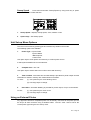
RT60 Mode
The RT1 provides for accurate measurement of RT60 reverberation time using internally
gated noise or an external source. Auto and manual window functions are provided. RT60
decay curve (window) is shown on the main RTA display and the RT60 time is shown on the
LCD screen. Measurements can be taken at any octave centre frequency 31Hz to 16kHz or
'wideband'. The decay curve can be expanded on the RTA screen, if required, to aid manual
adjustments of the measurement 'window' . RT60 measurements can be stored, recalled or
accumulated into memory as in the RTA mode.
RT1 Page 10
RT60 Default Mode.
Press mode key until RT60 LED lights. Pressing Quit whilst in
RT60 mode will always return the unit to this default mode.
1.
Ref. Level - Shows the current reference level as selected via the range keys.
2.
SLM - Shows level for line or mic. input.
3.
Frequency - Shows RT60 centre frequency as selected by option keys. Note 'O/LEV'
indicates wideband measurements. If a signal is present the centre frequency and level
will show on the RTA display.
4.
Option Keys - Selects RT60 centre frequency.
5.
Enter Key - Gates output 'off' and initiates RT60 measurement.
measurement is complete the unit will enter 'measurement mode'.
6.
Quit Key - Selects 'measurement mode' to display last measurement.
When the
RT60 Measurement Mode.
1.
Frequency - Shows RT60 centre frequency used for the measurement.
2.
RT60 Time - Shows the RT60 time calculated by the RT1.
3.
Window Status - Shows the measurement window status as set by option key 1.
Auto - for automatic RT60 calculations.
Start - to manually edit window start point.
End - to manually edit window end point.
4.
RTA Display Time - Shows the full scale horizontal axis time period for the RTA
display. This can be adjusted via option key 2, to expand the displayed decay curve.
Note: Display time =60mS = 2mS per LED column.
120mS=4mS per LED column etc.
RT1 Page 11
5.
Option Key 1 - Sets measurement window status.
6.
Option Key 2 - Sets RTA display horizontal time period.
7.
Enter Key - Not used.
8.
Range Keys - These are used to adjust measurement window start and end points,
dependant on the status set by option key 1. The 'auto' LED will flash when these keys
are active. Adjustments made using these keys will be shown on the main RTA display,
with 'solid' columns representing the new measurement window. The recalculated
RT60 time, based on this new window, will be displayed in the LCD window.
RT60 Menu Options.
Pressing the menu key and using the two option keys allows
all RT60 menu options to be previewed and loaded if required via the enter key. Operating
procedures are identical to those discussed previously for the RTA menu options. The
following options are available:(i)
Store to memory. (an additional 32 memories available for RT60 only).
(ii)
Accumulate to memory.
(iii)
Memory Recall.
Note to manually edit a recalled memory, press the enter key following memory recall, to
make it the 'current' decay curve.
Sweep Mode
The provision of sweepable sine wave and band limited pink noise output sources, together
with tracking filters for input measurements, further extends the capabilities of the RT1.
Start and end frequencies and sweep speed are adjustable. Manual adjustment
("nudging") of centre frequency is also possible allowing problem frequencies to be
identified, using the SLM readout. Although the RTA display has only one third octave
resolution, using the external printer, or simply the SLM meter reading allows the full one
twelfth octave resolution to be realised above 63Hz (1/6 octave below).
Sweep Ready
Press mode key until SW'P LED lights. Pressing Quit whilst in sweep
mode will always return the unit to this default mode (unless a sweep is in progress).
1.
Ref. Level - Shows the current reference level as selected via the range keys.
2.
SLM - Shows level for line or mic. input. Note a low (off scale) reading may be shown
since outputs are gated off.
3.
Option Keys - Allow manual setting of measurement centre frequency. (Not used for
'auto' sweeps).
RT1 Page 12
4.
Enter Key - Gates output 'on' and initiates sweep after a wait period. Sweep
parameters are as previously set via the sweep menu. The LCD display now shows the
measurement centre frequency. As discussed previously, manual adjustments can be
implemented at any time via the option keys.
Sweep Menu Options
Output Mode
Press menu and select 'Output Mode.' by using menu key or option
keys. Press 'Enter' to load selection.
1.
Output mode - Displays current output mode.
(i) B-W Pink Noise - Band limited Pink Noise.
(ii) Sine wave.
2.
Option Keys - Toggle between the two output modes.
Sweep Start Frequency Press menu and select 'Sweep start freq.' by using menu key
or option keys. Press 'Enter' to load selection.
1.
Start Frequency - Shows the current sweep start frequency.
2.
Option Keys - Set Sweep start frequency.
Sweep End Frequency Press menu and select 'Sweep End freq.' by using menu key
or option keys. Press 'Enter' to load selection. This option operates as 'Start Frequency'
above.
RT1 Page 13
Sweep Speed
Press menu and select 'Sweep Speed' by using menu key or option
keys. Press 'Enter' to load selection.
1.
Sweep Speed - Displays sweep speed; slow, medium or fast.
2.
Option Keys - Set Sweep speed.
Unit Set-up Menu Options
This menu is accessed by pressing quit and mic/line keys whilst in RTA mode.
The following options are available.
1.
Printer Type = Epson FX80
Epson LQ850
IBM Proprinter
Canon BJ10
Use option keys to view options and enter key to confirm printer choice.
A start symbol identifies the current selection.
2.
Computer Port = On / Off.
Use option keys to select status and confirm choice with enter key.
3.
Time and Date - Automatic time and date stamp is provided for printer output and this
information is stored in memory with measurement information.
To reset:-
(i). Use option keys to move flashing cursor.
(ii). Use range keys to change.
4.
User Name - Automatic labelling is provided for printer output, of up to 16 characters.
To Set:-
(i). Use option keys to move cursor.
(ii). Use range keys to change.
Using an External Printer
Any approved centronics compatible printer can be directly connected to the printer port via
the 25 pin D shell connector using a standard cable. The RT1 must first be set for the
correct printer type using the Unit set up menu.
RT1 Page 14
With the printer then connected, any current measurement or recalled memory can be
printed by simply pressing the 'Print' key. Problems such as lack of paper (or printer!) are
described on the LCD window.
Automatic Time / Date and Name labelling is provided.
section for more information.
See 'Unit Set up menu'
Specifications
1/3 Octave Display
Preamplifier / Attenuator
Number:
30 x 1/3 octave band pass filters
Line impedance: > 10kohms
ANSI Type E Class 2. Relative filter
Mic. impedance: > 5kohms
flatness ±0.8dB.
Bandwidth:
1 x Overall level (20-20kHz) ±0.5dB.
Weighting:
'A' or 'flat' filters.
Time constants: 10 user selectable.
Display range:
attenuator setting.
Memories
Number
Mic. phantom
power:
15VDC
Ranges:
6 in 10dB steps. Ref=+10dBu to
±7dB in 1dB resolution, ±14dB in
2dB resolution, relative to input
32
addressable
non
volatile
memories with 40 actual stores,
-40dBu (110spl to 60spl)
Output
Number:
1 electronically balanced (gateable).
Impedance:
< 60ohms source.
Level:
Adjustable (+6dBu max.) via rear
panel control.
allowing true accumulation method,
for both RTA and RT60 modes.
Modes:
(25-20kHz).
Response
Fast, 1Sec. and 8 Sec. peak or
average reading.
Range:
Full bandwidth pink noise, 1 octave
band-limited pink noise, sine wave
Sound Level Meter
modes:
20-20kHz ±0.5dB
Ports
Printer:
shell connector.
54spl to 130spl. Referenced to
93.8spl=15mV rms. (Mic input), in 6
Centronics compatible via 25 pin D
Computer:
RS 232 standard (optional RS 422)
via 9 pin D shell connector
x 10dB ranges
4 digit LCD with overload and
Power Requirements
underange indication.
Consumption:
<40 VA
Display modes:
continuous or hold.
Voltage:
110 / 220V ±15% @ 50/60Hz
Weighting:
'A' or 'flat' filters.
Physical
Readout::
Size:
Frequency
response:
3.5"(2U) * 19" * 11.5" (88mm *
482mm
20-20kHz ±0.6dB
*
290mm)
excluding
connectors.
Meets requirements of IEC 651-1979
Weight:
6.2kg Net ( 8.2kg Shipping)
RT1 Page 15
Warranty
This product is warranted against defects in components and workmanship only, for a period
of one year from the date of shipment to the end user. During the warranty period, XTA will,
at it's option, either repair or replace products which prove to be defective, provided that
the product is returned, shipping prepaid, to an authorised XTA service facility.
Defects caused by unauthorised modifications, misuse, negligence, act of God or
accident, or any use of this product that is not in accordance with the instructions provided
by XTA, are not covered by this warranty.
This warranty is exclusive and no other warranty is expressed or implied. XTA is not liable
for consequential damages.
RT1 Page 16