1
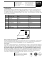
Operating
Instructions
RTK Instruments Limited
St James Business Park,
Knaresborough, North Yorkshire,
England. HG5 8PJ
Telephone: +44 (0)1423 580500
Facsimile: +44 (0)1423 580501
Web: www.rtkinstruments.com
Email: enquiry@ rtkinstruments.com
PPM4 Programmable Process Meter
Description
The PPM4 has been designed and manufactured to the highest standards using the latest surface mount and
micro-controller techniques to provide a fully scalable instrument at a price to match factory-set units. The PPM4 is
easy to use and will give many years of reliable performance.
The process input version of the PPM4 can take both mA (±20mA) and mV inputs (±100mV), link selectable. If the
mA input is used, the mV input may be used as a status input, adding either a tare or hold function (as selected by
the configuration links). Other input types can be accommodated by use of Input Range Extension modules.
To ensure that the PPM4 is installed and operated correctly, please read these instructions thoroughly before use.
If you have any questions with the installation or use of the PPM4, please telephone Technical Sales at RTK
Instruments Ltd on 01423 580500.
Installation
The PPM4 is designed for panel mounting in a DIN standard cut-out of 92mm (+0/-0.5) x 44mm (+0/-1.0) with a
maximum panel thickness of 2.5mm. If the instrument is to be sealed to the panel, a PPM4 unit to panel seal must
be fitted (Part No PPM4GAS). Insert the PPM4 into the panel from the front then slide the metal retaining clips
over the studs on each side of the instrument until they latch in place.
Connection Details
All connections to the PPM4 are shown on the top of the instrument. This label also shows the power supply
voltage, input type and the options fitted. Ensure that this is correct before connecting the instrument. The plug-in
terminals supplied with the PPM4 are high quality and will accept either single core or stranded wire up to 2.5mm2.
Power supply connections
Connect to terminals 1 and 2. The PPM4 is double insulated and does not require an earth connection.
mA input
Connect to terminals 9 (+) and 10 (-)
mV input
Connect to terminals 8 (+) and 10 (-)
Status input connections
To activate the status input, link rear terminals 8 and 10. This is only available if the mA option is used.
Alarm relay connections
Relay common on terminal 3, N/C on 4 and N/O on 5. Ensure that suppressors are fitted to relay contacts when
switching inductive loads.
Transducer supply
Connect to terminals 6 (+) and 7 (-)
Rev 2
Manufacturers of
Alarm Annunciators and Systems | Sequential Event
Recorders | Display Facias | Hazardous Area Interface,
Alarm and Display Products | Signal Conditioning &
Trip Amplifiers | Process Instrumentation
Certificate No. FM14290
ISO9001:2000
RTK Instruments Limited
St James Business Park,
Knaresborough, North Yorkshire,
England. HG5 8PJ
Telephone: +44 (0)1423 580500
Facsimile: +44 (0)1423 580501
Web: www.rtkinstruments.com
Email: enquiry@ rtkinstruments.com
Specification
GENERAL
INPUTS
-20mA to 20mA
-100mV to 100mV
Accuracy
0.1% +/- 1 digit
Other inputs must use the Range Extension module
Input impedance
20mA
< 5Ω
100mV > 1MΩ
Stability
< 250ppm
CMRR
> 120dB
SMMR
> 60dB at 50Hz and 60Hz
OUTPUTS
Alarm relay (optional)
One changeover contact rated at 2A 230V AC
Alarm LED
High brightness red LED
A to D Converter
Dual slope conversion
ADC update rate
5 updates per second
Transducer supply
5, 10 or 24V DC fitted as standard
DISPLAY
Display type
4 digit red 14.2mm high brightness LED
ENVIRONMENT
RFI standards
Designed to exceed EN50081 Pt1 & 2 and EN50082
Pt1 & 2
Electrical standards
Designed to exceed IEC348, IEC1010
Display range
-1999 to 9999
Display update
2 updates per second
Ambient temperature
Storage
-10 to 70oC
SUPPLY
Ambient humidity
0-90% non-condensing
Front Sealing
IP65
Mains version
115V AC +/-10% 50/60Hz
230V AC +/-10% 50/60Hz
Isolated to 500V peak
Size and weight
1/8 DIN, 450g
Low voltage version
10 to 30V DC (or 10 to 24V AC)
Dimensions
48 x 96 x 80mm (W x H x D)
Connections
Plug-in screw terminals to suit maximum cable size of
2.5mm2
Manufacturers of
Alarm Annunciators and Systems | Sequential Event
Recorders | Display Facias | Hazardous Area Interface,
Alarm and Display Products | Signal Conditioning &
Trip Amplifiers | Process Instrumentation
Certificate No. FM14290
ISO9001:2000
RTK Instruments Limited
St James Business Park,
Knaresborough, North Yorkshire,
England. HG5 8PJ
Telephone: +44 (0)1423 580500
Facsimile: +44 (0)1423 580501
Web: www.rtkinstruments.com
Email: enquiry@ rtkinstruments.com
Configuration
The PPM4 configuration links are located behind the removable front panel. The links are read at power on and
whenever a key is pressed. If a key is pressed and any link other than link 1, 2 or 3 (the edit function links) has
been added or removed then the instrument will reset when the edit (or view) function has been completed - this
reset will ensure that the instrument functions as per the links selected. Please refer to Figure 1 and Table 1 below
on how to configure your PPM4.
LK
Option to select
JUMPER OUT
JUMPER IN
1
Decimal point edit
Disable
Enable
2
Cal low edit
Disable
Enable
3
Cal high edit
Disable
Enable
4
Alarm type
Rising/Hi
Falling/Lo
5
Keyboard disable
KB enable
KB disable
6
Status input function
Tare
Hold
7
Hysteresis
On (See Table 2)
Off (See Table 2)
8
Input type
mA
mV
9
Alarm LED action
LED is on when relay energised
LED is off when relay is energised
Table 1: Configuration links
LK1-4
LK5-8
LK9
LED1
Figure 1
Editing and Viewing System Parameters
For normal operation of the PPM4, links 1, 2 and 3 should all be removed. In this configuration, the alarm setpoint
may be viewed or edited using the front panel keys but access to the user scaling and decimal point position is
prevented. Please make sure that the keyboard disable link (LK5) is not fitted during set-up.
Alarm setpoint
Press either key to briefly display the letters SP and then the alarm setpoint. The alarm setpoint will be displayed
until the key is released, when the setpoint value will flash and then the normal measured value will be displayed.
To edit the alarm setpoint, press both keys together. The letters SP will be briefly displayed and then the current
alarm setpoint. Keep both keys depressed and the right most digit will begin flashing. If this digit is correct and
does not require changing, then both keys may now be released. If the first digit requires editing, keep the up or
down key pressed, and after a short pause this flashing digit will display of the measured value.begin to change.
Wait until a digit to be modified is flashing and use the up and down arrows to edit the digit. When no keys are
pressed for a short period of time the flashing digit will move to the left. When the edit is completed, the new
setpoint will flash and then the instrument will return to the display of the measured value.
Manufacturers of
Alarm Annunciators and Systems | Sequential Event
Recorders | Display Facias | Hazardous Area Interface,
Alarm and Display Products | Signal Conditioning &
Trip Amplifiers | Process Instrumentation
Certificate No. FM14290
ISO9001:2000
RTK Instruments Limited
St James Business Park,
Knaresborough, North Yorkshire,
England. HG5 8PJ
Telephone: +44 (0)1423 580500
Facsimile: +44 (0)1423 580501
Web: www.rtkinstruments.com
Email: enquiry@ rtkinstruments.com
Alarm hysteresis
The alarm has a selectable (by link) on or off hysteresis of three display digits. That is, there is an on hysteresis of
three display digits and no off hysteresis. Alternatively, selecting off hysteresis reverses this action. Also note that
if you require a different hysteresis set up, please contact RTK to discuss your requirements.
The following example illustrates the setting of the alarm hysteresis. If the alarm setpoint is set to 100mV with no
decimal point then the following table shows the alarm trigger and reset points.
Hysteresis
Alarm type
Alarm trigger
Alarm resets
On
Low
97
100
On
High
103
100
Off
Low
100
103
Off
High
100
97
Table 2: Alarm hysteresis
User Scaling
The instrument has a user scaling feature that allows the operator to scale the display. This allows the instrument
to display the measured value in the appropriate engineering units. The calibration is achieved via the five user
scaling parameters: display low, EMF low, display high and EMF high and decimal place. These parameters can
only be modified one at a time, and after each parameter is modified the instrument will reset and function with the
new data - which may not be the final, correct, user scaling. It is therefore possible that a partially scaled
instrument may trigger alarms. It is advisable to configure the user calibration whilst the instrument’s relay is not
attached to anything that may be upset by spurious alarms.
There are five parameters available to enable the instrument to be to scaled to any engineering units required.
1............................ Display low. This is the numeric value you want to show on the display
2............................ EMF low. This is the input signal required to display the "display low" value
3............................ Display high. This is the numeric value you want to show on the display
4............................ EMF high. This is the input signal required to display the "display high" value
5............................ Decimal point position.
First you must remove the front panel and fit the required link for the parameter you are editing. For convenience
when scaling the unit, and to prevent it being left in place after set-up, a large easy to hold link is supplied.
To edit the decimal point position, place a link in position LK1 and press and hold either key. The letters dp will be
briefly displayed and then a display of the form nnn.n. After a pause the right most n will begin flashing. At this
point press the left key to move the decimal point to the left, the right key to the right. Release the keys and wait,
after a short pause the display will flash and then the measured value will be displayed.
To edit or view the Display low and EMF low fit the link in position LK2, or in position LK3 to edit or view the
Display high and EMF high.
Press the left hand (up arrow) key to view the Display low or Display high. This is the numeric value you want to
show on the display. The letters d lo or d hi will be briefly displayed, followed by the current value. Keep this key
pressed until the left most digit begins flashing. The edit will now proceed as per editing the alarm setpoint. On
completion of the edit, the complete display will blank as the instrument performs the necessary calculations and
resets to use the new data.
Manufacturers of
Alarm Annunciators and Systems | Sequential Event
Recorders | Display Facias | Hazardous Area Interface,
Alarm and Display Products | Signal Conditioning &
Trip Amplifiers | Process Instrumentation
Certificate No. FM14290
ISO9001:2000
RTK Instruments Limited
St James Business Park,
Knaresborough, North Yorkshire,
England. HG5 8PJ
Telephone: +44 (0)1423 580500
Facsimile: +44 (0)1423 580501
Web: www.rtkinstruments.com
Email: enquiry@ rtkinstruments.com
Note that with both the display and alarm setpoint parameters, the decimal point will be displayed during
the edit as it is set to appear on the display.
The EMF values are edited and viewed in the same way as the display values. The right (down arrow) key is used
to view and initiate the edit. This causes the display to show E lo or E hi (if LK3 is fitted) followed by the parameter
with the right hand display digit flashing. If the key is now released before this digit has been changed, an external
read will be triggered. The instrument will display read for a brief moment before the display blanks and the new
data is subsequently used.
Note: The terms EMF low and EMF high are used to refer to ether mV input signal or the mA input signal
as selected by link LK8. The mV EMF value is always shown with one decimal point position when
viewing or editing a mV EMF, and two when viewing or editing a mA EMF. The EMF values entered may be
outside the input range of the instrument (±100mV and ±20mA) for ease of scaling calculations as long as
the actual input signal is within the input range.
The display low and high parameters specify the measured value to be displayed with the corresponding EMF low
or high values. The EMF values are entered mV (to 1 decimal place accuracy, so in the range of -199.9 to 999.9)
or mA (2 decimal places of accuracy, so in the range -19.99 to 99.99) according to the input type (selected by link
8). The display values are entered using the front panel keys. The EMF values may be entered either via the front
panel keys or by reading the input signal. How the values are entered is explained in the following section.
As an example of user scaling, suppose a PPM4 is being used to read 4 to 20mA from a linearised transmitter
which represents a temperature range of 0 to 500oC. This scaling could be achieved by setting the instrument to
mA and then editing in the following numbers:
No decimal point set on display:
Display low:
0000
EMF low:
04.00
Display high:
0500
EMF high:
20.00
The measured value will now be scaled to display 0 to 500 for an input of 4 to 20mA
One decimal point set on display:
Display low:
000.0
EMF low:
04.00
Display high:
500.0
EMF high:
20.00
The measured value will now be scaled to display 0.0 to 500.0 for an input of 4 to 20mA.
Alternatively, one or both of the EMF values could have been read directly from the external source. In the
examples above, the transmitter could be configured such that it is giving an output which corresponds to 500°C
and the mA actually being transmitted is read. Note that when performing a user calibration by reading from an
external input it is essential that the input is correctly wired up to the PPM4 and that the PPM4 has had time to
read the input. It is recommended that the appropriate steady input has been present for at least 30 seconds
before an external read is performed.
The decimal point position does not affect the displayed number in any way - it is purely ‘cosmetic’. Thus, in the no
decimal point example above, if the user were to change the decimal point position so there is one digit after the
decimal point, the display will range from 0.0 to 50.0 for an input of 4 to 20mA. The measured value will become
noisy if it is attempted to scale the instrument such that there is a resolution of 3µV or 1µA or less per digit.
Manufacturers of
Alarm Annunciators and Systems | Sequential Event
Recorders | Display Facias | Hazardous Area Interface,
Alarm and Display Products | Signal Conditioning &
Trip Amplifiers | Process Instrumentation
Certificate No. FM14290
ISO9001:2000
RTK Instruments Limited
St James Business Park,
Knaresborough, North Yorkshire,
England. HG5 8PJ
Telephone: +44 (0)1423 580500
Facsimile: +44 (0)1423 580501
Web: www.rtkinstruments.com
Email: enquiry@ rtkinstruments.com
Status Input
The status input only works when the instrument is configured to read mA. It can perform one of two functions:
either "display hold" or "tare", configured by LK6. The status input function is activated by shorting pins 8 and 10
on the instrument. Display hold then freezes the display to the current measured value (or o/r, u/r, or o/c as
appropriate) as long as the status input is active. Note that this is only a display feature - the alarm will still function
on the real (but not necessarily displayed) measured value. Tare notes the current reading and subtracts this from
all future readings whilst that status input is active. This has the effect of immediately zeroing the display. Note that
the tared (i.e. the currently displayed) measured value is the value used by the alarm.
Self diagnosis and error messages
At power-on all display digits are lit for 5 seconds, then either the measured value (the normal situation) or an error
code is displayed.
The error codes are:
Er1
Calibration checksum error. This can only be cured by a re- calibration.
Er2
Alarm checksum error. This can be cured by editing the alarm setpoint.
Other messages that may be displayed in place of the normal measured values are:
O/c
Open circuit. The alarm is always active in an open circuit condition.
O/r
Over range or overflow - the instrument wants to display a number greater than 9999 (ignoring
decimal point) or the internal maths calculations have overflowed. The alarm will be active if it is configured as a
high alarm.
U/r
Under range or under flow - Either the instrument wants to display a number smaller than –
9999 (ignoring decimal point) or the internal maths calculations have underflowed. The alarm will be active if it is
configured as a low alarm.
Front panel seal
After configuring your unit it is essential that the front panel is seated squarely on its seal to maintain the IP65
sealing.
Unit label
A choice of unit labels is provided with a self adhesive fixing pad to fix the label to the back of the front panel.
Please take care not to cover the main display or alarm LED windows.
Range extension modules
These modules plug into the rear of the instrument in place of the input connector. The connection of the input
signal is then made to the module.
Note: For all range extension modules the input signal type must be set to mV (LK8 fitted).
Scaling of the input is achieved in the normal way with the exception that the EMF values displayed are the output
voltage of the modules. All modules are scaled to give 100mv output for easy scaling at their rated full scale input
to an accuracy of 1%. For example, to scale a 3V input signal to read 500 on the display using 5V module, the
user scaling would be set as follows:
5V module output for 3V input = (3x100mV) divided by 5 =60mV
Display low: 000.0
Display low: 000.0
EMF low:
000.0
Display high:500.0
EMF high: 060.0
corresponding to 3V input.
The other option for better accuracy would be, the EMF high value could have been read in by the instrument
whilst the external signal was applied, (as described above).
Manufacturers of
Alarm Annunciators and Systems | Sequential Event
Recorders | Display Facias | Hazardous Area Interface,
Alarm and Display Products | Signal Conditioning &
Trip Amplifiers | Process Instrumentation
Certificate No. FM14290
ISO9001:2000
RTK Instruments Limited
St James Business Park,
Knaresborough, North Yorkshire,
England. HG5 8PJ
Telephone: +44 (0)1423 580500
Facsimile: +44 (0)1423 580501
Web: www.rtkinstruments.com
Email: enquiry@ rtkinstruments.com
Maintenance
The PPM4 has been designed for long life with no user maintenance required. Should the instrument fail to
operate correctly, please check that it is correctly connected and all screw terminals are tight. If the instrument still
does not function correctly, remove it from the panel and return it to the service department of RTK Instruments
Ltd.
Warranty
The PPM4 is warranted against defects in materials or manufacture for 24 months from the date of purchase. If
your unit is found to have a fault we will correct it or replace it.
Cleaning of the front panel
Should it be necessary to clean the front panel use only a soft cloth and soapy water. Do not use spirit based
cleaners as these may attack the front panel or its seal.
Calibration
RTK Engineering Ltd recommend that the calibration of all instrumentation is checked at least every 12 months.
Should the instrument require re-calibration, it may either be returned as above, or calibrated on site using the field
calibration option.
Field calibration
The PPM4 may be re-calibrated without removing it from the panel by means of the Field Calibration option (Part
no PPM4CAL) and a reference source. This option consists of software and an interface cable to connect the
PPM4 to any IBM compatible PC.
Manufacturers of
Alarm Annunciators and Systems | Sequential Event
Recorders | Display Facias | Hazardous Area Interface,
Alarm and Display Products | Signal Conditioning &
Trip Amplifiers | Process Instrumentation
Certificate No. FM14290
ISO9001:2000
RTK Instruments Limited
St James Business Park,
Knaresborough, North Yorkshire,
England. HG5 8PJ
Telephone: +44 (0)1423 580500
Facsimile: +44 (0)1423 580501
Web: www.rtkinstruments.com
Email: enquiry@ rtkinstruments.com
Other RTK Products
RTK Instruments produce a range of complementary products for many applications in the Industrial Control and
Instrumentation field for both safe and hazardous areas, as listed below.
All standard products come with a 5 year warranty from this ISO9001:2000 approved company:
Alarm Annunciators
Rack Mounted Alarm Systems
Sequence of Event Recorders
Trip Amplifiers
Trip Monitoring Systems
Signal Converters and Isolators
Frequency Converters
Universal Panel Meters
Power Supplies
Loop Powered Isolators and Displays
Complete range of Hazardous Area products including:
Intrinsically Safe Alarm annunciators
Explosion Proof Alarm annunciators
LED Beacons
Light Towers
LED indicators
Illuminated switches and pushbuttons
Sounders
Relays
IS Interface units including Zener Barriers, IS Isolators, Multiplexers
Please ring our sales office to obtain our latest brochure.
Due to our policy of continuous product development, we reserve the right to amend these specifications without
notice.
Manufacturers of
Alarm Annunciators and Systems | Sequential Event
Recorders | Display Facias | Hazardous Area Interface,
Alarm and Display Products | Signal Conditioning &
Trip Amplifiers | Process Instrumentation
Certificate No. FM14290
ISO9001:2000