1
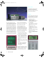
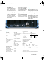
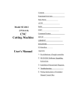
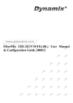
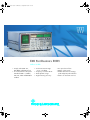
Eshs_de.fm Seite 1 Mittwoch, 8. September 1999 1:40 13
EMI Test Receivers ESHS
9 kHz to 30 MHz
• Comply with CISPR 16-1,
VDE 0876 and ANSI C63.2
• For measurements to European
• Level measurement range
−36 to +137 dBµV
• Frequency resolution 10 Hz
Standards 55011 to 55022,
• Wide dynamic range
ETS, FCC, VCCI and VDE 0871
• High measuring accuracy
to 0879
• Five preselection filters
• Battery or AC supply
• Parallel detectors for average,
peak and quasi-peak indication
• Macros for automatic test runs
Eshs_de.fm Seite 2 Mittwoch, 8. September 1999 1:40 13
Functions
Features
The EMI Test Receivers ESHS10 and 30
• Frequency range 9 kHz to 30 MHz
are double-conversion heterodyne re-
• RF attenuator switchable in 10-dB
ceivers covering the frequency range
steps in range 0 to 120 dB; high
from 9 kHz to 30 MHz. They can be ma-
pulse loading capacity of input
permanently activated peak detectors
nually operated, featuring high frequency resolution and accurate level in-
attenuator (100 mWs)
• Preamplifier with wide dynamic
• Logarithmic amplifier with more
than 70 dB dynamic range
• 12-bit A/D converter with short
conversion time
• IF filters with low delay distortion
• Flash EPROMs allowing convenient
and fast firmware updating
dication, both average and quasi-
range, can be switched between
peak.
preselection filter and 1st mixer
• Digital level indication on LC dis-
• Crystal-controlled synthesizer as
play and analog level indication
Thanks to the built-in intelligence of the
1st LO, variable in 10-Hz steps,
on moving-coil meter taking into
test receivers, the time required for
sweep mode for fast frequency
account transducer factors and
measurements is reduced considerab-
scans
their units
ly. Being specialists for EMI measurements to
CISPR,
CENELEC, ETSI,
FCC, VCCI and
VDE standards,
these test receivers furnish results at a speed and
accuracy not
possible previously.
Their real
strength, however, is the automatic measurement of RFI voltages. For this
measurement,
the test receivers
control the artificial mains network, detect the line with the highest RFI level,
compare the results with the permissible limits and furnish a comprehensive
test report with all the necessary information.
• High-level input mixer ensuring
high isolation of 1st LO
• Field-strength measurements using
test antennas
• Highly linear envelope detector
with more than 70 dB dynamic
range
Both receiver models combine three
classes of instruments in one:
– a compact, manually tunable and
battery-operated test receiver
– an automatic test receiver which
automatically performs measurements and reports the results
– a system-compatible test receiver
2
EMI Test Receivers ESHS
• Peak, average and quasi-peak detectors operating in parallel
• Peak indication with automatic
consideration of IF bandwidth
correction factors for measuring
broadband interference (PK/MHz)
• Automatic overload detection in
mixer stages and in test channel by
• High measuring accuracy: error
≤1 dB; typ. ≤0.5 dB
• Detection of faulty modules by
built-in selftest facilities
Eshs_de.fm Seite 3 Mittwoch, 8. September 1999 1:40 13
Result of complete, automatic RFI voltage measurement to CISPR 22,
class B.
Curves: fast prescan
measurement using
peak (blue) and average
detector (green) simultaneously.
*/+: result of final measurement with long
measuring time (1 s) at
frequencies with highest
levels of prescan measurement;
*: quasi-peak value,
+: average value. List of
final measurement results is plotted separately.
Time required for complete measurement including documentation:
approx. 4 min
• Manual operation or automatic test
with spectrum display on screen
• Built-in 3½" disk drive for storing
test results and instrument settings
• Built-in tracking generator for attenuation and gain measurements
Manual operation
For solving complex EMC problems,
manual measurement often is the most
efficient way, since the operator can
make full use of his experience in identifying interference sources. ESHS10
and 30 feature conventional test receiver operation with tuning knob, indication of results on a meter and built-in
loudspeaker. ESHS30 provides IF analysis in addition.
The clear arrangement of the controls –
all keys being assigned one function
• Automatic calibration at a keystro-
• Output of results as lists and dia-
only – and the LC display of the selected
ke with the aid of a high-precision
grams on printer or plotter inclu-
parameters such as attenuation, band-
built-in 100-kHz harmonics genera-
ding limit lines and user-definable
width and detector ensure great ease of
tor
labelling
operation. The display is easy to read
• Demodulator circuits for AM and
A0; headphones connector and
built-in loudspeaker
• Automatic monitoring of all synthesizer loops and supply voltages du-
• Nonvolatile storage of 9 complete
transducer factors and limit lines
• Manual operation or automatic test
The input keys for automatic measure-
ring operation
ments are arranged on the left of the
Additional features of ESHS30
preamplifier)
• Measurement of voltage, field
front panel. A row of menu keys are
provided below the screen to enter fre-
without preamplifier, third-order intercept point typ. 20 dBm (without
Automatic operation
with report on printer or plotter
• Wide dynamic range: noise figure
typ. 5 dB with preamplifier, 10 dB
in any ambient light.
instrument settings and 22 different
• IF analysis for visual check of inter-
quency scans, limits, transducer fac-
ference spectrum in manual measu-
tors, configuration data and macros for
rement mode; IF analysis module
test routines.
strength, current and pulse spectral
with resolution bandwidth of 1, 3
density with full indication of units
and 10 kHz; IF analysis executed
In a frequency scan (lin or log), up to
automatically during level measu-
five subscans are covered; each subs-
rement
can can be assigned a specific test re-
• Automatic consideration of frequency-dependent transducer factors
• Indication of level on analog meter
and digital display with 0.1-dB resolution
• 60-dB operating range also for
quasi-peak and average indication
• Optimal result display for every
application
• Display of interference spectra
ceiver setting. Nonvolatile storage of
22 limit lines and transducer factors
with up to 50 values is possible. By
(RF ANALYSIS) including limit lines
combining the transducer factors, all
on low-emission screen
configurations occurring in practice
• Full storage and listing of results
can be covered.
EMI Test Receivers ESHS
3
Eshs_de.fm Seite 4 Mittwoch, 8. September 1999 1:40 13
Remote control
The IEC/IEEE-bus interface complies
with the latest standard IEEE 488
Part 2. The measured values are output
with a resolution of 0.01 dB.
Interfaces
For further signal evaluation and for driving or feeding add-on units, ESHS10
and 30 have the following interfaces:
• IEC/IEEE-bus interface
• Coding and supply socket
(ANTENNA CODE) for active antennas and other accessories
The results of a frequency scan are
mation is automatically added to the
usually first displayed in graphical form
parameters known to the ESHS such as
(80 kHz OUTPUT) for evaluating
on the screen and then output on a prin-
date, time and receiver settings.
the IF signal eg with an oscillos-
ter as a list and/or on a plotter as a
• IF output 80 kHz
cope
graph. Time can be saved by simulta-
Macros for automatic test runs
neous printing of the lists and plotting of
(ANALYSIS OPTIONS) match the
(VIDEO OUTPUT) for evaluating
the graphs. Plotting is also possible du-
ESHS10 and 30 to the specific configu-
the detected IF signal eg with an
ring the frequency scan so that the desi-
ration, device under test and measure-
red document is already obtained du-
ment specification. Being thus prepa-
ring the measurement. Any relevant in-
red, the test receivers perform the follo-
formation can be added to the test re-
wing sequences automatically:
port, either by entering it via a line editor or, more conveniently, via an MF2
keyboard that can be connected. Infor-
the peak and/or average detector
quencies – for RFI voltage measurements on all phases of the artifical mains network (LISN) – using
the average and/or quasi peak
detector
• Report of results on printer or plotter
• ESHS30: storage of results on floppy disk
• Determination of critical frequencies by means of limit lines with
data reduction to shorten the
measuring time
The minimum configuration consisting
of ESHS10 or 30, artificial mains network (LISN) and plotter is already a
powerful and cost-effective test set.
EMI Test Receivers ESHS
oscilloscope
• Connector for an MF2-compatible
keyboard for text entry
• Input for an external reference frequency (5 or 10 MHz, automatic
• Fast prescan measurement using
• Final measurement at critical fre-
4
• Envelope detector output
detection)
Eshs_de.fm Seite 5 Mittwoch, 8. September 1999 1:40 13
• USER INTERFACE with
– RS-232 interface for reprogram-
– 6 TTL ports for driving external
devices, eg for phase selection
of the Artificial Mains Networks
ESH2-Z5 and ESH3-Z5
when updating the firmware via
The service-friendly modular design of
an AT-compatible computer
the ESHS10 and 30 in conjunction with
a consequent design to EMC rules inclu-
• Parallel interface
– input for external triggering of
measurements
– outputs for the analog display
voltage with and without simulation of the meter response for
connecting a discontinuous inter-
Design
ming the built-in flash EPROMs
(PRINTER INTERFACE) for connec-
ding the low-emission screen ensures
ting a printer
excellent results regarding RFI emission
• IF output 74.7 MHz for connecting
and immunity.
a panoramic display (ESHS10 only)
• Connector (11 to 33 V) for battery-
A faulty module can easily be found by
powered operation, eg in a vehicle
the built-in selftest and replaced with a
minimum of effort and without affecting
ference analyzer
the other modules.
Specifications
Frequency range
Frequency setting
Display
Resolution
Setting error
RF input
VSWR
Oscillator reradiation at RF input
(0 dB RF attenuation)
without preamplifier
with preamplifier
Preamplifier
Gain
Preselector
Maximum input level
(with and without preamplifier)
RF attenuation 0 dB
DC voltage
Sinewave AC voltage
Pulse spectral density
RF attenuation ≥10 dB (DC-coupled)
DC voltage
Sinewave AC voltage
Max. pulse voltage (10 µs)
Max. pulse energy (10 µs)
9 kHz to 30 MHz
1. with tuning knob in 10-Hz, 10-kHz
steps or any step size (switch-selected)
2. numerical keyboard entry
3. in steps of any selectable size
4. automatic scanning (RF analysis)
7-digit LCD
10 Hz
<3 × 10 −6 +30 Hz
Zin =50 Ω, N connector, female
<1.2 with ≥10 dB RF attenuation,
<2 with 0 dB RF attenuation
<20 dBµV
<10 dBµV
switchable between input filter and
1st mixer
10 dB
five bandpass filters
9 kHz to <150 kHz
150 kHz to <4.05 MHz
4.05 MHz to <12.8 MHz
12.8 MHz to <21.55 MHz
21.55 MHz to 30 MHz
Interference rejection, non-linearities
Image-frequency rejection
1st IF
>90, typ. 100 dB
2nd IF
>75 dB
IF rejection
>90, typ. 100 dB
Intercept point d3, with |f1-f2 | ≥100 kHz and 0 dB RF attenuation
Preamplifier
off
on
Level (f1, f2) at receiver input
fin <2 MHz
fin ≥2 MHz
Intercept point k2
IF bandwidths
Nominal
bandwidth
−3 dB
(±20%)
−6 dB
200 Hz 1)
150 Hz
200 Hz
+20/−30 Hz
9.5 kHz
±0.5 kHz
10 kHz )
7V(^
= 1 W)
137 dBµV
700 V
100 mWs
−20 dBm
typ. 0 dBm
>0 dBm
typ. +5 dBm
>20 dBm
RF shielding
Voltage indication at a field strength of
10 V/m with 0 dB RF attenuation (f ≠fin) <−10 dBµV
Additional error in quasi-peak
indication range
<1 dB
Intermediate frequencies
1st IF
74.7 MHz
2nd IF
80 kHz
2
7V
130 dBµV
96 dBµV/MHz
−10 dBm
typ. 15 dBm
>15 dBm
typ. +20 dBm
>40 dBm
7 kHz
Shape factor
BW6 dB/BW50 dB =1:8 (typ.)
BW6dB/BW60 dB =1:3.5 (typ.)
1) Meets tolerances to CISPR 16.
2) Meets tolerances to CISPR 16 (min. 8 kHz, max. 10 kHz) and complies
with MIL tolerance (10 kHz ±10%).
EMI Test Receivers ESHS
5
Eshs_de.fm Seite 6 Mittwoch, 8. September 1999 1:40 13
Noise indication
Preamplifier
Average value, BW=200 Hz
fin =9 to 50 kHz
fin >50 kHz
off
on
<−24 to <−30 dBµV <−30 to <−36 dBµV
<−30 dBµV
<−36 dBµV
typ. −35 dBµV
typ. −41 dBµV
Average value, BW=10 kHz
fin > 50 kHz
<−14 dBµV
<−20 dBµV
typ. −17 dBµV
typ. −25 dBµV
Peak value,
(typ. increase as against
+11 dB
average value)
Quasi-peak
Band A (9 to 50 kHz)
typ. −24 to −30 dBµV typ. −30 to −36 dBµV
(50 to 150 kHz) typ. −32 dBµV
typ. −38 dBµV
Band B (≥150 kHz)
typ. −13 dBµV
typ. −19 dBµV
PK/MHz (BW=10 kHz)
typ. 34 dBµV/MHz typ. 28 dBµV/MHz
Voltage measurement range (f in >50 kHz)
Lower limit (additional error caused by inherent noise <1 dB
Preamplifier
off
on
Average indication (AV)
BW=200 Hz
<−26 dBµV, typ.−31 dBµV <−32 dBµV, typ. −37 dBµV
BW=10 kHz
<−10 dBµV, typ.−13 dBµV <−16 dBµV, typ. −20 dBµV
Peak indication (PK)
BW=200 Hz
typ. −8 dBµV
typ. −14 dBµV
BW=10 kHz
typ. +10 dBµV
typ. +4 dBµV
Quasi-peak indication (QP)
CISPR band A
(pulse freq. 25 Hz) typ. −30 dBµV
typ. −36 dBµV
CISPR band B
(pulse freq. 100 Hz) typ. −11 dBµV
typ. −17 dBµV
Upper limit
AV, PK, QP
137 dBµV (RF attenuation ≥10 dB)
Inherent spurious response
<−10 dBµV (equiv. input voltage)
Level display
digital in dBµV, dBµA, dBm,
dBµV/m, dBµA/m, dBpW
analog
Operating ranges
Screen (RF analysis) (ESHS30 only)
Resolution
Display range
X axis (frequency)
Y axis (level)
Display modes
Averaging, hold and measuring
times
Measuring error
AV for S/N >16 dB
Level calibration
Demodulation modes
IF analysis (ESHS30 only)
Display range
Resolution
Nominal bandwidth 10 kHz
3 kHz
1 kHz
Sweep time
Level display range
Input attenuation
Date, time of day
6
EMI Test Receivers ESHS
3½ digits, resolution 0.1 dB
on moving-coil meter in operating range of IF detector with additional digital
display of lower range limit
30, 60 dB
5" CRT with digital display memory
1024 x 1024 pixels
freely selectable between 9 kHz and
30 MHz
10 to 200 dB, adjustable
average (AV),
peak (PK),
spectral density measurement (PK/MHz),
quasi-peak (QP)
1 ms to 100 s (1/2/5 steps)
<1 dB (digital display),
typ. <2 dB (analog display)
harmonics generator
Floppy disk drive (ESHS30 only)
Formatting
Data format
Connectors and interfaces
Remote control
Remote-control connector
Plotter
to IEC 625-2 (IEEE 488.2)
24-contact Amphenol connector
via IEC/IEEE-bus interface
Front-panel outputs
Supply and coding connector
for antennas etc
AF output
EMF
12-contact Tuchel connector
Zout =10 Ω, jack JK34
adjustable up to 2 V
Generator output (ESHS30 only)
EMF
N connector, female, 50 Ω
96 dBµV±1 dB
Rear-panel outputs
IF 74.7 MHz (ESHS10 only)
Gain ref. to RF input
(RF attenuation 0 dB)
Bandwidth (−3 dB)
IF 80 kHz
EMF in range of analog level
display for unmod. sinewave
signal:
Operating range 30 dB
60 dB
Bandwidth=IF bandwidth
Video output (envelope detector)
EMF in range of analog
level display:
Operating range 30 dB
60 dB
User interface
Printer connection
Keyboard connection
Rear-panel inputs
Ext. reference frequency
Required level
Frequency
Ext. battery
Required voltage
Rated temperature range
Storage temperature range
ESHS30: temperature range for
floppy disk drive
Mechanical stress
EMC
10 kHz
1:4
3 kHz
1:6
1 kHz
1:9
50 ms to 10 s
(adjustable in 1/2/5 steps)
80 dB
0/20 dB, selectable
internal clock, permanently operated
from internal battery
Zout =50 Ω, BNC connector, female
10 dB without preamplifier,
20 dB with preamplifier
>2 MHz or bandwidth of preselector
Zout =50 Ω, BNC connector, female
1 to 30 mV
1mV to 1 V
BNC connector, female
4 to 126 mV
4 mV to 4 V
25-contact Cannon connector;
includes 6 control lines for an external
device (eg artificial mains network),
display voltage (analog) with and without simulation of meter response, input for external triggering, RS-232-C interface for firmware updating
parallel interface, 15-contact Cannon
connector
DIN connector (5-contact) for MF2 keyboard
BNC connector, female
EMF ≥1 V from 50 Ω
5/10 MHz
3-contact connector
11 to 33 V
General data
A0 (zero beat)
A3 (for A3E emissions)
10 kHz to 2 MHz in 1, 2, 5 steps
−3 dB Shape factor
(±20%) BW 3dB :BW 60dB
3½", 1.44 Mbyte formatted
MS-DOS-compatible
HP-GL or binary
Power supply
AC supply
Battery
Internal (ESHS10 only)
External
ESHS10
ESHS30
−10 to +55°C
(no condensation allowed)
−25 to +70°C
+5 to 50°C
shock-tested to MIL-STD-810D
(shock spectrum 40 g), vibration-tested
to MIL-T-28800D, class 5; complies with IEC Publ. 68-2-6
to EMC directive of EU (89/336/EEC)
and German EMC law
100/120/240 V ±10%,
230 V +6/−10%, 47 to 420 Hz (80
VA)
safety class I to VDE 0411 (IEC348)
12 V, 10 Ah,
operating time approx. 4 h
11 to 33 V, 1.2 A at 24 V,
2.3 A at 12 V
2.1 A at 24 V,
3.9 A at 12 V
Eshs_de.fm Seite 7 Mittwoch, 8. September 1999 1:40 13
Dimensions incl. controls (W × H × D)
ESHS10
435 mm × 236 mm × 363 mm
ESHS30
435 mm × 236 mm × 463 mm
Weight
ESHS10
ESHS30
21 kg/18 kg with/without batteries
28.6 kg
Ordering information
Order designation
EMI Test Receiver ESHS10
EMI Test Receiver ESHS30
Accessories supplied
ESHS30 in addition
1004.0401.10
1002.9001.30
power cable, connector for external
battery, operating manual,
N- to-BNC adapter
hood for screen
Recommended extras
For interference measurements:
RF Current Probe
(9 kHz to 30 MHz)
ESHS30:
Current Probe 20 Hz to 100 MHz
Active Probe
(9 kHz to 30 MHz, high-impedance)
Passive Probe
(9 kHz to 30 MHz, VDE 0876)
Four-line Artificial Mains Network
(9 kHz to 150 kHz/30 MHz,
VDE 0876)
Four-line Artificial Mains Network
(150 kHz to 30 MHz, 200 A)
Double Two-Wire ISN to CISPR22 for
unshielded telecommunication ports
Four-Wire ISN to CISPR22 for
unshielded telecommunication ports
Antenna Impedance Converter
Two-line V-Network
V-Network 5 µH || 50 Ω
Attenuator (20 dB, 10 W)
Rod Antenna
Rod Antenna (MIL)
Loop Antenna (9 kHz to 30 MHz)
Loop Antennna (9 kHz to 1 MHz)
Inductive Probe
Tripod
Wooden Tripod (for HFH2-Z6)
Pulse Limiter 9 kHz to 30 MHz
Highpass filter 150 kHz
Option
3 additional RJ45 adapter sets
for ENY41
ESH2-Z1
0338.3516.52
EZ-17
0816.2063.02
ESH2-Z2
0299.7210.52
ESH2-Z3
0299.7810.52
ESH2-Z5
0338.5219.52
ENV 4200
1107.2387.02
ENY22
1109.9508.02
ENY41
EZ-12
ESH3-Z5
ESH3-Z6
ESH2-Z11
HFH2-Z1
HFH2-Z6
HFH2-Z2
HFH2-Z3
HFH2-Z4
HFU-Z
HZ-1
ESH3-Z2
EZ-25
1110.0175.02
1026.4800.02
0831.5518.52
0836.5016.52
0349.7518.52
0335.3215.52
0837.1866.54
0335.4711.52
0335.6214.52
0338.3016.52
0100.1114.02
0837.2310.02
0357.8810.52
1026.7796.02
ENY4-B1
1109.9950.02
Other accessories
6-V Lead Acid Storage Battery,
maintenance-free, 10 Ah (2 required)
(for ESHS10)
Keyboard (English)
Keyboard (German)
Headphones
Service Manual ESHS10
Service Manual ESHS30
Service Kit
19" Rack Adapter
with front handles
without front handles
Set of Front Handles
Cables
RF Connecting Cable (BNC)
(ESHS30)
IEC-bus Connecting Cable
1m
2m
Printer Cable
Control Cables for artificial mains
networks
from ESHS to ESH3-Z5,
2m
from ESHS to ESH2-Z5,
2m
from ESHS to ENV4200, 3 m
Control Cables for artificial mains
networks in shielded cabins
(both cables required)
from ESHS to ESH3-Z5,
2m
10 m
from ESHS to ESH2-Z5,
2m
10 m
from ESHS to ENV4200, 3m
10 m
Feeder Cables for active antennas
in shielded cabins (two required)
3m
10 m
EZ-8
0338.4012.00
1009.5001.32
1009.5001.31
0110.2959.00
1004.0553.24
1003.0272.24
0816.1067.02
ZZA-95
ZZA-951
ZZG-95
0396.4911.00
0396.9488.00
0396.5176.00
PCK
PCK
EZ-11
0292.2013.10
0292.2013.20
0816.1767.02
EZ-14
EZ-13
EZ-21
1026.5341.02
1026.5293.02
1107.2087.03
EZ-14
EZ-6
EZ-14
EZ-5
EZ-21
EZ-21
1026.5341.02
0816.0683.02
1026.5341.02
0816.0625.02
1107.2087.03
1107.2087.10
HZ-3
HZ-4
0837.3469.02
0816.0519.02
PSA-Z1
PSA-Z1
Certified Quality System
ISO 9001
DQS REG. NO 1954-02
EMI Test Receivers ESHS
7
Eshs_de.fm Seite 8 Mittwoch, 8. September 1999 1:40 13
Please send me an offer
❏
I would like a demo
❏
Please call me
❏
I would like to receive your free-of-charge CD-ROM catalog
Others:
–––––––––––––––––––––––––––––––––––––––––––––––––––
Printed in Germany
❏
999 (U we)
Fax Reply (EMI Test Receivers ESHS)
–––––––––––––––––––––––––––––––––––––––––––––––––––
Name:
––––––––––––––––––––––––––––––––––––––
Company/Department:
––––––––––––––––––––––––––––––––––––––
Position:
––––––––––––––––––––––––––––––––––––––
Address:
––––––––––––––––––––––––––––––––––––––
––––––––––––––––––––––––––––––––––––––
––––––––––––––––––––––––––––––––––––––
Country:
––––––––––––––––––––––––––––––––––––––
Telephone:
––––––––––––––––––––––––––––––––––––––
Fax:
––––––––––––––––––––––––––––––––––––––
E-mail:
––––––––––––––––––––––––––––––––––––––
ROHDE&SCHWARZ GmbH & Co. KG ⋅ Mühldorfstraße 15 ⋅ D-81671 München ⋅ P.O.B. 8014 69 ⋅ D-81614 München ⋅ Telephone +49894129-0
Internet: http://www.rsd.de ⋅ CustomerSupport: Tel. +491805124242, Fax +4989 4129-3777, E-mail: [email protected]
PD 756.3260.23 ⋅ Trade names are trademarks of the owners ⋅ Subject to change ⋅ Data without tolerances: typical values
–––––––––––––––––––––––––––––––––––––––––––––––––––