1
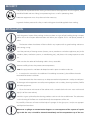
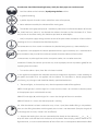
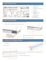
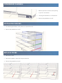
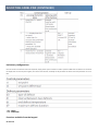
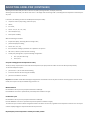
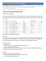
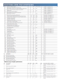
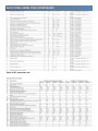
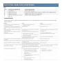
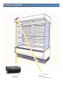
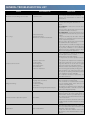
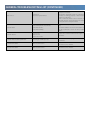
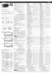
Installation, Operation and Troubleshooting Instructions Reach-In Refrigerators For Models: RC Print Date: June 19, 2012 West Meadow Rise, Castle Donington, Derby, DE74 2HL. Phone: +44 (0) 1332 850090 Fax: +44 (0) 1332 810685 Website: www.interlevin.co.uk E-Mail: [email protected] T H A N K Y O U Thank you for purchasing a Interlevin Refrigerator! This unit has passed our strict Quality Control Inspection and meets the high standards set by Interlevin. You have made a quality investment that with proper maintenance will give you years of service. Please read the following installation and maintenance instructions before installing or using your unit. If you have any questions, please call our Customer Service Department at +44 0 1332 850064. IMPORTANT INFORMATION - PLEASE READ Please read these instructions carefully before installing or using. If recommended procedure are not followed, warranty claims will be denied. Interlevin reserves the right to change specifications and product design without notice. Such revisions do not entitle the buyer to corresponding changes, improvements, additions or replacements for previously purchased equipment. A detailed Owners Manual with a troubleshooting guide, parts lists and additional information can be ordered from the factory. I N S TA L L AT I O N I N S T R U C T I O N S Proper installation is the first step to operation. We recommend that your refrigerator be installed by authorized Interlevin Certified Installer. Receiving Shipment All units are performance tested and thoroughly inspected prior to shipment. Upon leaving the factory, all units are in perfect condition. Upon receipt, examine the exterior of the shipment packaging for any signs of rough handling. If the cabinet is damaged, it should be note on the delivery slip or bill of lading and signed. A claim must be filled immediately against the carrier indicating the extent and estimated cost of damage incurred. Uncrating Tools Needed: 3/4’’ Box Wrench Adjustable Wrench Level WARNING: Never lay your refrigerator down on either its back, front or sides. This allows compressor oil into the refrigerant lines which can damage the compressor at start-up. If the unit is laid down, it must be set upright for a minimum of 12 hours before starting the compressor. Failure to adhere to the above recommendation will void the warranty. 1. Split plastic wrap along one of the cardboard posts. Remove and discard all packaging material, tape and interior components. 2. Move cabinet as close to final location as possible before removing skid. 3. Remove the shipping skid by tipping the cabinet forward. Remove the shipping bolts with 3/4’’ box wrench while the cabinet is held in one direction. Repeat this procedure while the cabinet is held in the opposite direction. 4. Use extreme caution when removing the wooden skid, especially when the last bolt is removed. If not properly blocked, the skid will fall to the floor. Locating Your New Storage Refrigerator Consider the following when selecting a location for your refrigerator. 1. Clearance - There must be a minimum clearance of 10’’ between the top of the refrigerator and the celling. 2. Floor Load - The floor on which the cabinet will rest must be free of vibration and suitably strong enough to support the combined weights of the cabinet plus the maximum product load. 3. Ventilation - The air cooled, self-contained refrigerator requires a sufficient amount of cool, clean air. Avoid placing the refrigerator near heat generating equipment such as ovens, ranges, heaters, fryers, steam kettles, etc. and out of direct sunlight. Avoid locating the self-contained refrigerator in an unheated room, or where the room temperature may be below 12ºC. Leveling Cabinets must be leveled when installed. Failure to level your cabinet may result in doors not sealing, closing properly or condensate water not draining properly. Legs - Rotate the foot of the leg with an adjustable wrench to achieve desired height for leveling. Cabinet Cleaning Prior to placing your new refrigerator and all shelves, pans and slides into operation, it is advisable that the interior be washed thoroughly with a mild detergent and water solution. Rinse with clear water and a sanitizing solution. Allow cabinet to air dry Installing Shelves All cabinets with shelves are supplied with pilasters and shelf clip supports. Shelves are easily installed by inserting the shelf support clips into the pilasters so they fit tightly. Align the shelf so the smaller fill wires run from front to rear and rest the shelf on the clips. Electric Supply Wiring should be done by a qualified electrician in accordance with local electrical codes. A separate earth wire must be supplied for all installations. A properly wired refrigerator will assure proper operation. Electrical supply requirements are on the cabinet serial/data plate. It is recommended that a direct, properly protected line of the proper size wire be installed from the main supply to your refrigerator. To assure that the correct voltage is being supplied, while the refrigerator is in operation take a voltage reading at the motor-compressor electrical connections, or as close to the motor-compressor as possible. All refrigerator electrical systems are internally earthed. Temperature Control Temperature control should be set to maintain a temperature of 38ºF (3.3ºC) to 40ºF (4.4ºC) for refrigerators. Installation Checklist After the cabinet has been installed, leveled and cleaned as described, refer to the following checklist prior to start-up. Check for proper electrical connection. Check exposed refrigeration line connections for leaks. Make sure refrigeration lines are not dented, kinked or rub- bing. Check condenser fan for freedom to rotate without striking any stationary parts. Check that cabinet is level. Product Load After the refrigerator has been started and reaches the proper storage temperatures, food may be loaded. For optimum energy efficiency, we recommend allowing a 1-1/2’’ clearance between the interior cabinet wall and product load. ENVIROMENTAL PROCTECTION This equipment does not contain CFC’s. Neither inflammable gases. Unpacking All packing materials are recyclable and should be eliminated according to local regulations. Plastic bags must be kept away from children in order to avoid potential hazard. End of life cycle When the product reaches the end of its life cycle, we recommend to: 1. Make it unusable (ex. by cutting the power supply cable); 2. Remove the doors and other element, which eventually could be harmful to children. 3. In the case of complete dismantling, we recommend to strictly respect the local regulations regarding waste disposal. SECURITY The personnel responsible for the moving and instillation of the equipment must have gloves, which should be flexible and anti-sliding, have protective glasses as well as protecting shoes. Protection equipment must always be used when necessary. In general the best practices for safety in work and hygiene should be applied when working. INSTALLATION Verify the general aspect of the package. In the case there are signs of bad handling during transport, referrer this in the transport documentation and inform your supplier. If all is well please proceed as follow: 1. The location where the cabinet will be installed is very important for its good working and consequent energy saving. Avoid the proximity of heating sources (heaters, stoves, condensers and other appliances, etc.) drafts (windows, doors, ventilation systems, air conditioning, etc.), and places with strong exposure to solar rays. Make sure that the socket of the feeding cable is always accessible. Remove carefully plastics that protect some components. Note: this equipment has not been developed to work in open air neither under rain. 2. In case that this manual has also additional “Assembling instructions”, please follow the order mentioned for correct installation. 3. We recommend that when necessary an adequate mechanical protection is made, to avoid possible damages to the equipment caused by moving objects such as trolleys, cleaning machines, forklifts and other equipment. 4. Clean the interior and exterior of the cabinet with a smooth cloth and warm water with neutral soap (5% of the water volume). Avoid that is gets splashed by the cleaning products used to wash the establishment. The substances used in cleaning of the floors can attack chemically the components of the unit. Dry carefully all the rests of water with the help of a sponge. On the glass parts / acrylics use appropriated liquid to clean them. When ever a spillages or contamination happens as a consequence of the rupture of a package inside the unit, it should be cleaned immediately and the evaporation tray of the con- densed water should be drained right away. Verify the drain pipes are not obstructed. 5. Level the cabinet on the horizontal, by adjusting the feet to allow: Its good functioning, A perfect disposal of residual waters and defrost waters of evaporator, Noise reduction caused by the vibration of the moving parts. 6. The condensation group (compressor + condenser), commonly installed on the bottom of the cabinet, should not have, around it, any obstacle that reduces the necessary free circulation of air. Therefore, near the air circulation zones, you should not put boxes or other objects. 7. Verify it the power supply voltage and the tension of the place where the cabinet will be installed is according to what is indicated on the identification plate. The connection must have a earth wire element that, besides being necessary, is demanded by law. The appliance is not equipped with electric protection devices against overload, so it is recommend to verify the electric safety level of the installation network where the cabinet will be installed. Do not connect any other appliance to the same power socket, nor use socket extensions. We decline all liability for eventual injuries that may result to people, animals or products (good) for not respecting these instructions. 8. Turn on the cabinet 1 (one ) hour after it has been installed. On the appliances equipped with electronic thermostat temperature regulation is made according to the specific instructions that are supplied with the cabinet. This thermostat is already programmed from factory,; any changes made should be done by specialized technicians. 9. The control lights, in the case they exist, show the operation mode of the appliance: GREEN Switch light (0 / !) with the light ON > means that the switch is on and there is electrical power in the equipment (units with electrical tension). ORANGE Switch light () with the light ON > means that the light of the unit it turned on. ORANGE Control On > means that the compressor is working. 10. After the cabinet has been switched on wait, at least 2 (two) hours before filling it with products. Make sure that filling the cabinet with the goods, the air circuit is not obstructed. (Example: the grids of air discharge and air intake, “Suction” and “Insufflation”) 11. Respect the loading limits that are mentioned either directly on the cabinet by “_________” or by the sticker aside the label with the features of the cabinet. Never display, products above this refrigeration level, as it can create disturbances of the air flow and as a consequence deteriorate the food products displayed. The shelves (in case they exist) placed above the refrigeration level they are exclusively to display products that are not in need of refrigeration (excluding the models that are conceived for such). We remind that this equipment has not been conceived to lower the temperature of the food products displayed, but to maintain the temperature of the food products there placed. Food products with temperature above the one recommend for the working of the equipment must not be placed inside the unit. Do not leave the food products in boxes or pallets more than the necessary time to load the equipment (unit). In the food display equipment; food products must be removed during the night and placed in a Cold Room or similar equipment to preserve the food temperature during the night. In order to optimize the working of the equipment and the conservation of the food products use only complements and accessories supplied with the unit. When the equipment is supplied with manual night curtains (that normally is an option), they must be opened and closed carefully in order to avoid the losing the vertical alignment and start to deteriorate. Night curtains should always be used in order to reduce energy consumption. When closing the night curtain do not forget to turn of the light inside the equipment. PERIODICAL MAINTENANCE 1. The appliance, when equipped with automatic defrosting programmer, should be switched off and cleaned (see “Cleaning” chapter) at least once a month. The accumulation of ice in the evaporator reduces the performance and makes the energy costs rise. Never remove the ice from the evaporator with metal objects such as knifes or cutting objects. When the evaporator has ice the ideal is to let it defrost naturally of the evaporator. Water resulting from daily defrosting is collected in a plastic recipient that must be emptied, whenever necessary. In some models this procedure is not necessary since the water is re-evaporated in an appropriate place. Special attention must be taken when a defrosting is made after ice is created in the evaporator, as the recipient for the condensed water may not have sufficient capacity and overflow. 2. Before any maintenance or cleaning operation the appliance must be unplugged in order to guarantee, that it is not connected to electric power. The plug must be removed from the socket in order to insure that there is no electrical current of any type. Then remove all the products that are inside the cabinet and place them in a cold room or an adequate conservation place. Whenever necessary to remove any protection or isolation all the procedures for this must be correctly followed. Never restart functioning without making sure that all the removed elements have been dully fitted on the appliance. Cleaning Internal and external cleaning must be done monthly with a soft cloth and warm water with neutral soap (5% of the water volume) without chlorine. In this chapter it is very important that the drainage hole of the condensed water is perfectly clear. Dry carefully all the rests of water with the help of a sponge. On the glass parts use appropriated liquid to clean them. Condenser cleaning should be made monthly or, whenever it shows impurities or dirt that may hinder or block free circulation of air. The removal of impurities or dirt must be done using a brush of soft hair (never use a metal brush), a vacuum cleaner or with air pressure flow. Replacement of the neon lamps 1. Disconnect the power socket. 2. Press both polycarbonate protection caps of the lamp. Rotate both - lamp / protection capsapproximately 90º and remove the lamp. In the case that the protection in polycarbonate is inserted, remove it with the help of a tool. 3. Rotate the lamp approximately 90º and remove it. 4. The lamp must be replaced by one with the same reference or equivalent. 5. To place a new lamp, repeat the same procedure in the opposite sense. As to the recycling of the used lamps respect the local legislations and regulations that apply. Important remarks Do not spill water over boxes or electric components. Do not use water pressure (jets) or any type of metallic objects in order to remove impurities or dirt. Do not use substances or materials that are abrasives or solvents, avoiding the use of muriatic acid as well as detergents with chlorine base or pure alcohol. CHARACTERISTIC TAG 1 3 2 9 7 6 5 4 10 11 8 1. 2. 3. 4. 5. 6. 7. 8. 9. 10. 11. Serial Number Model & Size Tension / Frequency ( V/Hz) Power (W) Current (A) Refrigerant Refrigerant Quantity IP Protection Resistances (W) Lighting (W) Climatic Range PANELS BOTTOM SIDE 1. Remove panel on the front side by lifting it up with a screwdriver. 2. Slide the side panels backwards and remove these panels. 3. Loosen the screws from the back panel and lift this panel out. 4. Reverse the procedure to install. ILLUMINATION/TUMBLE SWITCH 1. Remove the socket screws on the top side and turn light fixture towards yourself. 2. Replace lamp. 3. Remove wiring from switch and remove the switch by pushing the clamps on both sides. 4. Reverse the procedure to install. CONDENSER CLEANING 1. Remove panel on the front side by lifting it up with a screwdriver. 2. Cleaning the condenser as in the picture 3. Reverse the procedure to install. INSTALLING SHELVES 1. For removing the shelves is only necessary to push forward. 2. Reverse the procedure to install. REPLACE PROBE 1. Remove the Shelf 2. Remove the probe is shown for the picture beside 3. Reverse the procedure to install. ADJUSTING CAREL PJEZ INTRODUCTION Easy and easy compact are electronic microprocessor controllers with LED display, developed for the management of refrigera ng units, display cabinets and showcases. They exploit the experience and the success of the previous PJ32 range, with the objec ve of offering a product that is simpler and more economical. The structure of the parameters has been enhanced with new func ons for more dynamic and effec ve management of the temperature control and defrost. easy compact the smallest, most economical easy model, with one relay only, and a simplified display. Main characteris cs The following table lists the main features of the easy and easy compact controllers. USER INTERFACE AND START UP ADJUSTING CAREL PJEZ (CONTINUED) Display Keypads ADJUSTING CAREL PJEZ (CONTINUED) Preliminary configura ons Once the electrical connec ons have been completed, simply power-up the controller to make it opera ve. CAREL then recommends to check that the display does not show any alarm signals, then set the me and date, and finally set the parameters as desired. The main parameters are as follows: * SC1 - PROBE ** PS - PASSWORD Func ons available from the keypad On and off ADJUSTING CAREL PJEZ (CONTINUED) Switching the instrument ON: press UP for more than 3 s (when pressing the bu on, the display shows ON). Switching the instrument OFF: press UP for more than 3 s. The display shows the message “OFF”, alterna ng with the temperature measured by the set probe. In off status, the following func ons are disabled (if featured by the model): compressor control / duty se ng / con nuous cycle; defrost; fan control; alarms : ‘LO’, ‘HI’, ‘IA’, ‘cht’, ‘CHT’; door switch (A4= 7/8 ); buzzer (when available) While the following are enabled: temperature display, alterna ng with the message “OFF”; parameter display and se ng; alarms: “E0”, “E1”, “E2”; the internal mer rela ng to parameter ‘dI’ is updated. If ‘dI’ expires in OFF status, a defrost is performed when restar ng; auxiliary relay management, only in the following configura ons: H1= = 1/2 (“E0” alarm only) H1= 3, A4= 6; Set point se ng (desired temperature value) The easy and easy compact devices control the desired temperature (set point) inside the cabinet or cold room directly and dynamically. To view and modify the set point: press SET for 1 s, the set value will start flashing; increase or decrease the value using UP or DOWN; press SET to confirm the new value. Important: the PJEZM* models fi ed with keypad simply monitor the devia on from the set point and where necessary signal na alarm. On these models, the set point can only be modified using parameter “St”. Manual defrost Not available on the easy and easy compact thermometer models (M). Press DOWN for more than 3 s (ac vated only if the temperature condi ons are right. Con nuous cycle Not available on the easy and easy compact thermometer models (M). Press UP+DOWN for more than 3 s (ac vated only if the temperature condi ons are right). The con nuous cycle is used to maintain refrigera on ac ve in the cabinet or cold room, regardless of the temperature inside the unit. This may be useful for rapidly bringing the temperature below the set point value. Rapid display of the temperature read by the other probes ADJUSTING CAREL PJEZ (CONTINUED) Press the DOWN bu on to scroll the temperatures read by the probes. Each me the DOWN bu on is pressed, the display will show the name of the probe Pr1, Pr2 or Pr3 (only on the models with 3 inputs and with mul func on input configured as a probe) and a er 1 s the temperature measured by the selected probe will be displayed. To display the other probes, press DOWN again. To return to the normal display, wait 3 s without pressing any bu ons (exit by meout). TABLES OF ALARMS AND PARAMETERS Table of alarms and signals When an alarm is ac vated, the display shows the corresponding message that flashes alterna ng with the temperature; if fi ed and enabled, the buzzer and the alarm relay are also ac vated. All the alarms have automa c reset (that is, they stop when the causes are no longer present), except for alarm ‘CHt’ which has manual reset (instrument on/off using the UP bu on or by disconnec ng the power supply). Pressing the SET bu on mutes the buzzer, while the code displayed and the alarm relay only go off when the causes of the alarm have been resolved. The alarm codes are shown in the table below: Descrip on of the main signals and alarms LED flashing The activation of the corresponding function is delayed by a timer, awaiting an external signal or disabled by another procedure that is already in progress. e.g. if is a continuous cycle in progress and a defrost is called, the latter will remain pending until the end of the continuous cycle, and the corresponding LED (defrost) will flash. E0 steady or flashing control probe error: probe not working: the probe signal is interrupted or short-circuited; probe not compatible with the instrument; The alarm signal E0 is steady if it is the only active alarm (the temperature value is not displayed), while it flashes if other alarms are active or the second probe is displayed. E1 flashing evaporator probe or food conservation probe error: probe not working, the probe signal is interrupted or short-circuited; probe not compatible with the instrument; ADJUSTING CAREL PJEZ (CONTINUED) E2 flashing condenser probe or food conservation probe error: probe not working, the probe signal is interrupted or short-circuited; probe not compatible with the instrument; IA flashing immediate or delayed alarm from multifunction digital input: check the multifunction input and parameters A4 and A7. dOr flashing open door alarm: check the multifunction input and parameters A4 and A7. LO flashing low temperature alarm. The probe has measured a temperature lower than the set point by a value that exceeds parameter AL: check parameters AL, Ad and A0. The alarm is automatically reset when the temperature returns within the set limits (see parameter AL). HI flashing high temperature alarm. The probe has measured a temperature higher than the set point by a value that exceeds parameter AH. check parameters AH, Ad and A0. The alarm is automatically reset when the temperature returns within the set limits (see parameter AH). EE displayed during operation or on power-up unit parameter reading error. See Data errors. EF displayed during operation or on power-up operating parameter reading error. See Data errors. Ed flashing The last defrost ended after exceeding the maximum duration rather than when reaching the end defrost set point. check parameters dt, dP and d4; check the efficiency of the defrost. The message disappears when the next defrost ends correctly. dF flashing defrost running: this is not an alarm signal, but rather a message that the instrument is running a defrost. Only shown if d6= 0. cht flashing dirty condenser pre-alarm: check parameters A4, Ac, AE and Acd. CHt flashing dirty condenser alarm: check parameters A4, Ac, AE and Acd. EtC flashing internal clock error. Data error ADJUSTING CAREL PJEZ (CONTINUED) In certain opera ng condi ons, the instrument may detect errors in the data saved. These errors may compromise the correct opera on of the instrument. If the microprocessor detects a data saving error, the display shows the message “EE”. If the fault persists, the controller needs to be replaced. If, on the other hand, the message disappears, it can con nue to be used. When “EE” error occurs frequently and/or remains for some me, the controller should be checked, as the original precision may not be guaranteed. Modifying the parameters Parameter naviga on The opera ng parameters, modifiable using the keypad, are divided into two types: frequent (type F) and configura on (type C). Access to the la er is protected by password (default= 22) to prevent accidental or unauthorized modifica ons. Accessing the type F parameters: press the SET bu on for more than 3 s (if there are ac ve alarms, mute the buzzer), the display shows the parameter code ‘PS’ (password); use the UP and DOWN bu ons to scroll the parameters. The LED corresponding to the category of parameters will be on (see Table 5.b); press SET to display the value associated with the parameter increase or decrease the value using the UP or DOWN bu on respec vely; press SET to temporarily save the new value and display the parameter again; repeat the procedure for any other parameters that need to be modified; press the SET bu on for more than 3 s to permanently save the parameters and exit the parameter se ng procedure. Accessing the type C parameters: press the SET bu on for more than 3 s (if there are ac ve alarms, mute the buzzer), the display shows the parameter code “PS” (password); press the SET bu on to access the password se ng; use the UP and DOWN bu ons to scroll the numbers un l displaying “22” (password to access the parameters); press the SET bu on to confirm the password; use the UP and DOWN bu ons to scroll the parameters. The LED corresponding to the category of parameters will be on (see Table 5.b); press SET to display the value associated with the parameter increase or decrease the value using the UP or DOWN bu on respec vely; press SET to temporarily save the new value and display the parameter again; repeat the procedure for any other parameters that need to be modified; press the SET bu on for more than 3 s to permanently save the parameters and exit the parameter se ng procedure. Se ng the default parameters To reset the default parameters: disconnect power from the instrument; reconnect power while holding the SET and DOWN bu ons; the display will show the message “CF”; a er a few seconds the instrument starts opera ng with the default configura on. Any different parameter se ngs will need to be updated. Table of easy parameters ADJUSTING CAREL PJEZ (CONTINUED) Table of easy compact parameters ADJUSTING CAREL PJEZ (CONTINUED) Table of EZY parameter sets ADJUSTING CAREL PJEZ (CONTINUED) Troubleshoo ng The following table shows a number of anomalous situa ons that may occur on the various models. The most frequent causes and corresponding checks are described: CONTROL LOCATIONS A B A: Light Switch: Thermostat B: Main 220V GENERAL TROUBLESHOOTING LIST Failure The device is not working, does not start. Not cooling Compressor broke down Refrigerant leaking Condensate water evaporation system Lights failed Possible Reason What to do No power to unit Check if plug is properly wired. Check if plug is earthed and neutral wired. Check if any circuit breaker is down in the electrical box. Condenser blocked. Evaporators blocked. Air flow in the condenser obstructed. It often happens that all the refrigeration components are working and still don’t cool. Check : The condenser – make sure it is clean otherwise clean it. Remove all the objects that may prevent the good air flow into the condenser. The evaporators - check evaporators for ice or blocked with products that may prevent the air flow. If they are blocked press dF button and wait until the ice is completely removed even if you need to repeat this operation. Remove all the objects that may prevent the good airflow into the evaporators. As general advice: avoid direct sunlight or heat sources that can affect on the device like heaters, projectors, ventilators or air conditioning equipment and/or ventilation that has direct effect on the refrigerated equipment. Compressor “burns” for: Too many starts. Lack of refrigerant. Power supply failure. Filter obstructed. Condenser obstructed. If the compressor is “burnt”, the technician who will replace it has to consider: Refrigerant recovery if still existing. Do not pour the oil of the replaced compressor. To be quick in the replacement so that the oil of the new compressor is not in contact a too long time with the air as this later is highly hygroscope (capacity of absorbing water). Once the circuit is sealed, make a good vacuum and recharge the quantity of refrigerant. Filters should be also replaced as these have the property of retaining undesirable particles in the installation and also humidity. The compressor should be replaced by one with identical features. Charging valve unscrewed. Poor use solder. Incomplete welding. Broken tubes. Attempted defrosting with pointed objects. Check if the device is working. If the condenser is not obstructed. If the condenser is not obstructed and if the fans are working switch of the devices as it looks like a leak refrigerant. Call engineer to detect the leak, to eliminate it and change the filters – make the vacuum and replace the refrigerant quantity. Heater burnt. According to the system you are using, if your equipment makes the power supply down or circuit breaker down, it is possible that one of the components has earthed wired and it may be the heater burnt. Note: these operations should be carried out by skilled people and when heaters are diving in water. Starter or tube failure If the tubes don’t light check them or starters. When you replace the tube and if this is still failing then replace the ballast. It may come from the oxidation of the terminals because of the humid ambient of these devices. GENERAL TROUBLESHOOTING LIST (CONTINUED) Water on floor Bad leveled. Evaporation system failed. If some water appears on the floor, see if the equipment is leveled. Check if the automatic system of evaporation of waters is working properly or drain waters system is not blocked. Some condensate waters can be released on the walls because of bad circulation of steam so keep the device away from walls. Controller failed Probe unwired from the terminals. Probe with cut wire. Probe with humidity. See if there is any message error on the display. Check that switches are well connected; if so call the technician to check for the possible failure. Controller “burnt” Power excess. Starts exceed. Water in the circuit. Replace the controller and check the origin of the failure. Controller with unsettled parameters Operating by unskilled people. Call the technician to reprogram the controller parameters. Condenser fans failed Failure by obstruction. Replace fans. Check the source of failure. Evaporator fans failed Water inside the circuit. Failure by obstruction. Replace the fans. Check the source of failure. Interlevin Refrigeration Ltd. West Meadow Rise, Castle Donington, Derby, DE74 2HL. Tel: +44 (0) 1332 850090 Fax: +44 (0) 1332 810685 Web: www.interlevin.co.uk Email: [email protected]