1
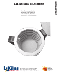
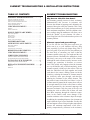
ELEMENT TROUBLESHOOTING & INSTALLATION INSTRUCTIONS TABLE OF CONTENTS ELEMENT TROUBLESHOOTING ELEMENT TROUBLESHOOTING . . . . . . .1 Why does an older kiln slow down? Why does an older kiln slow down? . . . . . . . . . . . . . . . . . . . . . . . . . .1 Elements expand and grow with age . . . . . . . . . . . . . . . . . . . . . . . . . .1 What if I see charred and blacked corners? . . . . . . . . . . . . . . . . . . . . .2 Factors shortening element life . . . . . . . . . . . . . . . . . . . . . . . . . . . . . .2 Element Terminal Burn-out . . . . . . . . . . . . . . . . . . . . . . . . . . . . . . . . .3 Old elements generally increase in their resistance. Mathematically this increase in resistance will decrease the amount of amperage and, ultimately, the amount of heat given off by the elements. This is why older kilns sometimes go so slowly and may not reach their maximum temperature. Periodic element resistance readings using the multimeter will allow you to check the “health” of your elements. Of course, a slow firing kiln is the first indication that you have an element problem. CHECKING ELEMENTS . . . . . . . . . . . . . . .3 Elements . . . . . . . . . . . . . . . . . . . . . . . . . . . . . . . . . . . . . . . . . . . . . . .3 Element Connections . . . . . . . . . . . . . . . . . . . . . . . . . . . . . . . . . . . . .4 HOW ELEMENTS ARE WIRED . . . . . . . . .4 Why is this important? . . . . . . . . . . . . . . . . . . . . . . . . . . . . . . . . . . . .4 Series Circuits . . . . . . . . . . . . . . . . . . . . . . . . . . . . . . . . . . . . . . . . . . .5 Parallel Circuits . . . . . . . . . . . . . . . . . . . . . . . . . . . . . . . . . . . . . . . . .5 Series-Parallel . . . . . . . . . . . . . . . . . . . . . . . . . . . . . . . . . . . . . . . . . . .5 Specific to non-sectional kilns: . . . . . . . . . . . . . . . . . . . . . . . . . . . . . .6 POWERED BOTTOMS . . . . . . . . . . . . . . . .6 OTHER TYPES OF ELEMENTS . . . . . . . . .6 Elements expand and grow with age Heavy-Duty elements . . . . . . . . . . . . . . . . . . . . . . . . . . . . . . . . . . . . .6 APM Elements . . . . . . . . . . . . . . . . . . . . . . . . . . . . . . . . . . . . . . . . . .6 Increasing Power in Your Kilns . . . . . . . . . . . . . . . . . . . . . . . . . . . . . .6 REMOVING OLD ELEMENTS . . . . . . . . . .7 CHECKING ELEMENTS . . . . . . . . . . . . . . .8 STRETCHING ELEMENTS . . . . . . . . . . . . .9 JUPITER ELEMENT STRETCH LENGTHS . . . . . . . . . . . . . . . . . . .9 IF ELEMENTS NEED TO BE STRETCHED . . . . . . . . . . . . . . . . . . .9 INSTALLING NEW ELEMENTS . . . . . . . .9 FIRST FIRING WITH NEW ELEMENTS . . . . . . . . . . . . . . . . . . . . .10 REPLACING ELEMENT HOLDERS . . . . .10 Method #1 Method #2 . . . . . . . . . . . . . . . . . . . . . . . . . . . . . . . . . . . . . . . . . . . . .10 . . . . . . . . . . . . . . . . . . . . . . . . . . . . . . . . . . . . . . . . . . . . .11 If you fire low-fire clay and glazes and never get above cone 4 or so, your elements will last a long time, especially if you are only bisque firing. This is good, to a point. If you only low-fire, the problem you are most likely to encounter over time is that the elements expand as they age. The length and the coil diameter increase. Meanwhile the atmosphere in the kiln slowly eats away at the metal of the element. Although the total resistance usually increases as the elements age, sometimes it decreases, or reverses itself. This usually only happens when the elements are very old but have not yet failed completely. As the element expands, it binds up in the corners. This can make the individual coils push together and touch each other in the corners, making a short cut for the electricity, reducing the amount of element material the electricity must pass through, and therefore reducing the resistance in the whole element. This may make it hotter in the kiln, but if there is a lot of element material jammed in the corners there will not be enough material left in the coiled form to radiate the heat generated by the increased amperage and decreased resistance. Only the parts of the wire not touching the coils on either side of them will emit heat. More amperage through the electrical components in the control could cause damage if the situation continues or the resistance drops far enough. In addition, the expanding diameter of an element can make it difficult to get it out of the holder. Usually this will not happen to those firing to higher temperatures because the maximum temperature of the kiln is quickly compromised by increases in the resistance, troubleshoot-elements 2004 L&L Kiln Mfg, Inc. P.O.B 1898, Boothwyn, PA 19061 3/1/2004 Rev 1.0 P:610.485.1789 Page 1 F:610.485.4665 E:[email protected] www.hotkilns.com ELEMENT TROUBLESHOOTING & INSTALLATION INSTRUCTIONS requiring the elements to be changed long before they can jam up in the corners. Also, high temperatures and glaze firings are more prone to eating through the element, causing it to fail, before the element can expand enough to cause the problems mentioned above. Use the multi-meter. Visually inspect your elements. What if I see charred and blacked corners? The coils that sometimes get squashed together in the corners do not always touch each other, but they may be close enough to allow the electricity to 'arc' across the gap. An electrical arc can generate extreme temperatures for the millisecond it arcs. Charred and blackened corners of the kiln are warning signs for this problem. Do not confuse this with what can be observed even with new elements; which is randomly sized sections of the coils glowing more quickly than other sections of the same coil. The annealing process of the wire causes this, and does not adversely affect the elements’ operation in the kiln. Factors shortening element life 1) Contamination (such as glaze or kiln wash). Silica, a main ingredient of both of these, attacks the element wire. 2) Tightly wound areas on element coils resulting from improper stretch. Have the elements been stretched evenly? This is important. If the element coils are bunched up along the length of the element the element will overheat where the coils are too close. Some replacement elements are shipped unstretched. Even prestretched elements may need some stretching. See section below on stretching elements. 3) Glaze accidentally rubbing off into holder and on element in loading kiln. If this occurs immediately vacuum the kiln and element holders thoroughly. Glaze will cause very rapid element failure. 4) Blow ups or explosion of bisque ware cause small pieces of clay to be blown into holder and element. If not immediately removed clay may melt, contaminating the element and element holder. Keep in mind that temperatures are considerably higher right next to the element so that you may very well exceed the clay troubleshoot-elements 2004 L&L Kiln Mfg, Inc. P.O.B 1898, Boothwyn, PA 19061 melting temperature next to the element even if the kiln temperature is correct for the clay body. To avoid explosions make certain clay is very dry before firing and, in the case of heavy handmade pieces, fire on low for a long period until you are sure ware is dried out thoroughly. If you hear a "pop" when firing such pieces, stop firing, cool the kiln. If blowup has occurred, vacuum all element grooves very thoroughly. If you have the DynaTrol use the PreHeat feature for this final forced drying. 5) Firing pieces too close to elements. We recommend at least 1-1/2" from piece to element. Further if large flat surfaces are parallel to kiln wall. 6) Reducing atmospheres will destroy elements. Do not use wood chips, oils and other materials to generate a reducing atmosphere. A very rapid element failure may result. NOTE: Reducing atmospheres are the opposite of oxidizing atmospheres (plain air is an oxidizing atmosphere). The word reducing comes from the ability of a reducing atmosphere to "reduce" oxides. 7) Are any waxes, oils, carbon, fluorine, fumes present? Are you using any lead glazes? Iron-ChromeAluminum elements require an oxidizing atmosphere to give dependable service. The aluminum in the element forms a protective aluminum oxide. Oil from tools or carbon from wax burnout will attack the element coating. Halogens such as chlorine or fluorine will attack the elements. Molten metals, for instance, zinc, aluminum and copper, react with iron- chromealuminum elements. Moreover, these metals oxidize easily and their oxides have an unfavorable effect on iron-chrome-aluminum. The salts of the alkali metals, halogen salts, nitrates, silicates, and compounds of borax, disturb the formation of oxide and are, therefore, harmful to these elements. This is also true of the oxides of such metals as copper, lead and iron. Do not use with free carbon. Lead oxide attacks the protective alumina oxide coating on the element. If you are using lead glaze (or are creating any of these other problems) be sure to use a kiln vent. Also try firing every other load or as often as you can with a non corrosive load (such as a bisque firing). This will help the element restore its protective alumina oxide coating. Note that clay almost always has organics (which will create a 3/1/2004 Rev 1.0 P:610.485.1789 Page 2 F:610.485.4665 E:[email protected] www.hotkilns.com ELEMENT TROUBLESHOOTING & INSTALLATION INSTRUCTIONS slightly reducing atmosphere, sulfur (which will also attack elements) and fluorine which is also corrosive. This is one reason why proper venting is critical for long trouble-free operation of your kiln. 8) Excessive soaking time will accelerate increase in element resistance. The higher the temperature, the longer the soak, the sooner the element will decrease in life. Usually short soaks work fine. 9) Are they genuine L&L elements? There are a number of people selling "replacement elements" for kilns. These people do not have access to the proper design information for L&L elements. Designing an element is a complicated process which balances such things as voltage, wire diameter, watt density, stretch ratio, etc. It is very easy to make an element that has the same watts as an L&L element and have nowhere near the other design qualities that result in long element life. 10) If the failure is taking place at the element end it may be twisted too tightly, causing stress at terminal through holes. This causes local overheating at the "through hole", and element failure. (Contact factory). 11) Make sure all elements are heating. If all elements are not doing their share of the work then the other elements will not last as long. Element Terminal Burn-out Sometimes the ends of the elements can burn out at the element terminals (connections). This can be due to any or all of the following causes: 1) The element ends are not twisted properly. If the twist is too loose this could generate extra heat at the element ends. 2) The holes where the elements go through the firebrick walls are too large. This could cause too much heat to escape from the kiln thereby overheating the element terminals. This can be remedied by lightly stuffing ceramic fiber (we have non-RCF ceramic fiber available in our parts list) in the element holes. 3) The element connection hardware may not be tight enough. A loose connection can generate heat and cause oxidation of the hardware which in turn will cause a worse electrical connection (because of resistance) and more heat. Replace with new hardware. troubleshoot-elements 2004 L&L Kiln Mfg, Inc. P.O.B 1898, Boothwyn, PA 19061 There should be a lock washer (so the screw terminal does not turn), and a washer on either side of the element as it is turned around the screw. 4) The hardware should be stainless steel or at least nickel plated. Check to see if the hardware is in good shape. If not replace at least the hardware with stainless steel hardware or better yet replace the whole terminal board assembly with one of our new ones. CHECKING ELEMENTS Elements The elements are the least stable variable in a kiln and should be examined before anything else. Use the multimeter to test the elements’ resistance (ohms). Note that element resistance changes over time, the hotter and more often you fire the quicker they change. As the resistance goes up the kiln will slow down because it is getting less power. You may not need to replace any elements, but you must at least eliminate them as a potential source of the problem. There are a couple different tests you can perform on the elements while they are still in the kiln. But keep some important points in mind. Each element only goes around the kiln once in its ceramic holder. It is important to know the factory resistance value of one element for the kiln you are testing if the elements are all the same. B models and older G models (not the GS1714) use different elements within the same kiln. Likewise, the 6 ½” high JR18 and KR18 sections use different elements than the 9” high sections in the same J and K model kilns. (This is NOT true for the 6-1/2” high J14R and K14R sections). In these cases the factory resistance values for all the elements involved is needed. This information is located in the appropriate instruction manual (all can be downloaded from hotkilns.com/pdf.htm (our PDF library). With these values in mind, and all power OFF, place the test leads of the multimeter on the two flat prongs of each section’s jumper cord, one on each prong, OR on both connecting wires, at the connection points with the elements. Compare the reading you get to the readings you get from the other jumper cords or con- 3/1/2004 Rev 1.0 P:610.485.1789 Page 3 F:610.485.4665 E:[email protected] www.hotkilns.com ELEMENT TROUBLESHOOTING & INSTALLATION INSTRUCTIONS necting wires. If all the readings are the same, compare the readings to the factory resistance value of one element. If the kiln section has two or three elements in it you can divide or multiply the factory resistance value of the one element by the number of elements in the section and match this to what readings you have taken from the jumper cords. The total resistance of each kiln section - as wired- is provided in our instruction manuals so you do not need to do the math. If the readings on your elements are more than 10% over the factory resistance values the kiln will climb in temperature very slowly and may not reach maximum temperature. How to check ohms of an entire L&L kiln section. Put the test leads of the multi-meter on the two “hot” plug terminals: are wired in series and in some kilns the elements are wired in parallel. HOW ELEMENTS ARE WIRED Why is this important? The way the elements in a particular kiln are wired is important. Different wiring schemes with the same resistance elements will yield drastically different results. For example, if a kiln section or group of elements is out, and the kiln is made up of series circuits, you would first look at the elements because even one element out in a series circuit can make all the elements in that circuit appear to be burned out. If this same kiln had parallel circuits you would first look at the switch or relay. This is because in a parallel circuit, if one element is out the others will still light, so for all the elements in the parallel circuit to be out would mean that whatever controls the circuit (i.e. the switch or the switch by way of a relay) or the wires inbetween would be suspect. CAUTION: Accidentally wiring a kiln with parallel element circuits will make it heat up incredibly fast, until the breaker trips. For instance, A J18 kiln wired properly, in series, draws 23 amps at 240 volts. Wired in parallel it would draw around 90 amps at 240 volts, which would be disastrous. Element Connections When running these tests, keep in mind that power to the elements is transmitted from your house, through the control panel and into the jumper cords or connecting wires. Then, either inside the element boxes (J, JD, automatic D, and DaVinci models), or behind the baffle in the control (Easy-Fire, SQ, B, K, H, G, and manual D models) these cords or wires end at the element connections. In general we have used element connections with screw terminals as shown below. The element's tail is wrapped around an element connection bolt. Then one wire of the connecting wires or jumper cord is attached to that same bolt. The other wire (not the ground wire if you have a jumper cord) goes to another bolt in the same circuit where another element tail is wrapped. In some kilns these elements troubleshoot-elements 2004 L&L Kiln Mfg, Inc. P.O.B 1898, Boothwyn, PA 19061 3/1/2004 Rev 1.0 P:610.485.1789 Page 4 F:610.485.4665 E:[email protected] www.hotkilns.com ELEMENT TROUBLESHOOTING & INSTALLATION INSTRUCTIONS Series Circuits Parallel Circuits A typical element terminal board on an older J kiln. The grounding jumper wire that goes from one of the mounting screws to a stud on the element cover box MUST BE ATTACHED FOR SAFETY! This shows elements wired in a series circuit (you can tell because two elements are tied together on one of the terminals and no power wires go to that terminal). You can see that the two elements are connected in series. This is the new all-ceramic terminal board we are using on the Doll, DaVinci and J2900 Series kilns. It shows a parallel circuit.'You can also see the sheathing over the wires from the jumper cord as well as the ground wire. From the above photograph of a series circuit (typical on our smaller kilns with only two elements per section) you can see that the two elements are connected at one of the bolts. This means that power flows in series from one element to the next as if it were one long element.The bolts with only the element tails wrapped around them are simply connecting points within the series circuit. Rather than actually stretching the same element twice or three times around the kiln, L&L connects a series of elements together -- usually just two per series -- on the element connection board. Power is applied to the beginning of the first element and to the end of the last element. The electricity must travel through one element to get to the next one. The resistance of the entire circuit would be the number of elements in the circuit multiplied by the factory resistance value of one element. troubleshoot-elements 2004 L&L Kiln Mfg, Inc. P.O.B 1898, Boothwyn, PA 19061 Parallel circuits are another way of wiring elements in the kiln. The element connection bolts in these circuits have two or more element tails wrapped around them; all the bolts have power wires attached to them. Parallel circuits use only two element connection bolts per circuit. The power is applied to the beginning and end of ALL the elements at once. Thus the resistance of the entire circuit is the number of elements in the circuit divided into the factory resistance value for one element. Series-Parallel Sometimes element wiring can be termed seriesparallel. L&L's model J14 is a good example of this. It has two series circuits, wired in parallel. The model J230 is wired the same way, but its two series circuits are not as easy to recognize because each series circuit has only one element in it. The J14, however, has series circuits with two elements in each one. Power still comes through the two wires inside the jumper cord, and goes to both ends of each circuit. At one of these ends, another wire, a 'jumper', conducts the electricity to the end of the other series circuit, which begins at the end of the 3/1/2004 Rev 1.0 P:610.485.1789 Page 5 F:610.485.4665 E:[email protected] www.hotkilns.com ELEMENT TROUBLESHOOTING & INSTALLATION INSTRUCTIONS first circuit so they can share one power wire. Thus, both series circuits get power at the same time, making them series-parallel circuits. What this does to the total resistance of the J14's element circuit is intriguing. If each element has 10 ohms, each series circuit has 20 ohms (2 elements multiplied by 10 ohms each). Two 20-ohm circuits wired in parallel equals 10 ohms total resistance, just like with one element, except now there are four. Specific to non-sectional kilns: In non-sectional kilns it can be difficult to tell the element circuits apart since the element connection board runs the entire length of the kiln and covers all the circuits. Trace the connecting wires to discover the beginning and end of each element circuit on the element connection board. Ideally, you would draw a picture of each element circuit before dismantling it. If you are just replacing the elements it is not necessary to know if they are wired series or parallel; it is imperative, though, that they go back together exactly how they came apart. For a more in-depth description of Series, Parallel and Series-Parallel circuits, along with descriptive diagrams see troubleshoot-electricity.pdf in the TROUBLESHOOTING Section for more information on circuit wiring. If you want even more information about electricity for kilns see hotkilns.com/volts.pdf. POWERED BOTTOMS The elements on the powered bottoms are exactly the same as used in the kiln sections. One is used on the JB2300 and two are used in the JB2900 and in all the powered bottoms in the DaVinci series. and that, coupled with the heavier gauge wire, results in longer element life. If you are experiencing short element life because of your duty cycle (frequent firing, high temperature firing, long soak times) you should try these heavy duty elements. They have the same ohm rating (resistance) as the standard elements. This means that the power rating of the kiln does not change. It also means that you can use them with the standard elements. One consideration with mixing the standard and heavy duty elements is that the heavy duty elements will age more slowly than the standard elements and may have an effect on uniformity in the kiln. This is really no different than what you would experience when you change just one element and so have a new element (unaged) with older elements. Dynamic Zone Control will automatically balance your system and compensate for this problem. We do suggest, however, that you put any newer elements in the bottom ring where temperatures tend to be cooler and hence need as much power as they can get. Keep in mind that L&L can not keep track of which elements you have and that you must specify heavy duty elements when ordering. If you don't specify heavy duty elements you will get standard elements. APM Elements APM is a special version of the Kanthal A-1 alloy used on kilns. It is sintered and resists the crystallization that normal Kanthal type alloy experiences. As a result it makes sense to use this when you are doing processes that require long holds at high temperatures (like crystalline glaze for instance). On the other hand these elements are very expensive and a subject to the same problems like glaze contamination that any elements can experience. See apm.pdf in our web PDF library for more information. Increasing Power in Your Kilns OTHER TYPES OF ELEMENTS Heavy-Duty elements If your kiln was made after January of 1996 (the year and month are coded into the serial number) it has larger crossection element holders. These new holders are capable of holding a larger diameter, heavy gauge element. These high grade heavy duty elements feature lower watt density than the standard elements troubleshoot-elements 2004 L&L Kiln Mfg, Inc. P.O.B 1898, Boothwyn, PA 19061 If you have a JD230 you can retrofit the new EasyFire e23T elements in that specific model and increase the power rating of the kiln. That will give you about 10% more power to start with and therefore, as elements age, the lowering power will have less impact on your firings. See e-jd-element.pdf in our web PDF library for more information. 3/1/2004 Rev 1.0 P:610.485.1789 Page 6 F:610.485.4665 E:[email protected] www.hotkilns.com ELEMENT TROUBLESHOOTING & INSTALLATION INSTRUCTIONS REMOVING OLD ELEMENTS 1) Unplug kiln or turn off the kiln at the fused disconnect switch. 2. First remove the control box or element boxes and their wire connections from the kiln. Before undoing any wires, however, label how the wires and the elements are configured inside the element boxes or behind he control panel. (You could also draw a picture or take digital pictures). To do this, remove the control or element boxes but do not take off the wires. Draw a picture of or photograph the inside of the box and/or label which wires go where. After you are certain you have documented the wiring then you can carefully remove the wires. connection bolts and re-tighten these bolts to the element connection board. You may have to remove the element connection board from the kiln to do this. If the bolts are corroded, replace with new stainless steel terminal bolts, nuts, and washers. If the terminal board itself is burnt or broken replace that as a complete unit with new hardware. 6) In most cases you can just lift the element out of the holder at this point. Sometimes, if the element has really disintegrated, you need to remove it in pieces with needle nose pliers. Using a sharp tool like a screw driver lift the elements out of the ceramic grooves at the corners. You can slide the holder over to make enough of a gap to get the tool under the element: 3) Using a 3/8” nut driver remove the nuts that hold the element end onto the Element Terminal Bolt. If you don’t have this tool you can use an adjustable wrench - it will just take longer. A 3/8” nut driver: 4) Untwist the element end from around the Element Terminal Bolt. Straighten it out as much as possible. Lift Elements out of the groove of the ceramic holders: Untightening the element terminal: 5) Cut the old elements off as close to the “through hole” on the outside of the kiln as possible. You want a straight element tail to pull through the through hole, not a crooked one. FOR OLDER NON-CERAMIC TERMINAL BOARDS: Remove all the old tails from the element troubleshoot-elements 2004 L&L Kiln Mfg, Inc. P.O.B 1898, Boothwyn, PA 19061 Sometimes very old elements can become wedged in the element holders, making it necessary to carefully pry/twist/ break them out. A propane torch or just turning the kiln on for a few minutes (if it will come on) will soften the wire of the elements and make them easier to get out. Use heat protecting gloves such as welding gloves or heat treating gloves (you can buy 3/1/2004 Rev 1.0 P:610.485.1789 Page 7 F:610.485.4665 E:[email protected] www.hotkilns.com ELEMENT TROUBLESHOOTING & INSTALLATION INSTRUCTIONS these from L&L) and a pair of needle nose pliers to pull out the softened element. DANGER: You could burn or electrocute yourself if you get the elements too hot or forget to unplug the kiln after warming them up. IF YOU DECIDE TO USE THIS METHOD BE VERY CAREFUL OF THE POTENTIAL FOR BURNING YOURSELF. 7) Be sure to check for failure points for evidence of contamination on the element and the element holder. If the element holder is contaminated it will cause rapid failure of the new element. Replace contaminated holders with new ones (See later in this sheet how to do this). 8) From the inside of the kiln, using needle nose pliers, grab the element as close to where it goes through the brick wall to the Terminal Block. Pull the element end through the hole. Be careful not to enlarge the hole in the firebrick. The brick is quite soft and will not take much abrasion. Removing element from inside the kiln: glaze, slip, porcelain, etc).will cause rapid failure of the new element. Chip or scrape carefully to remove the contaminant, or replace the affected element holders. DO NOT replace the element if there is foreign material stuck in the element holders. You must fix that problem first by either cleaning or replacing the contaminated element holder. CHECKING ELEMENTS Examine your new elements. Look to see the wire thickness is similar to that of the old ones. Look to see that the coils per inch and the diameter of the coils are also similar. Using your mulitmeter check the resistance of your new element. Compare to the factory resistance value(s) for your kiln's elements. Your reading should be no more than one ohm off (less for elements with ohm readings of less than 10 ohms). If you have received the wrong element in error call the factory to get it exchanged. This is the time to deal with the problem. DO NOT WAIT UNTIL YOU HAVE STARTED THE JOB, STRETCHED THE ELEMENT OR EVEN INSTALLED IT BECAUSE AT THAT POINT YOU WOULD NOT BE ABLE TO RETURN IT. Checking resistance of the elements before you put them in. This is a good double-check and can save you a lot of trouble if there is a mistake. Put the probes on the twisted element ends about 3” from the beginning of the coil: 9) FOR OLDER MODELS WITHOUT CERAMIC TERMINAL BOARDS: There are normally ceramic insulator bushings on the outsides of the through holes that the elements pass through. On some models (particularly older J2900 kilns and DaVinci kilns) there are spacers to keep these insulators in place. These may fall out (and chip or break) if you are not careful. Be sure not to lose these spacers when replacing elements. Note carefully how they are positioned so you can replace in the same way. Note that on the new all ceramic terminal boards used on the J2900 and DaVinci kilns there are no bushings or spacers - it is all one integrated piece. 10) Once the old elements are out, carefully vacuum all the element holders. Watch for any glaze or material contamination. Anything that will melt (i.e. troubleshoot-elements 2004 L&L Kiln Mfg, Inc. P.O.B 1898, Boothwyn, PA 19061 3/1/2004 Rev 1.0 P:610.485.1789 Page 8 F:610.485.4665 E:[email protected] www.hotkilns.com ELEMENT TROUBLESHOOTING & INSTALLATION INSTRUCTIONS STRETCHING ELEMENTS INSTALLING NEW ELEMENTS NOTE: Most replacement elements come prestretched. All elements are slightly understretched and will have to be adjusted for final fit. The following are instructions for how to stretch unstretched elements: 1) Replace one element at a time so that you do not make a mistake with the wiring. To determine total length to stretch an element measure total length of element grooves. The following are the dimensions for elements that go in the ring sections. The dimensions given are only the coiled part of the element and does not include the twisted pair ends. 2) Clip any loops off the end of the tails and insert them through the through holes from the inside out. Element ends should be straight at this point. Cut off the loop at the end of the element: JUPITER ELEMENT STRETCH LENGTHS J1800 55-1/2" J2300 (Side Rings) 72-1/2" J2900 (Side Rings) 92" J2300 (Bottom) 158" J2900 (Bottom) 87" 2) Pull them up tight up to the wall of the kiln by pulling from outside the kiln. IF ELEMENTS NEED TO BE STRETCHED 1) Mark floor with two marks for stretched length. Have a helper stand on the tail of one element, and pull the other tail until the element is the proper length. The assistant must stand very firmly because a flying element could cause severe injuries. WEAR SAFETY GLASSES WHEN YOU DO THIS. Alternately clamp the end to something with vicegrips. 2) Initially stretch element about 50% of length of its final fully stretched length. Examine for evenness of stretch. Selectively stretch close wound sections to provide uniformity of stretch. 3) Repeat this procedure several times. 4) You will have to pull element beyond last mark in order to obtain full stretch. 5) If overstretch occurs insert a metal rod or small diameter dowel into the element coil and compress with needlenose pliers. 6) Stretch uniformity is necessary for satisfactory element life. 3) Lay the element into the groove. Note that the unfired element is going to have some springiness to it before it is fired for the first time. You may need to use a screw drive to press the element into the holder. YOU DO NOT NEED PINS. 4) FOR KILNS WITH NON-CERAMIC TERMINAL BLOCK OR ON RETROFITTED KILNS WHERE YOU HAVE ADDED A CERAMIC TERMINAL BLOCK BUT STILL NEED BUSHINGS: Be sure to replace the insulators and spacers over the element tails. 5) Consulting your picture or labeling, wrap the appropriate element tails around the appropriate element connection bolt, clockwise, once around, and cut off the excess tail. 6) Install the elements and hardware: a) A washer goes under the first element b) Twist the first element end CLOCKWISE around the Terminal Bolt. c) The next element gets twisted around the Terminal Bolt on top of the first element. d) Then another washer goes over the Terminal Bolt. troubleshoot-elements 2004 L&L Kiln Mfg, Inc. P.O.B 1898, Boothwyn, PA 19061 3/1/2004 Rev 1.0 P:610.485.1789 Page 9 F:610.485.4665 E:[email protected] www.hotkilns.com ELEMENT TROUBLESHOOTING & INSTALLATION INSTRUCTIONS kiln empty to cone 5 once to oxidize the new elements (no particular speed is necessary). e) Then the nut goes over it and get tightened. f) Then a washer goes on. g) Then the Ring Terminal of the Power Lead Wire goes on. h) Then a washer goes on. i) Then another nut goes on and gets tightened. How tight you can make this is dependent on how tight you got the element connection bolt onto the element connection board. A tight connection is very important, but if you tighten too much and twist the element on the bolt too far you could break the element, the bolt, or the insulator. Detail showing how all the hardware gets assembled on the Terminal Bolt: REPLACING ELEMENT HOLDERS 1) When ordering a new holder provide model number of kiln and length of the element holder. See the Parts List for this information. 2) Note that if the holder has melted badly you may need to either replace the brick that holds it or at least patch the brick with our Brick Repair Kit. Method #1 1) This method leaves the kiln in tact. You break up the holder and remove it in pieces and then modify the new holder to snap into the groove. 2) Using a chisel or large screw driver and a hammer carefully crack the holder that needs to be removed. Just take your time with this. You can break the holder into little pieces so that it comes out: 7) Place the wires from the jumper cord or connecting wires onto the appropriate bolts and tighten with stainless steel nuts. 8). Reattach the ground wires and the element box if the kiln has them. DO NOT FORGET TO ATTACH GROUND WIRES. IF EACH KILN SECTION IS NOT GROUNDED THIS CAN BE VERY DANGEROUS. The holder shown with about half the job done: 9) Test the ohms at the jumper cord's plug head or at the other end of the connecting wires. 10) Reattach the control box, turn the kiln on and make sure all the elements come on. FIRST FIRING WITH NEW ELEMENTS NOTE: You may experience some smoking from the kiln on its first firing with new elements. This, if it occurs, is due to residual oil left on the element wire when the wire was made. We recommend firing the troubleshoot-elements 2004 L&L Kiln Mfg, Inc. P.O.B 1898, Boothwyn, PA 19061 3/1/2004 Rev 1.0 P:610.485.1789 Page 10 F:610.485.4665 E:[email protected] www.hotkilns.com ELEMENT TROUBLESHOOTING & INSTALLATION INSTRUCTIONS The groove is shown with the holder removed: You can now just snap the new holder into the slot in the firebrick. It will hold in place with no cement: Using Linemen’s Pliers snap off the BOTTOM edge of the holder (note carefully the fact that the BOTTOM of the groove is closest to the edge that you are breaking off.: Method #2 This method requires you to take the kiln sections apart. 1) Take the section with the bad holder off the kiln and put it on a flat surface like a flat floor or table. 2) Carefully pull the elements out of the element holders of the brick section involved and allow them to hang loose. Take great care not to "break" the element as they are very brittle after firing. A normal holder compared to one with edge removed: 4) Loosen up the adjustable clamps that hold the stainless steel wrapping. Loosen them just enough to allow the brick to slide out with slight hand pressure (so that the other bricks stay in place). NOTE: If you don't have the section on a flat surface then the bricks will all come out of proper alignment at this point. 5) Pull up the brick with the bad element holder just enough to allow removal of the defective element holder and replace with new one. Slide the bad brick(s) out and put in new brick(s). Be sure the element holders line up with the other holders on either side. Note there is a top and a bottom in the element holder so be sure to get the orientation correct. 6) Retighten the clamps on the wrap. Alternately tighten the bottom and top clamp so that you don't cock the stainless casing. troubleshoot-elements 2004 L&L Kiln Mfg, Inc. P.O.B 1898, Boothwyn, PA 19061 3/1/2004 Rev 1.0 P:610.485.1789 Page 11 F:610.485.4665 E:[email protected] www.hotkilns.com