1
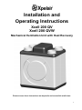
Installation and Operating Instructions Xcell 200 QV Xcell 200 QVW Mechanical Ventilation Unit with Heat Recovery Please ensure these instructions are kept safe and accessible at all times. 1 Table of Contents 1 2 3 4 General Information .................................................................................................................... 3 Components and Materials of Construction ............................................................................. 3 Regulations and Safety Instructions ......................................................................................... 3 Application and Planning ........................................................................................................... 4 4.1 4.2 4.3 5 Application .................................................................................................................................................4 MVHR operation overview.........................................................................................................................4 MVHR installation planning .......................................................................................................................4 Installation ................................................................................................................................... 5 5.1 General information ...................................................................................................................................5 5.2 Impact noise reduction ..............................................................................................................................5 5.3 Wall mounting the MVHR ..........................................................................................................................5 5.4 Heat exchanger retaining bracket .............................................................................................................5 5.5 Ducting ......................................................................................................................................................6 5.5.1 Duct connections................................................................................................................................6 5.5.2 Left-handed installation duct connections (viewed from the top of the MVHR) .................................7 5.6 Condensate drain ......................................................................................................................................7 5.7 Typical installation example ......................................................................................................................7 5.8 Installation dimensions ..............................................................................................................................8 5.8.1 MVHR unit ..........................................................................................................................................8 5.8.2 Wall brackets......................................................................................................................................9 6 Technical Data........................................................................................................................... 10 6.1 Air flow settings (Xcell 200 QV model only) ........................................................................................... 10 6.2 Air flow settings (Xcell 200 QVW model only) ........................................................................................ 10 6.2.1 PCB Port pins (Xcell 200 QVW model only): .................................................................................. 10 6.3 Factory speed settings: .......................................................................................................................... 10 6.4 Technical data: ....................................................................................................................................... 11 6.5 Applied Energy accessories for manual or automatic MVHR operation: ............................................... 11 6.6 Applied Energy MVHR spares: .............................................................................................................. 11 7 Electrical Wiring Diagrams ....................................................................................................... 12 7.1 7.2 7.3 7.4 7.5 8 Controller Functions ................................................................................................................. 17 8.1 8.2 8.3 8.4 8.5 8.6 8.7 9 Manual 2-speed switch (Xcell 200 QV only) .......................................................................................... 12 Automatic 3-speed switch (Xcell 200 QVW only) ................................................................................... 13 Automatic 3-speed switch & CO2 sensor (Xcell 200 QVW only) ............................................................ 14 Automatic 3-speed switch, CO2 sensor & up to three humidity sensors (Xcell 200 QVW only) ............ 15 Automatic 3-speed switch & up to four humidity sensors (Xcell 200 QVW only) ................................... 16 Manual 2-speed switch (Xcell 200 QV model only) ............................................................................... 17 Automatic 3-speed switch (Xcell 200 QVW model only) ........................................................................ 17 CO2 sensor (Xcell 200 QVW model only) .............................................................................................. 18 Humidity sensor (Xcell 200 QVW model only) ....................................................................................... 18 Automatic defrost protection (Xcell 200 QVW model only) .................................................................... 18 Fan fault monitoring (Xcell 200 QVW model only) ................................................................................. 19 Defrost heater unit .................................................................................................................................. 19 Maintenance .............................................................................................................................. 20 9.1 Filters ...................................................................................................................................................... 20 9.1.1 Removing and re-fitting the filters ................................................................................................... 20 9.2 Air filter box (optional accessory) ........................................................................................................... 20 9.3 Cleaning the heat exchanger ................................................................................................................. 21 10 Malfunctions .............................................................................................................................. 21 10.1 10.2 Fault locating table ................................................................................................................................. 21 Installation of replacement fans ............................................................................................................. 22 11 Customer Notes (to record details of filter / recuperator cleaning etc.) ................................ 24 Maintenance Log ............................................................................................................................. 26 GUARANTEE.................................................................................................................................... 28 2 1 General Information Read all these instructions & warnings fully before commencing installation. These installation and operating instructions must be observed during installation, operation, service and maintenance. This MVHR should only be installed and repaired by a qualified service technician. Improper repairs may expose the user to considerable danger. Under current regulations, the installation and operating instructions must be accessible at all times and must be handed to the technician for reference whenever work is being done on the MVHR. When moving out of the premises this MVHR has been installed in, please pass the instructions on to the next tenant / owner. Unpack the MVHR carefully and check for any visible signs of damage. If any damage is found contact the supplier. Only use original spares in order to avoid secondary damage. Please ensure that all packaging materials are disposed of properly in accordance with current environmental requirements. 2 Components and Materials of Construction The MVHR comprises of the following main components: Outer panels: PE plastic, white PS plastic, black Filters: G4 Filters fitted as standard. An external Air Filter Box with F5 or F7 Filters is also available as a separate accessory. Ducting spigots, Ø 125mm: PP plastic, light grey Heat exchanger: The Heat Exchanger is made from fully recyclable PS plastic. The Heat Exchanger integrated into the MVHR is based on the counter flow principle with triangular air ducts for supply and exhaust air. Internal air paths / casing: EPP, black Fans: Energy-saving EC DC Fans with optimal efficiency. Maintenance access cover: PS plastic 3 Regulations and Safety Instructions The Xcell 200 MVHRs are tested in accordance with the low-voltage directive 2006/95/EC and EMC directive 2004/108/EC. This appliance is not intended for use by persons (including children and the infirm) with reduced physical, sensory or mental capabilities, or lack of experience and knowledge, unless they have been given supervision or instruction concerning use of the appliance by a person responsible for their safety. Ensure that all relevant safety precautions (correct eye protection and protective clothing etc) are taken when installing, operating and maintaining this MVHR. Observe the safety regulations and warnings contained in this manual at all times. Failure to do so may result in damage to the unit or personal injury. This MVHR is intended for connection to fixed wiring. A means for disconnection must be incorporated in the fixed wiring. Installations and wiring must conform to current IEE Regulations (UK), local or appropriate regulations (other countries). All installations must be supervised by a qualified electrician. It is the installer’s responsibility to ensure that the appropriate building codes of practice are adhered to. This MVHR must not be installed near to sources of direct heat such as cookers/grills or where ambient temperatures may exceed 50ºC. When the MVHR is installed in a room containing a fuel burning appliance, precautions must be taken to avoid the backflow of gases into the room from the open flue of the fuel burning appliance. The instructions on periodic cleaning and/or changing of the Filters, the air inlet/outlet valves and the air inlet/outlet grilles must be strictly observed. The unit may only be connected to a 220-240V AC power supply. The following applications / installations are prohibited: The use of excessive fat-contaminated exhaust air, extracting explosive gases, extracting particle-contaminated air, extracting adhesive particulate matter. Installing the MVHR outdoors Connecting extractor hoods in the ventilation system Servicing of the MVHR may only be carried out by a qualified service technician. Contact details for authorised servicing by Xpelair approved technicians can be found on the back of this booklet. 3 4 Application and Planning 4.1 Application This MVHR is intended for installation in ventilation systems in houses, residential buildings and light commercial applications e.g. offices and meeting rooms etc. Upon completion of the system, there should be no safety, health or environmental risks present. The manufacturer of the MVHR assumes no liability for this. Part L – Buildings other than dwellings: Approved Document L2A: Conservation of fuel and power (New buildings other than dwellings) Approved Document L2B: Conservation of fuel and power (Existing buildings other than dwellings) 4.2 MVHR operation overview Using two Fans, each above a filter in separate ducts, the MVHR draws in external air from the outside and exhaust air from odourcontaminated and moisture-laden rooms (kitchen, bathroom, WC) in the house. Both of these air flows are passed through a cross counter flow Heat Exchanger whereby the exhaust air releases heat and the external air absorbs heat. The air ducts are separated from one another to prevent odour pollution between external and exhaust air. Using suitable air ducts and adjustable air inlet valves (separate accessories), the heated external air is blown into the house and the cooled exhaust air is ducted out of the building. There are numerous accessories available for manually or automatically controlling the MVHR, see section 6.6. 4.3 MVHR installation planning MVHR system designs must comply with the current standards or the approved edition on the original planning consent. Approved documents for Building Regulation in England and Wales: Part B: Approved Document B (Fire Safety) - Volume 1: Dwelling houses. Approved Document B (Fire Safety) - Volume 2: Buildings other than dwelling houses. Part F: Approved Document F - Ventilation. Part L – Dwellings: Approved Document L1A: Conservation of fuel and power (New dwellings) Approved Document L1B: Conservation of fuel and power (Existing dwellings) 4 Scottish Building Standards approved technical handbooks: Domestic Handbook: Section 2 – Fire Section 3 – Environment Section 6 – Energy Non-domestic Handbook: Section 2 – Fire Section 3 – Environment Section 6 – Energy 5 Installation 5.1 General information The MVHR should be aligned horizontally using a spirit level (for effective condensate drainage). The mains voltage must be 220-240V / 50-60 Hz. 5.2 Impact noise reduction With installation on wooden floors or other vibration-prone components, there may be combined impact noise (use rubber mounting feet). 5.3 Wall mounting the MVHR If mounting on low density walls i.e. plaster boarded stud walls use the following fixing method: Use 15 mm nominal plywood backing board to connect directly to the wall internal frame stud and then mount the MVHR unit on the plywood. Ensure internal thermal or sound insulation is installed inside the stud wall to prevent reverberation. The MVHR must be installed in a frost-free room preferably within the thermal envelope in order to keep heat losses via the MVHR surfaces and ventilation ducting to a minimum. Cellars, store rooms and insulated attics are suitable for this purpose. The MVHR may only be installed in dry, nonexplosion-proof rooms (protection category IP 20). The ambient temperature must not exceed +50°C. This MVHR must not be fitted in rooms or areas of the house with strong odours, which could then permeate into the MVHR and contaminate the fresh air supplied from the MVHR. The following criteria must also be met: Access is required for maintenance work (e.g. changing the filter) The condensate drain must be connected to a closed water trap and must have a sufficient gap. Approx. 50cm is ideal. If the condensate drain is located in a frost-prone area, then heat tracing must be provided. For wall-mounting the MVHR, three mounting brackets are supplied. wall- Mark out the fixing holes for the wallmounting brackets using the diagram shown in section 5.8.2 and drill the holes to suit the fixing screws to be used. Precisely align the three wall-mounting brackets on the wall using a spirit level and fix the three wall-mounting brackets to the wall with suitable fixing screws. Remove two screws from the top of the MVHR which align with the holes in the top wall-mounted bracket. Remove the four screws from the bottom of the MVHR which align with the slots in the two bottom wallmounted brackets. Place the MVHR on the three wall-mounted brackets and fix in place by re-fitting the six screws previously removed. 5.4 Heat exchanger retaining bracket Once the MVHR has been mounted in the right or left-handed orientation, the Heat Exchanger Retaining Bracket supplied (see picture below) must be fitted to the front of the MVHR as follows: Remove the Access Cover on the front of the MVHR by turning it to the left. Fit the Retaining Bracket and retaining screw supplied with the MVHR. Replace the Access Cover by turning it to the right. Important: The Heat Exchanger must only be removed for cleaning. Before removing the Heat Exchanger disconnect the MVHR from the mains supply. 5 5.5.1 Duct connections 5.5 Ducting Dwelling Extract Flexible ducting should only be used for final connections with special care taken to avoid restrictions and other conditions which will restrict air flow. Atmosphere Intake Dwelling Supply Atmosphere Discharge When installing ducting, care should be taken to ensure it is properly supported and secure with joints properly sealed. All ducting located in loft spaces and roof voids etc., which are unheated, must be insulated, together with the duct runs from the unit to atmosphere. All ducting fitted to the spigots on the MVHR should be secured in place with jubilee clips or a suitably sized plastic cable tie. Dia. 125mm duct spigots Right-handed installation duct connections For ease of installation the duct connections are located on top of the MVHR. - When viewed from the front of the MVHR in a right handed installation, the two duct connections on the left hand side are for: Drawing in fresh air from the outside (Atmosphere Intake) Extracting used air from the building (Dwelling Extract) - When viewed from the front of the MVHR in a right handed installation, the two duct connections on the right hand side are for: Extracting the used air out to atmosphere (Atmosphere Discharge) Supplying the heated fresh air into the building (Dwelling Supply) - The Xcell 200 MVHR can be installed right or left-handed without any additional modification, i.e. the mounting brackets supplied with the MVHR can be fitted to the front or the rear, and therefore the duct connections can be determined on-site. See the 5.5.2 for the left hand duct connections. - 6 5.5.2 Left-handed installation duct connections (viewed from the top of the MVHR) Atmosphere Discharge Atmosphere Intake Atmosphere Intake Dwelling Extract Dwelling Supply 5.6 Condensate drain A condensate drain must be fitted to run to the building waste water system in accordance with the Building Regulation H1. The Condensate Drain Tube is connected to the MVHR through the hole on the underside of the plastic base. The Condensate Drain Tube can be adapted to the installation requirements. It is important that the Condensate Drain Tube is positioned higher than the water surface of the water trap and that the Condensate Drain Tube ends within the water head of the water trap. The Condensate Drain Tube should be checked annually and cleaned if necessary. A Condensate Drain Tube (Ø 20mm and 1.0m long) is supplied with each MVHR. The water trap must be purchased separately from a local plumbing stockist. 5.7 Typical installation example Exhaust air from the rooms (kitchen/bathroom/toilet) Supply air into the building (living rooms/bedrooms/children’s rooms) External air (fresh air) with vapour diffusion-resistant insulation Outgoing air from inside to outside with vapour diffusion-resistant insulation 7 5.8 5.8.1 8 Installation dimensions MVHR unit 5.8.2 Wall brackets 9 6 Technical Data 6.1 Air flow settings (Xcell 200 QV model only) Air flow rates can be changed by a qualified service technician using the adjustment potentiometers inside the Manual 2-Speed Switch purchased for this MVHR, as shown in the picture below. Two supply / exhaust air speed adjustment potentiometers The potentiometers adjust both Fan speeds simultaneously i.e. independent Fan speed control is not available. Turning the potentiometer to the right increases the control voltage / speed of both Fans and turning it to the left reduces the control voltage / speed of both Fans. There are two potentiometers, see section 6.3 below for the factory default speed settings. 6.2 Air flow settings (Xcell 200 QVW model only) Air flow rates can be changed by a qualified service technician using the adjustment potentiometers (3x blue) for the supply air Fan and (3x red) for the exhaust air Fan, as shown on the picture below. 3 pot’s for supply air speed adjustment PCB port pins 3 pot’s for exhaust air speed adjustment The potentiometers adjust the Fan speeds independently i.e. common Fan speed control is not available. Depending on the Fan speed selected (1, 2 or 3) the Fans have a specific control voltage of between 1.7 V minimum up to a maximum of 10.0 V. The control voltage for the supply air and exhaust air Fans is also adjusted via each set of three potentiometers on the PCB. S1 – Supply air speed 1 - blue potentiometer S2 – Supply air speed 2 - blue potentiometer S3 – Supply air speed 3 - blue potentiometer and and and S1 – Exhaust air speed 1 - red potentiometer S2 – Exhaust air speed 2 - red potentiometer S3 – Exhaust air speed 3 - red potentiometer Turning the potentiometer to the right increases the control voltage / speed of each Fan and turning it to the left reduces the control voltage / speed of each Fan. 6.2.1 PCB Port pins (Xcell 200 QVW model only): Via port pins on the PCB, the control voltage for each speed setting can be measured. The control voltage for the exhaust air and supply air Fans can be set separately at between 1.7 V and 10.0 V as described above. See also the wiring diagrams in section 7. 6.3 Factory speed settings: Speed 1: 70 m³/h - Low speed – preferably at night or during periods of absence Speed 2: 140 m³/h - Normal daytime operation Speed 3: 200 m³/h - Boost setting for increased air exchange Note: When the MVHR is being used with a Manual 2-Speed Switch, only speeds 2 and 3 will apply. 10 6.4 Technical data: Technical data Voltage / Frequency Max. current consumption Power consumption - Speeds 1, 2, 3 Air flow rate - Speeds 1, 2, 3 Air flow rate at 90 Pa Static Pressure Protection category Max. ambient temperature Dimensions (without ducting) - W x H x D Weight of MVHR Duct connections Condensate drain tube connections Filter class Efficiency of Heat Exchanger Sound pressure level (measured at a distance of 1m) - Speeds 1, 2, 3 Sound pressure level (measured at a distance of 3m) - Speeds 1, 2, 3 6.5 V / Hz A W m³/h m³/h IP °C mm Kg mm mm % dB (A) Specification ~ 220-240V / 50-60 Hz 0.80 20 / 42 / 106 70 / 140 / 200 220 20 50 600 x 595 x 425 17.5 125 20 G4 Up to 90% 30.0 / 34.0 / 45.0 20.5 / 24.5 / 34.5 Applied Energy accessories for manual or automatic MVHR operation: Part Description Notes Number Manual 2-Speed Switch 23513AW Automatic 3-Speed Switch 96005AA CO2 Sensor 96003AA Humidity Sensor 96009AA Air Filter Box 45014AA Class F5 Filter 95045AA Class F7 Filter 95047AA Defrost Heater Unit 44001AA 6.6 Units Suitable for the Xcell 200 QV MVHR only. Only one Manual 2-Speed Switch can be used per MVHR. Can be flush or surface mounted. Suitable for the Xcell 200 QVW MVHR only. Up to ten Automatic 3-Speed Switches can be used per MVHR. Can be flush or surface mounted. Suitable for the Xcell 200 QVW MVHR only. Only one CO2 Sensor can be used per MVHR unit. Can be surface mounted only. Suitable for the Xcell 200 QVW MVHR only. Can be surface mounted only. When used in conjunction with an Automatic 3-Speed Switch a maximum of four Humidity Sensors can be connected. When used in conjunction with an Automatic 3-Speed Switch and a CO2 Sensor a maximum of three Humidity Sensors can be connected. Suitable for all Xcell 200 MVHRs. Only one Air Filter Box is required per MVHR. Not supplied with Filters fitted, see below. Suitable for all Xcell 200 MVHRs. F5 Filter used in the air filter box only. Suitable for all Xcell 200 MVHRs. F7 Filter used in the air filter box only. Suitable for the Xcell 200 QVW MVHR only. Only one Defrost Heater Unit is required per MVHR. Applied Energy MVHR spares: Description Part Number Terminal Cover Heat Exchanger Motor (Outgoing Air) Motor (Supply Air) G4 Filters (pack of 2) Control PCB (Xcell 200 QVW only) 20mm Cable Clamp 12mm Cable Clamp 44301SK 44302SK 44312SK 44312SK 44305SK 44306SK 44307SK 44308SK 11 7 Electrical Wiring Diagrams E Green / Yellow (G/Y) Blue (Bl) Brown (Bn) L N Fuse (Bn) (Bl) (G/Y) N L 10V O/P 0V Unit Connection Terminals 10V O/P 0V MS2 Controller (23513AW). Xcell 150 QV controlled by a 2-Speed (MS2) Controller. 1 Phase (220-240Vac) (50/60Hz) N ~ L Fused Switch Spur (By Others). Xcell 150 QV Internal Terminals 12 Manual 2-speed switch (Xcell 200 QV only) 7.1 T T T Transformer Q3SP Controller (96005AA). T T AEP Ref: Xcell 150-04e-a T Automatic 3-speed switch (Xcell 200 QVW only) 7.2 L N Fused Switch Spur (By Others). Fuse Fused Switch Spur (By Others). Jumper position: Jp1 = open Jp2 = closed Jp3 = open Jp4 = closed Jp5 = open Jp6 = closed Jp7 = open Jp8 = closed Jp9 = open Jp10 = open (G/Y) Green / Yellow Blue E (Bl) N ~ (Bn) L Brown 1 Phase (220-240 Vac) (50/60Hz) 13 T T T T Q3SP Controller (96005AA) Transformer QCO Controller (96003AA) T T AEP Ref: Xcell 150-03e/a L N Fused Switch Spur (By Others). Fuse Jumper position: Jp1 = open Jp2 = closed Jp3 = open Jp4 = closed Jp5 = open Jp6 = closed Jp7 = open Jp8 = closed Jp9 = open Jp10 = closed (G/Y) Green / Yellow Blue E (Bl) N ~ (Bn) L Brown 1 Phase (220-240 Vac) (50/60Hz) 14 Automatic 3-speed switch & CO2 sensor (Xcell 200 QVW only) 7.3 T T T Transformer Q3SP Controller (96005AA). T T QHS Controller (96009AA). QCO Controller (96003AA). QHS Controller (96009AA). QHS Controller (96009AA). AEP Ref: Xcell 150-05e-a T Automatic 3-speed switch, CO2 sensor & up to three humidity sensors (Xcell 200 QVW only) 7.4 L N Fused Switch Spur (By Others). Fuse Fused Switch Spur (By Others). (G/Y) Green / Yellow Blue E (Bl) N ~ (Bn) L Brown Jumper position: Jp1 = open Jp2 = closed Jp3 = open Jp4 = closed Jp5 = open Jp6 = closed Jp7 = open Jp8 = closed Jp9 = open Jp10 = closed 1 Phase (220-240 Vac) (50/60Hz) 15 T T T Transformer T T QHS Controller (96009AA). QHS Controller (96009AA). QHS Controller (96009AA). QHS Controller (96009AA). Q3SP Controller (96005AA). T AEP Ref: Xcell 150-06e-a L N Fused Switch Spur (By Others). Fuse Fused Switch Spur (By Others). (G/Y) Green / Yellow Blue E (Bl) N ~ (Bn) L Brown Jumper position: Jp1 = open Jp2 = closed Jp3 = open Jp4 = closed Jp5 = open Jp6 = closed Jp7 = open Jp8 = closed Jp9 = open Jp10 = closed 1 Phase (220-240 Vac) (50/60Hz) 16 Automatic 3-speed switch & up to four humidity sensors (Xcell 200 QVW only) 7.5 8 Controller Functions 8.1 Manual 2-speed switch (Xcell 200 QV model only) The terminal box for all wiring connections is situated on top of the MVHR. Refer to section 7.1 for the relevant wiring diagram. Only one Manual 2-Speed Switch may be connected to each MVHR. Minimum size of 3-core cable to be used: Power supply – 1.5mm² Switch – 0.5mm² Note – use a spanner to tighten all cable glands This switch option is for manual control only and therefore none of the Xpelair automatic control accessories listed below are compatible with this switch. Speed settings: Speed 1: Normal operation Speed 2: Boost setting for increased air exchange o Refer to Section 6 for details on default speed settings / adjustment. 8.2 Automatic 3-speed switch (Xcell 200 QVW model only) The terminal box for all wiring connections is situated on top of the MVHR. Refer to sections 7.2, 7.3, 7.4 and 7.5 for the relevant wiring diagrams and additional controllers that are compatible with the Automatic 3-Speed Switch. With jumper 8 selected on the PCB, the Automatic 3-Speed Switch is active. Up to ten Automatic 3Speed Switches can be connected in parallel to each MVHR. Minimum size of 3-core cable to be used: Power supply – 1.5mm² Switch – 0.5mm² Note – use a spanner to tighten all cable glands Key features: Plus and minus keys to manually change speed 3 LEDs for speed indication / white housing Indicators: - Moisture Protection LED 1 flashes briefly every second Important: an interval time is programmed into the Moisture Protection setting. Interval time: 17 mins. ON 13 mins. OFF, etc. Speed 1 LED 1 on Speed 2 LED 2 on Speed 3 LED 3 on MVHR OFF* LEDs 1+2+3 off Filter service LED 1 flashes quickly continuously (until reset as described below) Timer reset LEDs 1+2+3 flash 5 times in quick succession (to acknowledge reset is complete) Fault alarm LEDs 1+2+3 flash every second Fault alarm reset Mains voltage briefly interrupted Settings: MVHR On* Press plus key MVHR Off* Press minus key until speed 0 is reached, i.e. 3>2>1>Moisture Protection>0, MVHR OFF Reset timer Press plus and minus keys together and hold for 2 seconds Speed 3 Speed 3 time-limited (only when no other controllers are used alongside the Automatic 3-Speed Switch): after 1 hour, the MVHR automatically switches back to Fan speed 2. On/off function (only possible when no other controllers are used alongside the Automatic 3-Speed Switch) can be disabled with jumper 9 on the PCB. This means the speed switches from Ventilation to Moisture Protection – the lowest Fan speed. Filter service indicator: The period for the filter service timer (3 months) is set and stored and cannot be changed. Once the period of 3 months has expired, the Automatic 3-Speed Switch will indicate that a filter service is necessary whereby the LED for Fan speed 1 flashes every second. Once the filter has been successfully serviced i.e. cleaned or changed, the filter service timer on the Automatic 3-Speed Switch can be reset by pressing both OPERATING KEYS (and holding for 2 seconds) and the filter service indicator on the switch will go out. Resetting is acknowledged by LED 1 flashing quickly 5 times. In the event of a full MVHR service outside the above 3 month period, the timer can also be reset, without the filter service timer having completed its runtime, by pressing both operating keys together and holding for 10 seconds. Resetting is acknowledged by LED 1 flashing quickly 5 times. 17 8.3 CO2 sensor (Xcell 200 QVW model only) The terminal box for all wiring connections is situated on top of the MVHR. The CO2 Sensor will only function in conjunction with the Automatic 3-Speed Switch, described in section 8.2. Refer to sections 7.3 and 7.4 for the relevant wiring diagrams and associated controllers that are compatible with the CO 2 Sensor. With jumper 10 selected on the PCB, the CO2 Sensor is active. Only one CO2 Sensor may be connected to each MVHR. Minimum size of 3-core cable to be used: Power supply – 1.5mm² Switch – 0.5mm² Note – use a spanner to tighten all cable glands The MVHR only reacts to the CO2 sensor when Fan speed 2 is activated on the Automatic 3-Speed Switch. Fan speed 2 is always displayed on the Automatic 3-Speed Switch, regardless of whether the CO2 values are displayed as <900 ppm (speed 1) or >1100 ppm (speed 3) on the CO2 Sensor. With this setting, the CO2 Sensor is always prioritised. As soon as the Moisture Protection speed, speed 1 or speed 3 is manually activated on the Automatic 3-Speed Switch, the CO2 Sensor is deactivated. Switch points of the CO2 sensor: > 1.5 V MVHR switches from speed 2 to speed 1; > 5.0 V MVHR switches from speed 1 to speed 2; > 7.5 V MVHR switches from speed 2 to speed 3; < 5.0 V MVHR switches from speed 3 to speed 2; 8.4 < 900 ppm > 1000 ppm > 1100 ppm < 1000 ppm Humidity sensor (Xcell 200 QVW model only) The terminal box for all wiring connections is situated on top of the MVHR. Refer to sections 7.4 & 7.5 for the relevant wiring diagrams. Minimum size of 3-core cable to be used: Power supply – 1.5mm² Switch – 0.5mm² Note – use a spanner to tighten all cable glands This product is designed to measure humidity and temperature in indoor applications. It uses a capacitive sensor element for the humidity measurement. Factory default setting is 40% RH, no adjustment is possible. Note: When using Humidity Sensors in conjunction with the Automatic 3-Speed Switch a maximum of four Humidity Sensors can be connected. When using Humidity Sensors in conjunction with the Automatic 3-Speed Switch and a CO2 Sensor a maximum of three Humidity Sensors can be connected. 8.5 Automatic defrost protection (Xcell 200 QVW model only) In order to prevent the Heat Exchanger from freezing when the outside temperature is low, a frost protection monitor has been integrated (Xcell 200 QVW models only). Two temperature ranges can be set via the PCB jumpers 4 and 5 (see table below). Option 1 (Factory default setting): If the temperature in the outgoing air duct falls below 4°C the supply air Fan will stop (the exhaust air Fan will remain on). When the outgoing air temperature reaches 7°C again the supply air Fan comes back on automatically. Option 2: If the temperature in the outgoing air duct falls below 6°C the supply air Fan will stop (the exhaust air Fan will remain on). When the outgoing air temperature reaches 9°C again the supply air Fan comes back on automatically. Settings table: Option 1 2 18 Temperature (outgoing air) + 4°C + 6°C Temperature (outgoing air) + 7°C + 9°C Jumper 4 Jumper 5 1 1 0 1 8.6 Fan fault monitoring (Xcell 200 QVW model only) Should the supply air Fan fail the exhaust air Fan will switch off automatically. Fault indication: On the Automatic 3-Speed Switch, all 3 LEDs will flash. Should the exhaust air Fan fail the supply air Fan does not switch off. Fault indication: On the Automatic 3-Speed Switch, all 3 LEDs will flash. Using the ^ key, the supply air Fan speed can be switched down in stages until OFF is reached, whereby the fault indicator will also go out. Resetting is executed by briefly switching off the mains voltage. 8.7 Defrost heater unit When the incoming air temperature drops below the set temperature (0°C to 3°C), the Defrost Heater Unit will switch on and warm the incoming air prior to it arriving at the MVHR to prevent ice forming within the MVHR Heat Exchanger. When the incoming air temperature rises above the set temperature (0°C to 3°C), the defrost heater unit will switch off. Note: The fly screen must be cleaned regularly. 19 9 Maintenance 9.1 Filters The MVHR should never be operated without Filters. However, depending on the actual volume of contaminants in the environment, the MVHR Filters need to be checked and cleaned at least twice a year and replaced at least on an annual basis. The original external / exhaust air Filters contain G4 Filter fibre enclosed in a cardboard frame. Replacement G4 Filters are of a frameless construction. Contact details for purchasing new Filters or servicing by Xpelair approved technicians can be found on the back of this booklet. 9.1.1 Removing and re-fitting the filters 1. 2. 3. 4. Disconnect the MVHR from the mains supply. Remove the Access Hatch by turning it to the left. Remove the two Filters from the MVHR (external air and exhaust air - see picture below). Insert cleaned or new Filters into their correct positions in the MVHR. a. Please note the ‘clean side’ of the filter is placed next to the Heat Exchanger. b. Filters can be cleaned by gently knocking together to remove dust / dirt. 5. Replace the Access Hatch by locating and turning to the right. 6. Switch the mains supply back on. 7. The MVHR is ready to recommence operation. 9.2 Air filter box (optional accessory) The MVHR is fitted with G4 Filters as standard. To protect allergy sufferers against environmental pollution, for example, it may be useful to install a filter box with finer Filters. These Filters are designed to offer the longest service life and lowest pressure loss and are installed in a box immediately after the supply air outlet. Class F5 or F7 Panel Filters are available as the filter elements. The F5 or F7 Panel Filters fitted in the Air Filter Box should be checked for cleaning / replacement at the same time as the other MVHR Filters. Please contact the UK sales office for further details, contact details can be found on the back of this booklet. Please note: If the external air is drawn in via a geothermal Heat Exchanger, a class G4 Filter should be installed in the intake tower. 20 9.3 Cleaning the heat exchanger The Heat Exchanger should be cleaned by a specialist technician as and when required depending on the level of contamination, but at least every 2 years. Contact details for servicing by Xpelair approved technicians can be found on the back of this booklet. The cleaning procedure is as follows: 1. 2. 3. 4. 5. 6. 7. 8. 9. 10. 11. Disconnect the MVHR from the mains supply. Remove the Access Hatch by turning it to the left. Remove the Retaining Bracket located in front of the Heat Exchanger by removing the screw. Carefully pull the Heat Exchanger out forwards using the black plastic strap around the Heat Exchanger, keeping it horizontal to avoid damaging the EPP housing. Thoroughly rinse the Heat Exchanger with lukewarm water and allow all the water to drain off. Residual moisture will evaporate when the MVHR is operated. Carefully insert the cleaned Heat Exchanger, keeping it horizontal to avoid damaging the EPP housing. Replace the Heat Exchanger Retaining Bracket and retaining screw. Replace the Access Hatch by locating and turning to the right. Switch the mains supply back on. The MVHR is ready to recommence operation. 10 Malfunctions Important: Servicing of the MVHR may only be carried out by a qualified service technician. Contact details for servicing by Xpelair approved technicians can be found on the back of this booklet. 10.1 Fault locating table FAULT / MALFUNCTION CHECK The mains supply is on. Supply air or exhaust air Fan does not work All 3 LEDs on the Automatic 3Speed Switch are flashing. (Xcell 200 QVW models only). The mains supply is on. Supply air or exhaust air Fan does not work Supply air and/or exhaust air flow rate is too low No water coming through Condensate Drain Tube Noise coming from the MVHR No LEDs on the Automatic 3Speed Switch are flashing. (Xcell 200 QVW models only). LED on the Automatic 3-Speed Switch is flashing - filter service indicated. (Xcell 200 QVW models only). Drops of water on the underside of the MVHR. Fans are noisy. POSSIBLE CAUSE All Xcell 200 models: Supply air Fan defective Exhaust air Fan defective Fan blade catching on inner EPP housing Contact fault on Fan control or power leads Xcell 200 QV model only: The Manual 2-Speed Switch PCB is defective Xcell 200 QVW model only: Control PCB defective Mains supply interrupted Contact fault on Fan control or power leads Fuse has blown: Mains supply fuse or Supply cord plug fuse - Filter service period has expired - No water in siphon Condensate water drain blocked - Increased air resistance due to contaminated Filters and/or Heat Exchanger Obstruction in the duct system Room air regulator valves not open wide enough Fan blade touching inner EPP housing - Note - This table may be subject to technical amendments. 21 10.2 Installation of replacement fans Should either Fan develop a fault and need to be replaced, contact details for servicing by Xpelair approved technicians can be found on the back of this booklet. The replacement procedure is as follows: 1. 2. 3. 4. 5. 6. 7. Disconnect the MVHR from the mains supply. Remove the Access Hatch by turning it to the left. Remove the two G4 Filters. Remove the Heat Exchanger Retaining Bracket and retaining screw. Remove the Heat Exchanger carefully, keeping it horizontal to avoid damaging the EPP housing. Remove the four Terminal Cover retaining screws. Remove the Terminal Cover. 8. The following procedure applies to both MVHR Fans, only remove faulty Fans from the MVHR: a) Identify the faulty Fan within the MVHR. Note: The upper Fan (A) provides the supply air and the lower Fan (B) provides the exhaust air. b) Disconnect the power and control leads of the faulty Fan from the PCB (Xcell 200 QVW model only) or Terminal Block (Xcell 200 QV model only), whichever applies. Refer to Section 7 for the relevant wiring diagram to correctly identify which leads to disconnect for each Fan. c) Firmly attach string to the two leads of the faulty Fan. Note: The string, at least 3 metres long, must be secured tightly but not in a way that will become jammed when pulled through the cable channels inside the unit i.e. no large tied knots. 22 d) Remove the Bell Mouth covering the faulty Fan. Note: Insert a flat bladed screwdriver into the recess on the edge of the Bell Mouth & lever it out carefully to avoid damaging the EPP housing. e) Remove the three retaining screws of the faulty Fan. f) Push the leads of the faulty Fan down into the top of the MVHR by around 30mm. 9. 10. 11. 12. 13. 14. 15. 16. g) Remove the faulty Fan (attached to the plastic Motor Mount) also pulling through the faulty Fan leads and attached string. h) Remove the four retaining screws to remove the plastic Motor Mount from the faulty Fan, note the orientation of the faulty Fan and it’s leads in relation to the slots in the plastic Motor Mount. i) Assemble the plastic Motor Mount to the new Fan & secure with the four retaining screws. j) Untie the string from the faulty Fan leads and attach to the new Fan leads. k) Position new Fan in the MVHR, pulling through the string & Fan leads to take up the slack as it‘s moved into place. Ensuring that the plastic Motor Mount is correctly orientated and is flat against the EPP housing. l) Secure the new Fan into place with the three retaining screws. m) Remove the string from the new Fan leads. n) Connect the power and control leads of the new Fan to the PCB / Terminal Block (whichever applies). Refer to Section 7 for the relevant wiring diagram to correctly identify where to reconnect the power / control leads. o) Replace the Bell Mouth, push gently into the EPP housing but ensure it is clips into place. p) Spin the blades of the new Fan to ensure that it moves freely and is not obstructed in any way. If any obstruction is present the Fan has not been positioned correctly within the EPP housing. Dismantle again to correctly fit ensuring that the plastic Motor Mount is correctly orientated and is flat against the EPP housing. Repeat step 8 for the other Fan should both Fans need replacing. It is recommended that only one Fan is replaced at a time. Replace the Terminal Cover and secure with the four fixing screws. Note: Ensure no leads or cables are trapped underneath the Terminal Cover before securing. Replace the Heat Exchanger carefully, keeping it horizontal to avoid damaging the EPP housing. Replace the Heat Exchanger Retaining Bracket & retaining screw. Replace the two G4 Filters. Replace the Access Hatch by locating and turning to the right. Switch the mains supply back on. The MVHR is ready to recommence operation. 23 11 Customer Notes (to record details of filter / recuperator cleaning etc.) 24 Customer Notes (continued) 25 Maintenance Log Date 26 Action Signature/ Stamp This Xpelair MVHR was purchased from: Supplier stamp On ________________________(date) 27 GUARANTEE Terms and Conditions for UK & ROI (outside UK & ROI contact your local distributor) We, Redring Xpelair Group Limited, guarantee this product against faulty workmanship and material defects for a period of 5 years from the date of purchase subject to regular servicing by Redring Xpelair Group Limited, or our approved agents. In the event of a product breakdown during the guarantee period, you should initially contact your installer, before contacting Redring Xpelair Group Limited on the Technical line number below providing that: a) The product has been installed in a residential or light commercial environment. b) The product has been correctly installed and commissioned in accordance with our instructions and is being used on the supply circuit or voltage printed on the rating plate. c) The product has been used in accordance with these instructions and has not been tampered with or otherwise subject to misuse, neglect or accident. d) The product has been regularly maintained in accordance with these instructions and the airway is unobstructed. e) The product has not been taken apart, modified or repaired except by a person authorised by us. f) Evidence of the date of purchase in the form of an invoice or receipt will be required in order to qualify under the terms of this guarantee. g) For the service work to be undertaken free of charge, the work must only be undertaken by Redring Xpelair Group Limited, or our approved agents. h) Service under guarantee has no effect on the expiry date. The guarantee on any exchanged parts or product ends when the original guarantee period ends. i) In the event of a product being returned to Redring Xpelair Group Limited and not found to be faulty, the product would be available for collection from the relevant premises within one month and if not collected it would be disposed of or delivered by Redring Xpelair Group Limited and a delivery charge made. EXCLUSIONS This guarantee does not apply to the repair or replacement of Filters, Accessories, Isolating switches, Electrical cable, Fuses and/or Circuit breakers or annual servicing. This guarentee covers products supplied by Redring Xpelair Group Limited only and does not cover other products and components used to create a system that have not been purchased from Redring Xpelair Group Limited. The responsibility for the suitability of the complete system for the specific application remains the responsibility of the original specification engineer. This guarantee does not cover damage or defects arising from poor or incorrect installation, improper use or lack of maintenance. It is the responsibilty of the installer to check that the installation parameters meet the requirements of the product, and any relevant regulations. If we are called out to a fault, which is subsequently identified as being an installation fault, we will make a charge. It is important that the routine checks are completed before calling us out, as many issues can be simply diagnosed and resolved. We make no guarantees as to response times for repairs. We will endeavour to achieve the most timely response possible but while we indicate an average response time, this should not be taken as a guarantee. The guarantee applies to a repair or replacement (at our discretion) of the product subject to the conditions above, and does not cover compensation for the loss of the product or consequential loss of any kind. This guarantee does not affect your statutory rights. Booklet 23842AA Rev. C Redring Xpelair Group Limited Newcombe Way, Peterborough PE2 6SE Customer Care / Technical Line: 0844 372 7766 Customer Care / Technical Fax: 0844 372 7767 Sales Line: 0844 372 7750 Sales Fax 0844 372 7760 www.redringxpelair.co.uk 28 Xpelair is a registered trademark of Redring Xpelair Group Limited. Redring Xpelair Group Limited reserve the right to alter product specifications or appearance without prior notice. All finishes and diagrams in this booklet are as accurate as printing processes allow.